MIT BP1 Automation Installation and operating instructions

MOVING iMAGE TECHNOLOGIES
INSTRUCTIONS
FOR
INSTALLATION, OPERATION, AND MAINTENANCE
OF
BP1 Automation
Part numbers A000392 / A000393
Manual Version 0.1
MOVING iMAGE TECHNOLOGIES, LLC.
17760 Newhope St.
Fountain Valley, CA
Telephone: (714) 751-7998
Fax: (714) 429-7717
www.movingimagetech.com
MiT

R000226 BP1 Automation 2 v.0.1 03/21
BP1 Automation Manual
TABLE OF CONTENTS
Section Page
1. SAFETY 3
2. GENERAL DESCRIPTION 3
3. INPUTS AND OUTPUTS DEFINED 5
4. UNPACKING 8
5. INSTALLATION & WIRING 9
6. CONFIGURING PROJECTOR IMB 12
APPENDICES: RETROFIT PROCEDURE, PARTS LISTS, & WARRANTY 23
The information in this document is subject to change without notice and does not
represent a commitment on the part of Moving Image Technologies (hereinafter referred
to as MIT). MIT does not assume responsibility for errors that may appear in this
document. MIT or its subsidiaries, designated representatives, and any vendor are not
responsible in any way for any liabilities or loss resulting from the use or misuse of this
document.
Copyright © 2021 by MIT
All Rights Reserved
All copyrights and trademarks are the property of their respective owners.
MOVING iMAGE TECHNOLOGIES, LLC.
Fountain Valley, CA
Telephone: (714) 751-7998
www.movingimagetech.com

R000226 BP1 Automation 3 v.0.1 03/21
1. SAFETY
1.1 Low Voltage device
The Moving iMage Technologies model BP1 Automation is a low voltage device, with
power provided by a UL-Recognized low voltage DC power supply. The BP1 has not been
evaluated or certified for connection of any parts of it to AC line voltages, and such
connection is not recommended.
2. GENERAL DESCRIPTION
The BP1 is an automation interface designed to accept commands from a Barco d-cinema
projector with the Alchemy IMB (Integrated Media Block). The BP1 buffers those signals
then outputs control signals to the various pieces of equipment in the cinema auditorium
such as dimmer and masking control.
The BP1 system is built on 19” wide, 1 RU steel chassis. The main circuit board
incorporates detection logic that may be configured to suit typical fire alarm panel output,
including dry contact, and AC and DC voltages of 12 or 24V. It includes LEDs on the front
panel to indicate the Power status, Fire Alarm status, and a switch to manually reset the
Fire Alarm condition after the alarm signal is no longer present.
A second board provides relays buffering masking controls for up to 10 Amperes current.
A terminal block provides the following connection points:
12VDC power in
Outputs to a dimmer: Mid, Down, and UP
Buffered outputs for Masking: Flat and Scope formats
Fire Alarm Panel Input

R000226 BP1 Automation 4 v.0.1 03/21
xxxxxxxxxxxxdddddd
F FF FZ Z F FF FZ Z
P PP PP P
P PP PP P
P PP PZ Z
P PP PZ Z
d d
d d
d d
d d
d d
d d
d d
d d
d d
d d
d d
d d
d d
d d
d d
d d
xxP
xxPxxP
xxP
1
8
FIRE ALARM
FIRE ALARM
C003326-001
DIM MID
DIM DOWN
DIM UP
DIM COM
MASK FLAT
MASK SCOPE
MASK COM
+12V
12V COM
PPA<AA
P
P
P
P
P
P
F
F
F
F
F
F
F
F
F
F
F
F
ZZZFFFFFF
PPPPPP
PPPPPP
Z ZF FF F
P PA AA A
PPAAAA
P PF FF F
P
P
PA
A
AA
A
A
P
P
PA
A
AA
A
A
PPAAAA
P
P
d
d
PP
d
d
P
PA
A
AA
A
AA
A
AA
A
A P
P
d
d
PP
d
d
P
PA
A
AA
A
AA
A
AA
A
A
úúúúxxxxxxxx
PPFFFF
úúúúxxxxxxxx úúúúxxxxxxxx
ZZZZZZPPPPPPPPPPPP
P
P
PA
A
AA
A
A
P PF FF F
P PF FF F
P PF FF F
P PF FF F
PPAAAA
PPPPPPPP
PPPPPPPP
AAAAAAAA
AAAAAAAA
AAAAAAAA
AAAAAAAA
PPFFFF
ZZZFFFFFF
P PF FF F
PPAAAA PPAAAA
P PF FF F
PPFFFF
P PF FF F
P PF FF F
P PF FF F
P PF FF F
PPFFFF
PPFFFF
PPFFFF
PPPPPPPP
PPPPPPPP
AAAAAAAA
AAAAAAAA
AAAAAAAA
AAAAAAAA
PPAAAA
PPAAAA PPAAAAPPAAAA
P
P
d
d
PP
d
d
P
PA
A
AA
A
AA
A
AA
A
AP
P
d
d
PP
d
d
P
PA
A
AA
A
AA
A
AA
A
AP
P
d
d
PP
d
d
P
PA
A
AA
A
AA
A
AA
A
A
PPAAAA
PPAAAA
P PF FF F
P PF FF FP PF FF F
P PF FF F
PPAAAA
ZZZZZZZZxxxxxxxxxxxxxxxx
PPFFFF
PPFFFF
PPFFFF
PPFFFF
PPPPPPPP
PPPPPPPP
AAAAAAAA
AAAAAAAA
AAAAAAAA
AAAAAAAA
PPPPPPPP
PPPPPPPP
AAAAAAAA
AAAAAAAA
AAAAAAAA
AAAAAAAA
P PF FF F
PPPPPPPPP
PPPPPPPPP
AAAAAAAAA
AAAAAAAAA
AAAAAAAAA
AAAAAAAAA
P PF FF F
PPFFFF
PPFFFF
PPFFFF
PPFFFF
PPAAAA PPAAAA
P PF FF F
P PF FF FP PF FF F
P PF FF F
P
P
PA
A
AA
A
AP
P
PA
A
AA
A
A
PPAAAAPPAAAA
PPPPPPPP
PPPPPPPP
AAAAAAAA
AAAAAAAA
AAAAAAAA
AAAAAAAA
PPPPPPPP
PPPPPPPP
AAAAAAAA
AAAAAAAA
AAAAAAAA
AAAAAAAA
PPAAAAPPAAAAPPAAAA
P
P
d
d
PP
d
d
P
PA
A
AA
A
AA
A
AA
A
AP
P
d
d
PP
d
d
P
PA
A
AA
A
AA
A
AA
A
AP
P
d
d
PP
d
d
P
PA
A
AA
A
AA
A
AA
A
A
ZZZZZZZZxxxxxxxxxxxxxxxx
PPPPPPPPAAAAAAAAAAAAAAAA
PPPPPPPP
PPPPPPPP
AAAAAAAA
AAAAAAAA
AAAAAAAA
AAAAAAAA
PPPPPPPPAAAAAAAAAAAAAAAA
PPPPPPPP
PPPPPPPP
AAAAAAAA
AAAAAAAA
AAAAAAAA
AAAAAAAA
PPPPPPPPAAAAAAAAAAAAAAAA PPPPPPPPAAAAAAAAAAAAAAAA
PPPPPPPPAAAAAAAAAAAAAAAA
PPPPPPPP
PPPPPPPP
AAAAAAAA
AAAAAAAA
AAAAAAAA
AAAAAAAA
PPAAAA PPAAAA
P
P
d
d
PP
d
d
P
PA
A
AA
A
AA
A
AA
A
AP
P
d
d
PP
d
d
P
PA
A
AA
A
AA
A
AA
A
A
xx xx
xx xxxx xxxx xxxx xx
P
P
d
d
PP
d
d
P
PA
A
AA
A
AA
A
AA
A
AP
P
d
d
PP
d
d
P
PA
A
AA
A
AA
A
AA
A
A
xxPxxP
xxP xxP
xxPxxP
´´ú
´´ú
FFZ
FFP FFP
úúúúúúúú
14
8
1
121110987612345
TB1
POWER
FIRE ALARM
RELEASE
ACTIVE
IMC-BP1 AUTOMATION
MiT
Figure 2-1: BP1 System Outline
The main circuit board is also available as a separate component which may be used to
retrofit previous MiT automation models utilizing the JNIOR device, such as the IMC-3J.
For additional information about using the BP1 board in a retrofit, please see Sec. 5.

R000226 BP1 Automation 5 v.0.1 03/21
3 INPUTS & OUTPUTS
The BP1 control board has been designed specifically to interface to a Barco Series 2
projector with an Alchemy ICMP-X IMB. The BP1 connectors are designated accordingly.
You may use a different method of controlling the unit, but custom cabling may be
required. Or you may assign different functionality to the connectors than the default
functions listed below, if desired.
All connections between the BP1 and projector use 8-pin, RJ-45 connectors. The cables
used may be modular type or Local Area Network cables, i.e. CAT 5, CAT6, etc, however
they are not used as network cables. Cables must be 1:1 straight-through, not a
crossover type.
In the table below, refer to the connectors as designated in Figure 3-1.
Figure 3-1: Control Board

R000226 BP1 Automation 6 v.0.1 03/21
Note: NC = Not Connected
Inputs
J2 ICMPX GPO5-8
J2-1 Screen Lights On
J2-2 Common
J2-3 Screen Lights Off
J2-4 Common
J2-5 NC
J2-6 NC
J2-7 NC
J2-8 NC
J3 ICMPX GPO1-4
J3-1 Dimmer Mid
J3-2 Common
J3-3 Dimmer Down
J3-4 Common
J3-5 Dimmer Up
J3-6 Common
J3-7 NC
J3-8 Common
J4 PROJ. GPO5-8
J4-1 Masking Flat
J4-2 Common
J4-3 Masking Scope
J4-4 Common
J4-5 XL Mover 2D
J4-6 Common
J4-7 XL Mover 3D
J4-8 Common
TB2 Fire Alarm (legacy - used in retrofit version, not used in standalone version)
TB2-1 Fire Alarm Active +12V
TB2-2 Common
TB2-3 Fire Alarm Release +12V
TB2-4 Common
TB2-5 NC
TB2-6 NC
TB2-7 NC
TB2-8 NC
TB3 DC Power (legacy - used in retrofit version, not used in standalone version)
TB3-1 12V Return
TB3-2 12V Return
TB3-3 +12V
TB3-4 +12V

R000226 BP1 Automation 7 v.0.1 03/21
TB4 Fire Alarm & DC Power Input (used in standalone version, not used in retrofit version)
TB4-1 Fire Alarm Panel 1 (no polarity)
TB4-2 Fire Alarm Panel 2 (no polarity)
TB4-3 +12V
TB4-4 12V Return
Outputs
Note: all outputs are dry contact relay closures when activated, except as described below. All
outputs are pulsed for ~0.5 sec, then return to the quiescent, inactive state.
J1 ICMPX GPI1-4
Note: this output jack is unique in that the two signals output a voltage to the projector of ~9VDC,
current-limited by a resistance of ~700 ohms.
J1-1 Fire Alarm Mode Active, +
J1-2 Fire Alarm Mode Active, -
J1-3 Fire Alarm Cancel/Reset, +
J1-4 Fire Alarm Cancel/Reset, -
J1-5&6 NC
J1-7&8 NC
J5 MiT XL Mover Control
J5-1 2D
J5-2 3D
J5-3-7 NC
J5-8 Common
Note: The J5 connector pinout matches the pinout of the standard XL Mover control input and the
control cable delivered with the XL Mover. If the XL Mover control cable has been modified in any
way, it must be restored to the factory configuration or replaced with a new one, p/n B000573-001.
See Figure 3-2 for wiring.
Figure 3-2
TB5 Screen Lights
TB5-1&2 Screen Lights On
TB5-3&4 Screen Lights Off

R000226 BP1 Automation 8 v.0.1 03/21
TB6 Dimmer
TB6-1 Reserved for Fire LED on front panel
TB6-2 NC
TB6-3&4 Dimmer Up
TB6-5&6 Dimmer Down
TB6=7&8 Dimmer Mid
TB7 Masking Control
TB7-1&2 Masking Scope
TB7-3&4 Masking Flat
TB7-5&6 NC
TB7-7&8 NC
4. UNPACKING
Open the shipping carton as soon as possible after receiving it and inspect it for any
shipping damage. If damage is found notify the freight company immediately.
The contents of the carton contains the following items:
One A000393 BP1 complete system plus interconnect cables (standalone)
One A000392 BP1 circuit board plus interconnect cables (retrofit version)
Note: If you are installing an A000392 retrofit kit, be advised the BP1 control board has
devices that may be damaged by static electricity. Leave the board inside its protective
antistatic bag until ready to install it. This is especially true in dry or low-humidity
conditions.

R000226 BP1 Automation 9 v.0.1 03/21
5 INSTALLATION AND WIRING
This section describes the installation of a complete BP1 system, or an IMC3-J
automation that has been retrofitted with a BP1 control board. For instructions on
conversion of an IMC3-J automation to a BP1, see Appendix A.1.
5.1 Installation, BP1 Complete System p/n A000393
Connect the control cables as described in Sec. 5.2.
If the fire alarm panel provides a contact closure during an alarm, configure the Fire
Alarm input jumpers at JP2 to the “Contact” position. If the fire panel provides
voltage during an alarm, leave the two jumpers in the factory default “Volts” position.
Note: Both jumpers must be in the same position, either Contact or Volts (This
jumper setting has no effect when the BP1 board is used as a retrofit in an IMC3-J
automation – this function is controlled on the Fire Relay PCB).
If you wish the BP1 to only flash the fire alarm LED on the front panel rather than
hold it, change jumper JP1 to the “Pulse” setting. If you change it to Pulse, there
will not be a continuous indication of the alarm condition on the front panel LED.
Note: This jumper setting only affects the behavior of the LED on the front panel.
Install the unit in an available rack space.
Connect the power supply to an AC receptacle.
Configure the projector as described in Sec. 6.
5.2 Attaching Control Cables
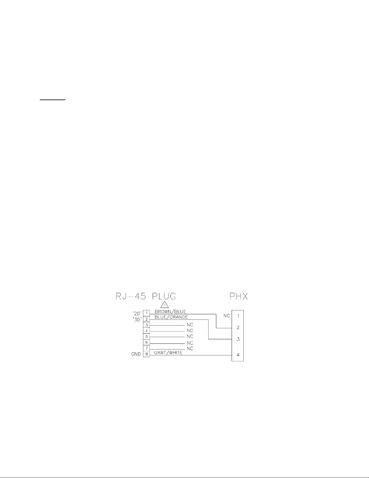
Connect four cables as described below. See Figure 5-1 for images.
Connect an 8-conductor cable from the BP1 J1 to the Alchemy ICMP-X GPI1-4
(this cable delivers the Fire Alarm output signals back to the projector).
Connect an 8-conductor cable from the BP1 J2 to the Alchemy ICMP-X GPO5-8.
Note: This cable controls the Screen Lights only. If there are no screen lights at this
particular theater, this cable is optional.
Connect an 8-conductor cable from the BP1 J3 to the Alchemy ICMP-X GPO1-4
(this cable carries the dimmer control signals from the projector to the BP1).
Connect an 8-conductor cable from the BP1 J4 to the Projector Cinema Controller
Board (CCB) GPO5-8 (this cable carries the Masking signals and XL-Mover signals
from the projector to the BP1).
Note: Depending on the projector model this last cable may have to be broken out at
the projector end for connection to the 37-pin “General Purpose I/O” connector as
shown in Figure 5-1. See Section 5.3 for more detailed information on making the
breakout connector. If a breakout cable isn’t required proceed to Section 6.

R000226 BP1 Automation 10 v.0.1 03/21
Figure 5-1

R000226 BP1 Automation 11 v.0.1 03/21
5.3 Making a Subminiature D-37 Breakout Cable
The easiest way to do this the following:
1. Cut the RJ45 connector off one end of a regular Ethernet patch cable and strip the eight
wires.
2. Terminate the 8 wires to a DB37 male breakout adapter such as the
ANMBEST_MD241,242 with no soldering or crimping needed. (see
https://www.amazon.com/ANMBEST-Solderless-Terminal-Connector-
Breakout/dp/B085H8MQ35/ref=sr_1_1_sspa
The connections should be made as shown in Figure 5-2.
DB37 Pin
→
RJ45 Pin RJ45 Color
13 1
32 2
14 3
33 4
15 5
34 6
16 7
35 8
Figure 5-2
Some IMB manufacturers, e.g. Dolby and GDC, provide a set of RJ45 to bare ends cables
in the box with the units, for use with the IMB’s GPIO ports. If you use one of these and
connect the unterminated end to a DB37 breakout adapter, keep in mind that the color
coding on these cables might not follow the regular T-568A color coding pattern
(illustrated above). You may need to use a multimeter to figure out which pin links to
which color.

R000226 BP1 Automation 12 v.0.1 03/21
6 CONFIGURING PROJECTOR IMB
6.1 Configuring Barco ICMP-X in Series 2 and 3 Projectors
These instructions apply to the use of the MiT BP1 automation board used with a Barco
Alchemy ICMP-X server in the following projector models:
DP2K-B and DP4K-B
DP2K-BLP and DP4K-BLP
DP2K-C and DP2K-CLP
DP2K-E
DP4K-L
DP2K-S and DP2K-SLP
The BP1 and this procedure may work using earlier versions of the Alchemy (ICMP and
ICMP+), but it has not been tested with them.
This section assumes that the reader is trained and competent to install and configure
these projectors, and is familiar with the service technician functions of the Barco
Communicator software, and the ICMP-X’s web UI.
Parts and Tools Needed
A complete BP1 automation system (or an IMC3-J automation retrofitted with the
BP1 JNIOR replacement board as described in the Appendix).
Three cat 5e or cat 6 Ethernet patch cables, of sufficient length to connect the
modified ICM3-J to the card cage of the projector, plus a custom-pinned RJ45 male
to DB37 male cable, per Section 5.3.
A Windows or Mac computer with at least one wired NIC, and Barco Communicator
version 5.15.0 or later installed.
The password to put Barco Communicator into service technician mode.
Procedure:
1. Connect the cables between the BP1 and the projector as described in Section 5.2, if
they aren’t already.
2. To configure the Media Server (ICMP-X) Automation, open Barco Communicator,
connect to the projector, and put Barco Communicator into service technician mode.
Navigate to Media Server →Automation →Cues, as illustrated in Figure 6-1.

R000226 BP1 Automation 13 v.0.1 03/21
Figure 6-1: Configuring the ICMP-X GPO Cues
3. Configure the GPIO cues that output from the ICMP-X and input to the BP1. First,
create a new cue group for ease of access. In this example, it has been called BP1.
Figure 6-2: Creating a new Cue Group

R000226 BP1 Automation 14 v.0.1 03/21
4. Once you have created the new group for the cues, click Add. You will now create the
five GPO cues that the BP1 can accept: Dimmer Mid, Dimmer Down, Dimmer Up, Screen
Lights On, Screen Lights Off.
Figure 6-3: Adding New Cues
5. Once you have added the new cue, you can then add the command to it that actually
fires the GPO.
Figure 6-4

R000226 BP1 Automation 15 v.0.1 03/21
The commands should be the same for all of the five GPO cues you create. The
command should be “Pulse Up”, and the duration 500 milliseconds. You will change the
output according to which function the cue performs, as shown in Figure 6-5.
GPO
Output
Function
1 Dimmer Mid
2 Dimmer Down
3 Dimmer Up
GPO 4 is not used by the BP1
5 Screen Lights On
6 Screen Lights Off
GPO 7 and 8 are not used by the BP1
Figure 6-5
Configuring the ICMP-X GPI Cues
6. Next, create the two GPI cues that the ICMP-X receives from the BP1. These handle
the fire alarm functions. They enable the show to be stopped or paused automatically
when the fire alarm activation signal is sent, and then restarted when the “all clear” signal
is sent from the fire alarm system, via the BP1.
In the cue editor, go to the Input Cues tab, and then press Add.
Figure 6-6

R000226 BP1 Automation 16 v.0.1 03/21
7. Next define the GPI behavior that triggers the action.
Figure 6-7
The choice of up or down will depend on the configuration of the fire alarm inputs to the
BP1. If the fire alarm input (to the BP1) mode is set to PULSE, then the GPI to the ICMP-
X should be configured as “On Input X Up.” If the fire alarm input is set to HOLD, then the
GPI to the ICMP-X should be “On Input 1 Down.” You should also ensure that the mode
jumper is set correctly on the BP1 board, as shown in Figure 6-8.
Figure 6-8

R000226 BP1 Automation 17 v.0.1 03/21
8. The next step is to configure what the ICMP-X will actually do in response to receiving
the GPI cue. This is done by adding commands to the cue in the same way that GPO
output commands were added to the output cues.
Figure 6-9
Figure 6-10

R000226 BP1 Automation 18 v.0.1 03/21
The command editor window allows you to specify which device the command goes to
(projector, player, or any other output device configured in the ICMP-X), the actual
command sent, and a delay in milliseconds from the cue being fired until the command is
sent. The delay function can be used to sequence multiple commands within a cue.
In this example, a signal received on GPI 1 (fire alarm active) will cause DCP playback to
be paused, and then, half a second later, the projector’s dowser to close. How you select
and configure these commands will depend on how you want the fire alarm procedure to
work in your theater.
After this is done, repeat the process for GPI 2. You will configure the cues according to
the actions shown in Figure 6-11.
GPI Input Function
1 Fire alarm active
2 Fire alarm released or
cleared
GPI 3 through 8 are unused by the BP1
Figure 6-11
Configuring the Projector GPO Cues
9. Navigate to Automation →GPO Status.
Figure 6-12
LOW
TOGGL

R000226 BP1 Automation 19 v.0.1 03/21
Now select GPO 5 through 8 in turn, and ensure that the default position is set to LOW. If
you want to test the action of each GPO, press the TOGGLE button. You should hear a
relay click on the BP1 board and see its corresponding indicator LED illuminate briefly.
10. Once the GPOs are configured correctly, you now need to add the commands to
trigger them to the projector’s preset macros that require their use. The four projector
GPO functions that the BP1 uses to trigger external devices are shown in Figure 6-13.
GPO
Output
Function
GPI 1 through 4 are not used by the
BP1
5 Masking open (to scope)
6 Masking closed (to flat)
7 XL Mover to 2D position
8 XL Mover to 3D position
Figure 6-13
If this is a 2D-only house and no XL Mover is installed, you can ignore 7 and 8.
11. Navigate to Configuration →Presets, and then click the edit button for the preset
macro you wish to modify. In this example, we are going to add the “XL Mover to 3D”
GPO command to one of the 3D macros.
Figure 6-14

R000226 BP1 Automation 20 v.0.1 03/21
12. Next, we add a GPO command to this macro.
Figure 6-15
GPO 8 is the “XL Mover to 3D” channel, and its action needs to be set to Toggle in order
for it to trigger the BP1. Remember to save the macro after adding the new command.
13. Given that the XL Mover takes about 10 seconds to move the 3D filter into position,
and we don’t want anything to be projected until this is complete, we will now move the
cue further up the macro, so that it executes as the first command after the video output
has been muted. This is done by highlighting the command entry and then moving it using
the arrow buttons, as in Figure 6-16.
This manual suits for next models
2
Table of contents