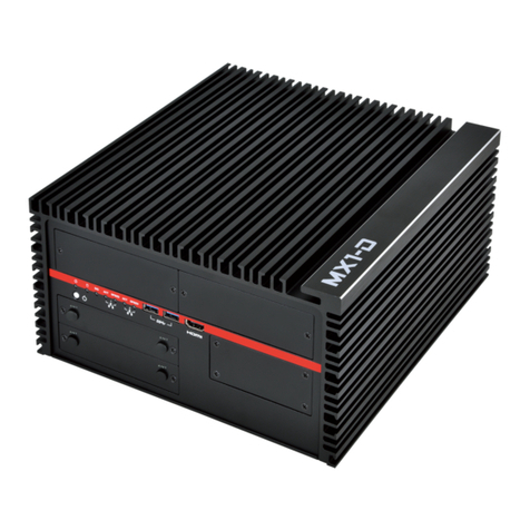
MiTAC Master Series User manual

MZ1-10ADP
User Manual
V1.1
Master Series Embedded System
Rugged GPU Computing System
Supports Intel® Raptor Lake-S / Alder Lake-S
Core-i Processor up to 125W

PREFACE
Copyright Notice
No part of this document may be reproduced, copied, translated, or transmitted in any form or by any
means, electronic or mechanical, for any purpose, without the prior written permission of MiTAC
Computing Technology Corporation. All information and specification provided in this manual are for
reference only and remain subject to change without prior notice.
Disclaimer
We reserve the right to make changes, without notice, to any product, including circuits and/or
software described or contained in this manual in order to improve design and/or performance. We
assume no responsibility or liability for the use of the described product(s) conveys no license or title
under any patent, copyright, or masks work rights to these products, and make no representations or
warranties that these products are free from patent, copyright, or mask work right infringement,
unless otherwise specified. Applications that are described in this manual are for illustration purposes
only. We make no representation or guarantee that such application will be suitable for the specified
use without further testing or modification.
Declaration of Conformity
FCC
This equipment has been tested and found to comply with the limits for a
class "A" digital device, pursuant to part 15 of the FCC rules. These limits
are designed to provide reasonable protection against harmful interference
when the equipment is operated in a commercial environment. This
equipment generates, uses, and can radiate radio frequency energy and, if
not installed and used in accordance with the instruction manual, may
cause harmful interference to radio communications. Operation of this
equipment in a residential area is likely to cause harmful interference in
which case the user will be required to correct the interference at him own
expense.
CE
This equipment is in conformity with the requirement of the following EU
legislations and harmonized standards. Product also complies with the
Council directions.

Safety Information
WARNING! / AVERTISSEMENT!
Always completely disconnect the power cord from your chassis
whenever you work with the hardware. Do not make connections
while the power is on. Sensitive electronic components can be
damaged by sudden power surges. Only experienced electronics
personnel should open the PC chassis.
CAUTION/ATTENTION
Always ground yourself to remove any static charge before touching
the CPU card. Modern electronic devices are very sensitive to static
electric charges. As a safety precaution, use a grounding wrist strap at
all times. Place all electronic components in a static-dissipative
surface or static-shielded bag when they are not in the chassis.
Safety Precautions
For your safety, please carefully read all the safety instructions before using the device. All cautions
and warnings on the equipment should be noted. Keep this user manual for future reference.
*Let service personnel to check the equipment in case any of the following problems appear:
The power cord or plug is damaged.
Liquid has penetrated into the equipment.
The equipment has been exposed to moisture.
The equipment does not work well or you cannot get it to work according to the user manual.
The equipment has been dropped and damaged.
The equipment has obvious signs of breakage on the surface.

Ordering Information
Model Number
Description
MZ1-10ADP-R680E
Rugged GPU Computing System with Intel® R680E Chipset
and 5 PCIe Slots.
2xDDR5 SO-DIMM 4800Mhz up to 64GB, 1xHDMI,
1xDisplayPort, 1xVGA, 2x2.5G LAN, 4xUSB3.2Gen2,
5xUSB3.2Gen1, 1xUSB2.0, 4xCOM, 5xPCIe slot, 9~48V
DC-in.
w/o AC adaptor
MZ1-10ADP-R680E-AC300
Rugged GPU Computing System with Intel® R680E Chipset
and 5 PCIe Slots.
2xDDR5 SO-DIMM 4800Mhz up to 64GB, 1xHDMI,
1xDisplayPort, 1xVGA, 2x2.5G LAN, 4xUSB3.2Gen2,
5xUSB3.2Gen1, 1xUSB2.0, 4xCOM, 5xPCIe slot, 9~48V
DC-in.
With 300W AC adaptor, and EU+US power cord
MZ1-10ADP-R680E-AC1000
Rugged GPU Computing System with Intel® R680E Chipset
and 5 PCIe Slots.
2xDDR5 SO-DIMM 4800Mhz up to 64GB, 1xHDMI,
1xDisplayPort, 1xVGA, 2x2.5G LAN, 4xUSB3.2Gen2,
5xUSB3.2Gen1, 1xUSB2.0, 4xCOM, 5xPCIe slot, 9~48V
DC-in.
With external 1000W PSU, power cables, and EU+US power
cord

Packing List
Item
Description
Q’ty
1
MZ1-10ADP Rugged GPU Computing System
1
2
Wall Mount Brackets (2 pcs in 1 set)
1
3
Screw Pack (For Wall Mount Bracket)
1
4
4-pin Terminal Block Power Connector (For DC Power Input)
2
5
2-pin Terminal Block Power Connector (For Remote Power Control)
1
6
GPU card to riser board power cable (3 types, 2 pcs for each type)
6
Optional Xpansion Modules and Accessories
Model Number
Description
MS-01IGN-S10
Vehicle Power Ignition Card, 12V/24V and Power ON/OFF Timing
Selectable
MZ1-01INFAN-A40
Internal System FAN with FAN duct Kit for A40 Card

CONTENTS
PREFACE ...............................................................................................................................................1
CHAPTER 1: INTRODUCTION ................................................................................................................8
1.1 Overview ................................................................................................................................8
1.2 Product Features ....................................................................................................................9
1.3 CPU Options .........................................................................................................................10
1.4 GFX/AI Card Options.............................................................................................................11
1.5 Hardware Specification ........................................................................................................12
1.6 Mechanical Specification .....................................................................................................16
1.7 System I/O Placement..........................................................................................................17
CHAPTER 2: DIP SWITCH SETTING AND PIN DEFINITION...................................................................19
2.1 Jumper and Internal Connector Overall Placement.............................................................19
2.2 DIP Switch Setting ................................................................................................................24
2.3 Internal Connector Pin Definition ........................................................................................26
2.4 External Connector Pin Definition........................................................................................28
2.5 Xpansion Module MS-01IGN-S10.........................................................................................32
CHAPTER 3: SYSTEM SETUP................................................................................................................34
3.1 CPU, Memory, and M.2 M Key Module Installation.............................................................34
3.2 M.2 B Key/E Key/mPCIe Module Installation.......................................................................37
3.3 PCIe Card Installation ...........................................................................................................38
3.4 RTC Battery Maintenance ....................................................................................................39
3.5 1000W PSU Cable Assembly ................................................................................................40
CHAPTER 4: BIOS SETUP.....................................................................................................................42
4.1 Main Page.............................................................................................................................42
4.2 Advance Page .......................................................................................................................45
4.3 Security Page........................................................................................................................61
4.4 Boot Page .............................................................................................................................67
4.5 Save & Exit Page ...................................................................................................................70
4.6 Event Logs.............................................................................................................................71

INTRODUCTION
This chapter provides the MZ1-10ADP Rugged GPU
Computing System product overview, including
features, hardware and mechanical specifications.
1

CHAPTER 1: INTRODUCTION
This chapter provides the MZ1-10ADP Rugged GPU Computing System product overview, including
features, hardware, mechanical specifications, and I/O placement.
1.1 Overview
MiTAC MZ1-10ADP, a revolutionary embedded system powered by Intel 12th/13th Gen Core-i
processor (up to 125W). With its unrivaled AI capabilities, this cutting-edge device takes innovation
to the next level. Optional with 2 x high-end NVIDIA GFX cards (up to 600W + 600W), the
MZ1-10ADP harnesses the immense parallel computing power of NVIDIA GPUs to deliver advanced
and multiplexed image processing for edge AI inference or machine learning tasks. Its expandable
design caters to the demands of high-performance applications while its rugged construction
ensures durability in even the harshest environments. Tailored for AI inference in factory
automation, intelligent transportation systems, smart cities, and smart retail, the MZ1-10ADP is
the pinnacle of embedded AI systems.
It revolutionizes AI and edge computing, offering numerous benefits for deploying the MZ1-10ADP
at the edge. Its integration of Intel's latest processor technology provides unparalleled processing
power, enabling real-time decision-making and accelerated AI inference at the edge. The optional
inclusion of two high-end NVIDIA GFX cards unlocks exceptional parallel computing, reducing
latency and dependence on the cloud. With expandability, it caters to evolving edge needs, while
its rugged construction ensures reliable operation in harsh environments. By choosing the MiTAC
MZ1-10ADP, you empower your edge infrastructure with cutting-edge AI capabilities, faster
insights, enhanced data privacy, and efficient edge deployments.

1.2 Product Features
MZ1-10FEP Rugged GPU Computing System features:
Intel 12th Gen Alder Lake-S Core i (Up to 125W)
SO-DIMM DDR5 x2 (Up to 4800/5600MHz and 64GB)
Support Dual high-end GFX cards (600W+600W)
Power Budget 1500W system power consumption
Hot Swappable 2.5/3.5” HDD Tray x4 & CFast slot
Exp.: PCIe x16/8, PCIe x4, PCIe x4, PCIe x8, PCIe x1
Wide Voltage Input from 9V to 48V

1.3 CPU Options
Processor Name
Cache
E Core
Base Clock
P Core
Base Clock
Boost Clock
Cores
Threads
TDP
13th Generation Intel® Raptor Lake-S
Intel® Core™ i9-13900 Processor
36M
1.50 GHz
2.00 GHz
5.60 GHz
8 + 16
32
65W
Intel® Core™ i9-13900E Processor
36M
1.30 GHz
1.80 GHz
5.20 GHz
8 + 16
32
65W
Intel® Core™ i9-13900TE Processor
36M
800 MHz
1.00 GHz
5.00 GHz
8 + 16
32
35W
Intel® Core™ i7-13700 Processor
30M
1.50 GHz
2.10 GHz
5.20 GHz
8 + 8
24
65W
Intel® Core™ i7-13700E Processor
30M
1.30 GHz
1.90 GHz
5.10 GHz
8 + 8
24
65W
Intel® Core™ i7-13700TE Processor
30M
800 MHz
1.10 GHz
4.80 GHz
8 + 8
24
35W
Intel® Core™ i5-13500 Processor
24M
1.80 GHz
2.50 GHz
4.80 GHz
6 + 8
20
65W
Intel® Core™ i5-13500E Processor
24M
1.50 GHz
2.40 GHz
4.60 GHz
6 + 8
20
65W
Intel® Core™ i5-13500TE Processor
24M
1.10 GHz
1.30 GHz
4.50 GHz
6 + 8
20
35W
Intel® Core™ i3-13100 Processor
12M
-
3.40 GHz
4.50 GHz
4
8
60W
Intel® Core™ i3-13100E Processor
12M
-
3.30 GHz
4.40 GHz
4
8
60W
Intel® Core™ i3-13100TE Processor
12M
-
2.40 GHz
4.10 GHz
4
8
35W
12th Generation Intel® Alder Lake-S
Intel® Core™ i9-12900 Processor
30M
1.80 GHz
2.40 GHz
5.10 GHz
8 + 8
24
65W
Intel® Core™ i9-12900E Processor
30M
1.70 GHz
2.30 GHz
5.00 GHz
8 + 8
24
65W
Intel® Core™ i9-12900TE Processor
30M
1.00 GHz
1.10 GHz
4.80 GHz
8 + 8
24
35W
Intel® Core™ i7-12700 Processor
25M
1.60 GHz
2.10 GHz
4.90 GHz
4 + 8
20
65W
Intel® Core™ i7-12700E Processor
25M
1.60 GHz
2.10 GHz
4.80 GHz
4 + 8
20
65W
Intel® Core™ i7-12700TE Processor
25M
1.00 GHz
1.40 GHz
4.60 GHz
4 + 8
20
35W
Intel® Core™ i5-12500 Processor
18M
-
3.00 GHz
4.60 GHz
6
12
65W
Intel® Core™ i5-12500E Processor
18M
-
2.90 GHz
4.50 GHz
6
12
65W
Intel® Core™ i5-12500TE Processor
18M
-
1.90 GHz
4.30 GHz
6
12
35W
Intel® Core™ i3-12100 Processor
12M
-
3.30 GHz
4.30 GHz
4
8
60W
Intel® Core™ i3-12100E Processor
12M
-
3.20 GHz
4.20 GHz
4
8
60W
Intel® Core™ i3-12100TE Processor
12M
-
2.10 GHz
4.00 GHz
4
8
35W
Intel® Pentium® G7400E Processor
6M
-
3.60 GHz
-
2
2
46W
Intel® Pentium® G7400TE Processor
6M
-
3.00 GHz
-
2
2
35W
Intel® Celeron® G6900E Processor
4M
-
3.00 GHz
-
2
2
46W
Intel® Celeron® G6900TE Processor
4M
-
2.40 GHz
-
2
2
35W

1.4 GFX/AI Card Options
Model Name
Display
Memory
CUDA
TDP
NVIDIA A40 48GB
*with optional fan and fan duct kit
3 x DP1.4a
48 GB GDDR6
10,752
300W
NVIDIA RTX 6000 Ada Gen.
4 x DP1.4a
24 GB GDDR6
18,176
300W
NVIDIA RTX A6000 48GB
4 x DP1.4a
48 GB GDDR6
10,752
300W
NVIDIA RTX A5500 24GB
4 x DP1.4a
24 GB GDDR6
10,240
230W
NVIDIA RTX A5000 24GB
4 x DP1.4a
24 GB GDDR6
8,192
230W
NVIDIA RTX A4500 20GB
4 x DP1.4a
20 GB GDDR6
7,168
200W
NVIDIA RTX 4000 SFF Ada Gen. 20GB
4 x mDP1.4a
20 GB GDDR6
6,144
70W
NVIDIA RTX A4000 16GB
4 x DP1.4a
16 GB GDDR6
6,144
140W
NVIDIA RTX A2000 12GB
4 x mDP1.4
12 GB GDDR6
3,328
70W
NVIDIA Quadro T1000 8GB
4 x mDP1.4
8 GB GDDR6
896
50W
NVIDIA Quadro T1000 4GB
4 x mDP1.4
4 GB GDDR6
896
50W
NVIDIA Quadro T400 4GB
3 x mDP1.4
4 GB GDDR6
384
30W
Leadtek RTX 4090 AI Blower 24GB
1 x HDMI2.1
3 x DP1.4a
24 GB GDDR6
16,384
450W
Leadtek RTX 4080 AI Blower 16GB
1 x HDMI2.1
3 x DP1.4a
16 GB GDDR6
9,728
320W
Leadtek RTX 4070 AI BLOWER 12GB
1 x HDMI2.1
3 x DP1.4a
12 GB GDDR6
5,888
200W
Leadtek RTX 3060 Classic 12GB
(LHR)ver.B
1 x HDMI2.1
3 x DP1.4a
12 GB GDDR6
3,584
170W

1.5 Hardware Specification
System
Processor
13th/12th Gen Intel® Raptor Lake-S/Alder Lake-S
Core i9/i7/i5/i3/Celeron/Pentium (Up to 125W)
Chipset
Intel® R680E
Memory
2 x 262-pin SO-DIMM / DDR5 4800/5600* MHz / Max. 64 GB (Non-ECC)
*13th Gen Intel Raptor Lake-S Core i9/i7 SKUs can support up to 5600MHz
Audio
Realtek® ALC888S
Super I/O
Nuvoton NCT6126D
LAN
Intel® i225LM Gigabit (10/100/1000/2500 Mb/s) LAN
Intel® i225V Gigabit (10/100/1000/2500 Mb/s) LAN
TPM IC
Nuvoton NPCT750AAAYX TPM2.0
Expansion
M.2 3042 / 3052 / 2242 / 2260 / 2280 B key (USB3.0, SATAIII, *PCIex1) w/
SIM slot*2
M.2 2230/ 2242 / 2260 / 2280 M key (PCIex4 NVME, SATAIII)
M.2 2230 E key (CNVi, PCIex1, USB 2.0)
Mini PCIe Full size*2 (USB2.0 / SATAIII / PCIex1) w/ SIM slot*2
Hot Swappable 2.5” HDD Tray*2, 3.5” HDD Tray*2
Removable CFast slot*1
PCIe Slot#1: PCIe x16 or PCIe x8 (switch by jumper setting) in PCIex16
physical connector
PCIe Slot#2: PCIe x4 in PCIex16 physical connector
PCIe Slot#3: PCIe x4 in PCIex16 physical connector
PCIe Slot#4: Blank or PCIe x8 (switch by jumper setting) in PCIex16
physical connector
PCIe Slot#5: PCIe x1 in Gen3 open-ended connector
Xpansion header for Optional Vehicle Power Ignition Xpansion
“MS-01IGN-S10” for delay power on/off
BIOS
AMI
Front I/O
4-pin Terminal Block x2 for power connectors
1 x Removable CFast Slot
SIM slot x4 (with door plate, mapping to 2 x mPCie and 1 x M.2 B Key
slots)
Side I/O
2 x Hot Swappable 2.5” HDD Tray (support 7-9.5mm height)
2 x Hot Swappable 3.5” HDD Tray

Rear I/O
Power/HDD LED
Power ON/OFF button
3 x RS232 (support power 5V/12V)
1 x RS232/422/485 (support power 5V/12V)
1 x DB37 connector for 32-bit DIO
1 x HDMI 2.0b
1 x VGA
1 x DisplayPort 1.4
2 x 2.5G RJ45 LAN Ports
4 x USB3.1 Gen2
4 x USB3.1 Gen1
2 x USB2.0
1 x Line out, 1 x Mic-in
5 x PCIe Slot
1 x Remote power on/off 2-pin terminal block
6 x Antenna SMA Hole with cap
Internal I/O
1 x USB3.2 Gen1 TYPE A
1 x USB2.0 TYPE A
4 x 8PIN PEG Header
Battery Holder with RTC Coin Battery
Clear CMOS switch
POWER REQUIREMENT
Power Input
9~48V Wide Range DC Input w/ Terminal Block Connectivity
Power Adaptor
Optional 300W/1000W AC to DC PSU
MECHANICAL
Thermal Design
Fan
Mounting
Wallmount
Dimension
(W X D X H)
264 x 415 x 256mm
Weight
13kg (28.7 lb)
ENVIRONMENTAL
Operating
Temperature
-40°C ~ 60°C (w/ 65W CPU, w/o GPU card)
-40°C ~ 50°C (w/ 80W CPU, w/o GPU card)
-40°C ~ 40°C (w/ 125W CPU, w/o GPU card)
*Please consult with your sales contact window about the Operating
Temperature of GPU Card Configurations / -40°C ~ 70°C (w/ 35W CPU,
w/o GPU card)
*Max OT limit -10°C w/ dual GPU card / with 0.7m/s Air Flow and Wide
Temperature Memory/Storage

Storage
Temperature
-40 ~ 85°C (-40 ~185°F)
Operating
Humidity
10% ~ 90% R/H (Non-condensing)
Storage Humidity
10% ~ 95% @85°C non-condensing
Vibration
Resistance
MIL-STD-810H, Follow Method 514.8C-I Category 4 for Truck
Shock Resistance
MIL-STD-810H 516.8 procedure I - functional shock, Operating 20G, 11ms
(Follow IEC 60068-2-27 half sine)
Certification
CE, FCC class A
OS
OS Support
Windows® 11 64bit, / Windows® 10 IoT LTSC 64bit (LTSC 2021) / Ubuntu
22.04

*Note1: Please make sure that the power consumption is in the spec of the
power supply output capability from AC adaptor (300W or 1000W). Please
choose the suitable AC adaptor for your application.
AC/DC 24V/12.5A, 300W Terminal Block Power Adaptor
AC/DC 48V/9.20.8A, 1000W Power Supply
*Note2: The safety ambient operating temperature is 40 degree C if the
external AC adapter model: EA13001N will be placed in the same high
temperature area with the embedded system.
*Note3: CAUTION - Lithium battery is included in this embedded system.
Please do not puncture, mutilate, or dispose of battery in fire. There will be
danger of explosion if battery is incorrectly replaced. Replace only with the
same or equivalent type recommended by manufacturer. Dispose of used
battery according to manufacturer instructions and in accordance with your
local regulations.
*Note4: Please read the BIOS release note before re-flashing BIOS. If the
BIOS notes mention the BIOS will be loaded default after re-flashing BIOS,
please check the BIOS setting again before boot up. For example,
inconsistent RAID setting might cause system boot up issue.
*Note5: When MZ1-10ADP is installed with PCIe GFX card, the BIOS setup
menu will only have display output via external graphic card.

1.6 Mechanical Specification
MZ1-10ADP
Mechanical Dimension: 264 x 415 x 256mm
Maximum Dimension for single GFX card (System Fan put inside): 340 mm x 150 mm x 4 Slots

1.7 System I/O Placement

DIP SWITCH SETTING AND PIN DEFINITION
This chapter provides information about how to set up the
dip switch and use internal I/Os of MZ1-10ADP Rugged GPU
Computing System hardware.
2

CHAPTER 2: DIP SWITCH SETTING AND PIN DEFINITION
This chapter provides information about how to set up the dip switch, and use internal I/Os of
MZ1-10ADP hardware.
2.1 Jumper and Internal Connector Overall Placement
2.1.1 Main Board Top side placement
Item
Location
Interface
B1
COM1
RS232 5Px2_NP10
B2
COM2
RS232 5Px2_NP10
B3
COM3
RS232 5Px2_NP10
B4
COM4
RS232 5Px2_NP10
B5
M2M1
M2 key M: Pcie Gen4 x4, SATA SSD
B6
CPU1
Intel® Alder Lake Processor socket
B7
DIMM1
DDR5 So-DIMM socket
B8
DIMM2
DDR5 So-DIMM socket

2.1.2 Main Board Bottom side placement
Item
Location
Interface
R1
PWRBT2
Power button
R2
JPWRBT1
Power button at PCB Screw Terminal
Block,2P,3.5mm,R/A
R3
J55
Audio Jack: MIC IN + LINE OUT I/O
R4
J59
USB2.0 x2 I/O
R5
J43
USB3.0 x2 + RJ45 2.5G
R6
J42
USB3.0 x2 + RJ45 2.5G
R7
DP1
Display Port I/O
R8
J60
USB3.0 x2 high Rise I/O
R9
HD1
HDMI 1.4 4K 30 Hz
R10
J62
USB3.0 x2 high Rise I/O
R11
VGA1
VGA I/O
Item
Location
Interface
F1
MP_SIM1
Mini Pcie SIM card holder from mini Pcie Slot#1, #2
F2
M2B_SIM1
M2 keyB SIM card holder
F3
CF1
Audio Jack: MIC IN + LINE OUT I/O
Other manuals for Master Series
1
This manual suits for next models
4
Table of contents
Other MiTAC Industrial PC manuals
Popular Industrial PC manuals by other brands

FabiaTech
FabiaTech FX5635 user manual

Omron
Omron NY532-5400 troubleshooting manual

Moxa Technologies
Moxa Technologies DA-681-I-SP-CE Quick installation guide

DFI
DFI DS912-OT installation guide

Avalue Technology
Avalue Technology SID-10W9 Quick reference guide

IBASE Technology
IBASE Technology IB836 Series user manual