Norco BIS-6592LC User manual

ThanksforpurchasingourcomputerforLEDdisplaysystem.Weattachgreatimportancetothe
manual.Themoreyou understand themanual,themoreeasilyyou can install itThe
instructionsinthismanualwill facilitateyouroperationofthisLEDcontrol system
Aboutthismanual
Thismanual containsageneral description ofBIS-6592LCandthedetailed descriptionofits
functions,features,installation anddismountinginstructions,BIOSsettings,etc., whichhelps
youtousethisproductinaright way.
Symbols
Thisrepresentstheimportantinformation tofacilitateyouruseof thisproduct
Thissymbol tomakeyounoticethatitmaycausedamageordataloss,andtellyouhow
toadvoid suchproblems.
Thissymbolindicatesthatoperationmayleadtopropertyloss orbodilyinjury.
SafetyInformation
Thisinformation canhelp youtousetheproductsafely.Pleasestricklyfollowthelabeled
warningsandintructionsgiven.Wefocusonthecustomer ssafety.The productswedevelop
baseonsafetyand availability.However,Powerlinesandotherpartsthatthemotherboard
containedmaycauseapotentialrisk in thecaseofimproperinstalling.Theymayresultinbodily
injuryorpropertyloss. Pleasefollowthemanual step bystep toavoid thesehazards.
Validity
Theceaseless upgradingofcomputerstructure,componentsandaccessoriesguaranteesthe
superiorityandsuperbqualityofthecomputer,therefore,youmayfind somefeaturesofyour
NORCOcomputersisnotinaccordwiththedescription in thismanual.NORCOreservesthe
right tomakechanges,withoutpriornotice,
Disclaimer
Except fortheaccessoriesattached totheproductasspecified herein,what iscontained inthis
usermanualdoesnotrepresentthecommitmentsofNORCOCompay.NORCOCompany
revervestherighttorevisethisUserManual,withoutpriornotice,andwill notbeheldliablefor
anydirect,indirect,intended orunintended lossesand/orhiddendangersduetoinstallationor
improperoperation.

Content
Chapter1ProductIntroduction.............................................................................1
1.1Overview...........................................................................................................................1
1.2Product Specification........................................................................................................1
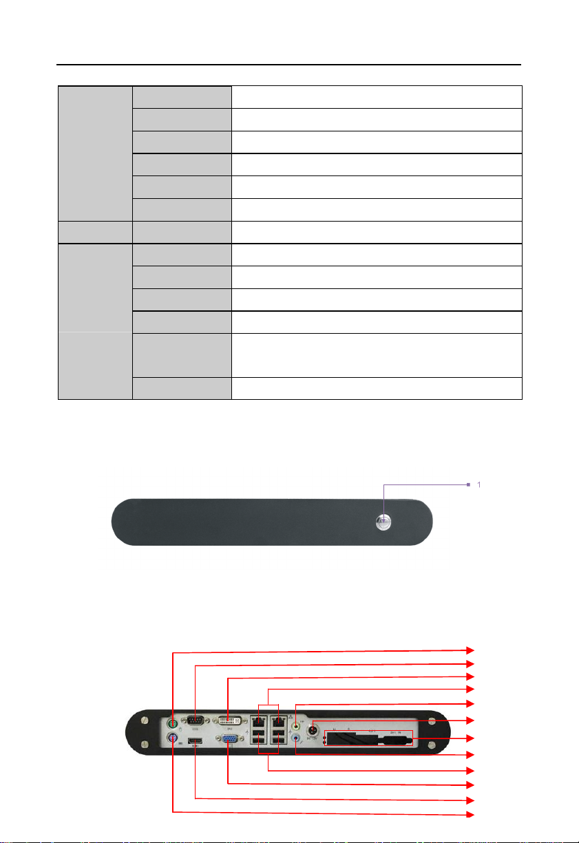
1.3Product IndicatorDiagram................................................................................................2
Chapter2MotherboardDescription......................................................................4
2.1InterfaceLocationandDimension...................................................................................4
2.2InstallationSteps...............................................................................................................4
2.3Install CPU........................................................................................................................5
2.4Install SO-DIMM...............................................................................................................6
2.5JumperSettings................................................................................................................6
2.5.1CMOSClear/Hold JumperSetting JCC)........................................................6
2.5.2COM2JumperSetting J7, J8, J9)....................................................................7
2.5.3LVDSRated VoltageSelect Jumper J2)...........................................................8
2.6InterfacesDescription.......................................................................................................9
2.6.1SATAandSATAPowerInterface SATA1, SATA2, J6).....................................9
2.6.2CF CardSocket Compact Flash)....................................................................10
2.6.3Serial Ports COM1, COM2, COM3-6)............................................................11
2.6.4DisplayInterfaces VGA,TV-OUT, HDMI,DVI,LVDS)...................................13
2.6.5LVDSBacklightControl andVoltageSelect J1).............................................15
2.6.6USB &LANPorts USB_LAN1,USB_LAN2,USB_1,USB_2).........................16
2.6.7Keyboard&MouseConnector PS/2).............................................................18
2.6.8InfraredTransmission Interface IRDA)...........................................................19
2.6.9General PurposeInput/Output GPIO)............................................................19
2.6.10PowerInterface(PWR)......................................................................................20
2.6.11FANConnector GMCHFAN, CPUFAN)........................................................21
2.6.12AudioInterface(AUDIO).....................................................................................22
2.6.13Front Panel Connector JFP).........................................................................22
2.6.14SO-DIMM DIMM1, DIMM2)..........................................................................24
2.6.15PCIESlot............................................................................................................24
2.6.16Mini PCIE MINI_PCIE1,MINI_PCIE2,J3,J4)...............................................24
Chapter3ComputerInstallationandUse.............................................................25

3.1Install ComputerPeripheral Accessories.......................................................................25
3.1.1DVI InterfaceConnection.....................................................................................25
3.1.2COMDeviceConnection.....................................................................................25
3.1.3PS/2KeyboardandMouseConnection..............................................................25
3.1.4PowerCableConnection.....................................................................................26
3.2Install ComputerSoftware..............................................................................................26
3.2.1Install OperatingSystem.............................................................................................26
3.2.2Install Driver..........................................................................................................26
3.3BIS-6592LCBIOSSetup................................................................................................26
AMIBIOSFlash....................................................................................................................26
AMIBIOSDescription...........................................................................................................27
BIOSSettings........................................................................................................................27
3.1MainMenu......................................................................................................................28
3.2Advanced Menu..............................................................................................................29
3.2.1CPUConfiguration...............................................................................................30
3.2.2IDEConfiguration.................................................................................................31
3.2.3SupperIOConfiguration......................................................................................33
3.2.4HardwareHealthConfiguration...........................................................................34
3.2.5ACPIConfiguration...............................................................................................35
3.2.6AHCIConfiguration..............................................................................................37
3.2.7ASFConfiguration................................................................................................39
3.2.8MEBIOSExtension Configuration......................................................................39
3.2.9IntelVT-dConfiguration.......................................................................................41
3.2.10MPS Configuration.............................................................................................42
3.2.11APMConfiguration..............................................................................................42
3.2.12USBConfiguration.............................................................................................44
3.2.13OnboardLANOptionROM...............................................................................46
3.3PCIPnPMenu................................................................................................................47
3.4BootMenu.......................................................................................................................49
3.4.1Boot SettingConfiguration...................................................................................50
3.4.2Boot DevicePriority..............................................................................................52
3.4.3HardDiskDrives..................................................................................................53
3.5SecurityMenu.................................................................................................................54

3.6ChipsetMenu..................................................................................................................55
3.6.1NorthBridgeConfiguration..................................................................................56
3.6.2SouthBridgeChipset Configuration....................................................................58
3.7ExitMenu........................................................................................................................60
Chapter4Install&ReplaceComponents.............................................................62
4.1RemoveComputerCover...............................................................................................63
4.2ReplaceDIMM................................................................................................................64
4.3Install CF Card................................................................................................................64
4.4MountingBracket............................................................................................................65
Appendix............................................................................................................66
Appendix1: DriverInstallation..............................................................................................66
Appendix2: Watchdog ProgrammingGuide.......................................................................67
Appendix3: GPIOInstruction...............................................................................................69
Appendix4: Glossary............................................................................................................70

PackingList
Thanksforpurchasing NORCOproducts. Pleasecheck your
packagecarefullyaccording tothe checklist below.If youfindany
componentslost ordamaged, pleasecontact yourretailer.
■BIS-6592LC
■UserManual
■DriveDisk
■DVI Cable
■PowerAdaptor
■Wall-MountKit
■Screw
1pcs
1pcs
1pcs
1pcs
1set
1set
1bag

Chapter1 Product Introduction

BIS-6592LCLEDScreen Control HardwarePlatformsupporting1080PHDDisplay
1
Chapter1ProductIntroduction
1.1Overview
BIS-6592LCisIntel GM45based fanless solution speciallydesigned fordigital signage
applications. “ICEFIN”enclosure,compactandslim,utilizingIntelPenryn/Core2Duo
/Celercon Mprocessors.Itoffershighperformancewithindustrial-gradereliability.2xDDR3
800/1066MHzSO-DIMM,onboardmemoryupto8GB.DVI,VGAandHDMIdisplayoutput.
SystemalsofeaturesrichI/O:1xCOM,4xUSB2.0,1xCF,1xMiniPCIeSSD,1x2.5”SATA,
2xLAN,1xKB, 1xMS, 1xMicin,1xLineout,1xMiniPCIeand1xPCILEDcontrol cardreserve
location.Withflexibleexpansionandmultipledisplay,BIS-6592LCiswidelyusedinsuch
applicationsasadvertising,LCD LargeScreen,RailTransportation,self-serviceterminals,
Information Control,Video Surveillance,etc.
1.2ProductSpecification
Model BIS-6592LC
Platform Intel
Color Black
Dimension 355mm×194mm×54.5mm(W×D×H)
Structure ICEFINfanless enclosure
Chassis
MaterialAluminiumalloy
Model MITX-6892
Processor SocketPIntel Penryn/Core2Duo/CeleronM
Chipset Intel GM45+ICH9BM
Motherboard
Memory 2x204Pin SO-DIMMslotssupportDDR3
667/800/1066MHz, RAMupto8GB
CF 1xCF
SSD 1xMiniPCIeSSD(optional)
Storage
HDD 1x2.5"SATA
Network Intel 82567LM/82574L,10/100/1000Mbps,2xLAN
USB 4xUSB2.0
SerialPort 1xRS232(DB9)
System
Features
Display 1xVGA,1xDVI-D,1xHDMI

BIS-6592LCLEDScreen Control HardwarePlatformsupporting1080PHDDisplay
2
Cooling System
1xCPUFAN
Audio 1xMic-in,1xLine-out
Expansions 1xPCILEDControl cardreservelocation
SystemLED N/A
SystemControl
PowerON/OFF Switch
PS/2 1xKB,1xMS
PowerPowerSupply DC +12Vpoweradaptor
Mounting DesktoporWall Mount
OperatingTemp
0~55
StorageTemp -40 ~80
RelativeHumidity
5%~95% relativehumidity,non-condensing
Operating
Vibration 0.5grms/5~500Hz/randomoperating
Reliability
EMC CE/FCC Class B
1.3ProductIndicatorDiagram
1BIS-6592LCFrontView
1. PowerButton
2BIS-6592LCRearView
2
3
4
10
5
6
8
9
7
11
13
12

BIS-6592LCLEDScreen Control HardwarePlatformsupporting1080PHDDisplay
3
2:Mouse
4:DVI
6:SPEAKER-OUT
8:LEDController
10:4xUSB2.0
12:HDMI
3: COM
5:2xLAN
7:DC 12V
9:MIC-IN
11:VGA
13:Keyboard

Chapter2 Motherboard Description

BIS-6592LC LEDScreen ControlHardwarePlatformsupporting1080PHD Display
4
Chapter2MotherboardDescription
2.1InterfacesLocation &Dimension
The followingpictureshowsthefrontpanel interfaceslocationandthedimensionoftheboard
MITX-6892(boardrearwith1xSO-DIMMslot,1xCFcardsocketand1xMINI-PCIEslot.).
Pleasepayattentiontotheinstallationprocedures.Improperinstallationofanycomponents
willleadtosystemmalfunction.
Note:Beforeinstallation, wemustputon theanti-staticgloves,in casethatthestatic
electricitycausesdamageto themotherboard.
MITX-6892Dimension
2.2Installation Steps
Pleasefollowthestepsbelowtoassembleyourcomputer
1. Refertothemanual andsetupall thejumpersofBIS-6592LC.

BIS-6592LC LEDScreen ControlHardwarePlatformsupporting1080PHD Display
5
2. InstallCPU
3. InstallMotherboard
4. Intall otherexpansion cards
5. Connectallsignal cable,powercable, panel control cableandpowersupply
6.StartthecomputerandcompletetheBIOSsetting
Keycomponentsofthismotherboard areintegrated circuit, andthesecomponents
will beeasilydamagedbyelectrostaticinfluence. So, beforeinstalling the
motherboard, youshouldalways keep thefollowingprecautionsin mind:
1. Holdtheboardbyedges,don ttouchanycomponentsorplugand socketpins
2.Wearanti-staticgloves/wriststrapwhiletouchingtheintegrated circuitcomponents,suchas
CPU, RAM,etc.
3.Put thoseunusedoruninstalledcomponentsinstaticshieldingbagsortrays
4.Pleasefirst checkthepowerswitchisoffbeforeconnectingthepowerplug
2.3InstallCPU
PleasefollowthestepsbelowtoinstallCPU:
1.UsescrewdrivertounscrewtheCPU,makingCPU “Locked”to “Unlock”, illustrated as
below:
2.HoldtheCPUbybothsides,then aligntheCPUPin1(agoldentrianglemark)withthenotch
on CPUsocketand inserttheCPUintothesocket. Checktheconnection andthen lockthe
CPUbyusingthescrewdriver.
Note:PleasemakesuretheCPUyouused matchesthemotherboard.Aftersystembootsup,
BIOSwill autodetecttheCPUtypeanditsfrequency.BIOSsettingswillnotallowusersto
adjust theCPUfrequencydoubling.Toensurethesystemworksstably,wedon trecommend
youtomaketheCPUoverlocking. Rightnow,mostIntelCPUfrequencydoubling isfactory
defaultasunchangeable.

BIS-6592LC LEDScreen ControlHardwarePlatformsupporting1080PHD Display
6
2.4InstallSO-DIMM
Boardwith2xDDRIII SO-DIMMslots.Plskeep following twopointsinmindtoinstall
SO-DIMM:
1. First,pleasealginthenotchof thememorybankwiththenotchon thesocketandpress the
memorybankslowlyintothesocket.
2. Pleasechoosethepropermemorybankthatmatchesyourmotherboard
2.5JumperSettings
Pleaserefertofollowing instructionstodojumpersettingsbeforeinstalling yourhardware
devices.
Remark: HowtoidentifythePIN1ofalljumpersandinterfaces:Pleaseobservethewordmark
onthesideoftheplugsocket, whichwillbea “1”orboldlineortriangularsymbol; Andplease
lookat thebackofPCB,eachwithasquareshapewillbethePIN1;andall thejumpers PIN1
haveawhitearrowon theside.
2.5.1CMOSClear/HoldJumperSetting JCC)
CMOSispowered bytheonboardbuttoncell.ClearCMOSwillleadtopermanentelimination
of previoussystemsettingsandback totheoriginal systemsetting (factorydefault).
Steps: 1)Turnoffthecomputeranddisconnect thepowersupply
2)UseJumperCap JCCPin1-2shortfor5~6sec.Then restorethedefaultsetting
withPin2-3connected
3)Turnon thecomputer,thenpress “DEL”keytoenterBIOSsetting andreload
optimaldefaults.
4)SaveandExit

BIS-6592LC LEDScreen ControlHardwarePlatformsupporting1080PHD Display
7
Setting JCC
1-2 BIOS backtointialization(factorydafault)
2-3 NormalStatus, Systemdefault
DonotclearCMOSwhen thecomputorispoweron, otherwise,itwillcause
damageto themotherboard!
2.5.2COM2JumperSetting J7,J8,J9)
J7,J8,J9jumpersareused toconfigureCOM2transmission mode.COM2supportsRS
232/RS422/RS485. SystemdefaultRS232.

BIS-6592LC LEDScreen ControlHardwarePlatformsupporting1080PHD Display
8
2.5.3LVDSRated Voltage SelectJumper J2)
BeforeusingtheLVDS,pleasefirst check theratedoperatingvoltage. J2isselected byLVDS
rated voltage.
COM2RS232 Default)
COM2RS422 COM2RS485
J7 3-54-6 J7 1-32-4 J7 1-32-4
J8 3-54-6 J8 1-32-4 J8 1-32-4
J9 1-2 J9 3-4 J9 5-67-8

BIS-6592LC LEDScreen ControlHardwarePlatformsupporting1080PHD Display
9
Setting J2
1-2 VCC
2-3 VCC3
2.6InterfacesDescription
Pleasereadthefollowing instructionscarefullybeforeyouconnectingtheexternal
connectorsin caseofanydamagecaused tothemotherboard.
2.6.1SATA&SATAPowerInterface SATA1, SATA2, J6)
Boardprovides2xSATAports.When using theseinterfaces,HDD ispower-upthroughthe
SATApowerinterfacewithanadaptercable

BIS-6592LC LEDScreen ControlHardwarePlatformsupporting1080PHD Display
10
SATA:
Pin SignalName
1 GND
2 TX+
3 TX-
4 GND
5 RX-
6 RX+
7 GND
J6 SATAPowerInterface):
Pin SignalName
1 +12V
2 GND
3 VCC
4 GND
5 VCC3
2.6.2CFCardSocket CompactFlash)
Boardrearpanel withone50PinCFCardSocket supportsDMAmode.

BIS-6592LC LEDScreen ControlHardwarePlatformsupporting1080PHD Display
11
2.6.3Serial Ports COM1,COM2, COM3-6)
Boardprovides6xserial ports.COM1and COM2adoptIOchip.COM3-6adoptF81216AD.
Chip.COM1istheDB9interface.COM2isthe2x5Pininterface.COM2needstobe
converted intostandardDB9interfacetoconnectexternal devices.Userscan open orclose
theserial portsandselectitsIRQandIOaddress underBIOSsettings.
COM1&COM2supportRS232.COM2alsosupportsRS422/485.Userscan selectCOM2
transmissionmodebyCOM2jumpersetting.DetailsplsrefertoChapter2-2.5.2 “COM2
JumperSetting”.
COM1:
Pin SignalName
1 DCD
2 RXD
3 TXD
4 DTR
5 GND
6 DSR
7 RTS
8 CTS

BIS-6592LC LEDScreen ControlHardwarePlatformsupporting1080PHD Display
12
9 RI
COM2:
SignalName PinSignalName
DCD 1 2 DSR
SIN 3 4 RTS
SOUT 5 6 CTS
DTR 7 8 RI
GND 9 10 GND
COM2configured asRS232/RS422/RS485,Pinsdefined asbelow:
RS485 RS422 RS232 Pin RS232 RS422 RS485
DATA- TX- DCD 1 2 RXDTX+ DATA+
NC RX+ TXD 3 4 DTRRX- NC
GND GND GND 5 6 DSRNC NC
NC NC RTS 7 8 CTS NC NC
NC NC RI 9
COM3-6:
SignalName PinSignalName
HDCD#3 1 2 HDSR#3
HRXD3 3 4 HRTS#3
HTXD3 5 6 HCTS#3
HDTR#3 7 8 HRI#3
GND 9 10 GND
HDCD#4 11 12 HDSR#4
HRXD4 13 14 HRTS#4
HTXD4 15 16 HCTS#4
HDTR#4 17 18 HRI#4
GND 19 20 GND
HDCD#5 21 22 HDSR#5
HRXD5 23 24 HRTS#5
HTXD5 25 26 HCTS#5
HDTR#5 27 28 HRI#5
GND 29 30 GND
HDCD#6 31 32 HDSR#3

BIS-6592LC LEDScreen ControlHardwarePlatformsupporting1080PHD Display
13
HRXD6 33 34 HRTS#6
HTXD6 35 36 HCTS#6
HDTR#6 37 38 HRI#6
GND 39 40 GND
2.6.4DisplayInterfaces VGA, TV-OUT, HDMI,DVI, LVDS)
VGA:
Pin SignalName
Pin
SignalName
Pin SignalName
1 RED 6 GND 11 NC
2 GREEN 7 GND 12 SDA_R
3 BLUE 8 GND 13 HS_R
4 NC 9 VCC 14 VS_R
5 GND 10 GND 15 SCL_R
TV-OUT:
SignalName Pin SignalName
TV-DACA-OUT 1 2 GND
TV-DACB-OUT 3 4 GND
TV-DACC-OUT 5 6 GND
Table of contents
Other Norco Industrial PC manuals
Popular Industrial PC manuals by other brands

Xciel
Xciel XCRiPad user manual

Advantech-DLoG
Advantech-DLoG MPC 6 quick start guide

SYSTEM Electronics
SYSTEM Electronics COPILOT 15" MAINTENANCE and Operation manual

Automationdirect.com
Automationdirect.com D4-470 user manual

Avalue Technology
Avalue Technology SID-10W9 Quick reference guide

Nexcom
Nexcom NDiS B533 user manual

AXIOMTEK
AXIOMTEK tBOX322-882-FL Quick installation guide

IBASE Technology
IBASE Technology IB836 Series user manual

VeriFone
VeriFone Topaz XL Hardware installation guide

AXIOMTEK
AXIOMTEK eBOX625-312-FL Quick installation guide

Systec & Solutions
Systec & Solutions CONTROL 217 PC Instructions for use

Bull
Bull DPS 7000 Operator's guide