manuals.online logo
Brands
  1. Home
  2. •
  3. Brands
  4. •
  5. M-system
  6. •
  7. Media Converter
  8. •
  9. M-system M8BS-16U0 User manual

M-system M8BS-16U0 User manual

M8BS-16U0
EM-5490-U0 Rev.5P. 1 / 3
BEFORE USE ....
Thank you for choosing M-System. Before use, check the
package you received as below.
If you have any problems or questions with the product,
please contact M-System's Sales Office or representatives.
■ PACKAGE INCLUDES:
Installation base ..................................................... (1)
■ MODEL NO.
Check that model No. described on specification label is
exactly what you ordered.
■ INSTRUCTION MANUAL
This manual describes necessary points of caution when you
use this product, installation, connection and basic mainte-
nance procedures.
INSTRUCTION MANUAL
MODEL
M8BS-16U0
INSTALLATION BASE
(16 positions)
COMPONENT IDENTIFICATION
■ REAR VIEW
MOUNTING REQUIREMENTS mm (inch)
Specification
Label
465 (18.31)
4–M5 SCREW
50 (1.97)
A
B
C
D
Ch.1
INPUT**
A
B
C
D
Ch.16
INPUT**
PWR2
■ Power Supply Code R, K ■ Power Supply Code KK, L
4
5
FG
3
U
VAC POWER
PWR1
4
5
FG
3
U
VAC POWER
FG
U(+)
V(–) POWER
OUTPUT 1
3
2
1
A
B
C
D
Ch.1
INPUT**
A
B
C
D
Ch.16
INPUT**
+
–
OUTPUT 2
OUTPUT 1
OUTPUT 2
+
–
Ch.1
OUTPUT**
+
–
+
–
Ch.16
OUTPUT**
OUTPUT 1
+
–
OUTPUT 2
OUTPUT 1
OUTPUT 2
+
–
Ch.1
OUTPUT**
+
–
+
–
Ch.16
OUTPUT**
*
*For power code KK only.
**The input and output terminals are reversed for model M8YS/M8YS1.
Use either Output 1 or Output 2 terminal for the input.
TERMINAL CONNECTIONS
Connect the unit as in the connection diagram below, referring drawings in the following page.
■ CONNECTION DIAGRAM
M8BS-16U0
EM-5490-U0 Rev.5P. 2 / 3
■EXTERNAL DIMENSIONS mm (inch)
• M8BS-16U0-K, R
• M8BS-16U0-KK, L
1 2 3 4 5 6 7 8 9
10 11 12 13 14 15 16
123
CH1 CH8 CH9 CH16
CDCDCDCDCDCDCDCD
CH8CH1
ABABABABABABABAB CDCDCDCDCDCDCDCD
CH16CH9
ABABABABABABABAB
+–+–+–+–+–+–+–+–
+–+–+–+–+–+–+–+–
++
–+–+–+–+–+–+–
+–+
––+–+–+–+–+–+–
95 (3.74)
50 (1.97)
64–M3.5 INPUT TERMINALS
87 (3.43)
7.3(.29) 64–M3.5
OUTPUT TERMINALS
3–M3.5
POWER TERMINALS POWER LED
8.6 (.34)
17 (.67)
CT PROTECTOR (CTR)
440 (17.32)
465 (18.31)
480 (18.90)
7.3 (.29)
OUTPUT 2 TERM.
OUTPUT 1 TERM.
1 2 3 4 5 6 7 8 9
10 11 12 13 14 15 16
CH1 CH8 CH9 CH16
CDCDCDCDCDCDCDCD
CH8CH1
ABABABABABABABAB CDCDCDCDCDCDCDCD
CH16CH9
ABABABABABABABAB
+–+–+–+–+–+–+–+–
+–+–+–+–+–+–+–+–
++
–+–+–+–+–+–+–
+–+
––+–+–+–+–+–+–
PWR1PWR2
3
2
1
4
5
3
2
1
4
51
2
95 (3.74)
50 (1.97)
7.3(.29) 64–M3.5
OUTPUT TERMINALS
17 (.67)
CT PROTECTOR (CTR)
440 (17.32)
465 (18.31)
480 (18.90)
64–M3.5 INPUT TERMINALS
7.3 (.29)
5–M4
POWER TERMINALS
8.5
(.34)
*1
POWER UNITS
*2
POWER LED
135 (5.31)
87 (3.43)
POWER LED
*3
*1. PWR2 provided only for power code KK.
*2. For power code KK.
*3. For power code L.
OUTPUT 2 TERM.
OUTPUT 1 TERM.
M8BS-16U0
EM-5490-U0 Rev.5P. 3 / 3
CHECKING
1) Terminal wiring: Check that all cables are correctly
connected according to the connection diagram.
2) Power input voltage: Check voltage across the power
terminals.
3) Installation & environment
POINTS OF CAUTION
■ ENVIRONMENT
• When heavy dust or metal particles are present in the air,
install the installation base inside proper housing and venti-
late it.
• Do not install the base where it is subjected to continuous
vibration. Do not apply physical impact to the unit.
• Environmental temperature must be within 0 to 55°C or 32
to 131°F (0 to 50°C or 32 to 122°F for AC power) with relative
humidity within 30 to 90% RH in order to ensure adequate
life span and operation.
• Be sure that the ventilation slits are not covered with
cables, etc.
■ WIRING
• Do not install cables (power supply, input and output) close
to noise sources (relay drive cable, high frequency line, etc.).
• Do not bind these cables together with those in which noises
are present. Do not install them in the same duct.
■ AND ....
• The unit is designed to function as soon as power is
supplied, however, a warm up for 10 minutes is required for
satisfying complete performance described in the data sheet.
MAINTENANCE
For maintaining AC power supply types, Power Supply Units
are available as follows:
• 85 – 132V AC single power supply: HDC6-1
•
85 – 132V AC two independent power sources: HDC4-K-R
• 170 – 264V AC single power supply: HDC4-L-R
Power units' standard life is expected for 10 years with
average ambient temperature 35°C (95°F) and 1.0A load.
Contact M-System for use in extremely different conditions.
■
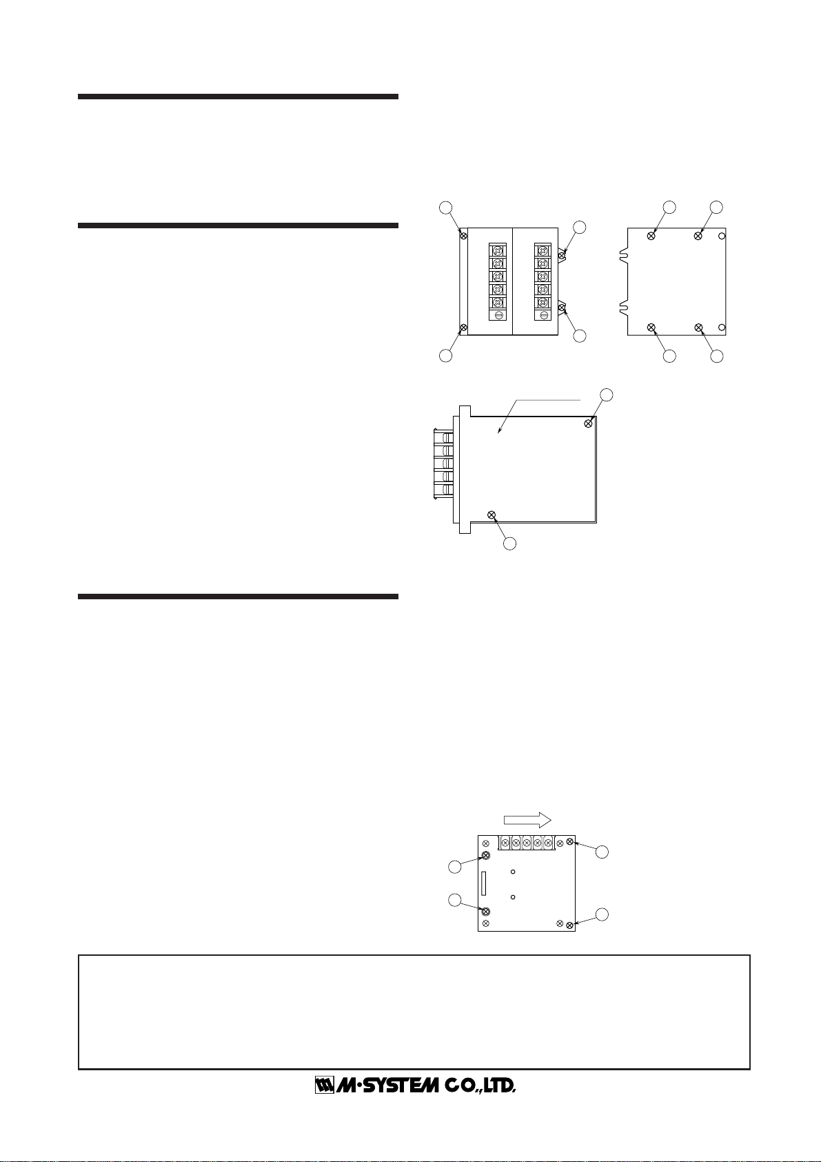
HOWTOREPLACETHEPOWERUNIT(powersuffixcode:KK,
L)
1) Prepare Power Unit (switching regulator) model HDC4-
K-R or HDC4-L-R.
2) Turn off the power supply connected to the Power Unit.
3) Remove the wire binding and wiring connected to the
terminal 1 – 2 and 4 – 5.
4) Loosen and remove the mounting screws A(4 places).
Remove also the screws Bbehind the base plate, fixing the
unit to be replaced.
5) Detach the Power Unit from the Installation Base.
6) Remove the mounting screws C(2 places) from the new
Power Unit.
7) Separate the new Power Unit from the mounting plate.
8) Attach the new Power Unit to the Installation Base and
tighten the screws in reverse order as explained above.
■
HOW TO REPLACE THE POWER UNIT (power suffix code: K)
1) Prepare Power Unit (switching regulartor) model HDC6-
1.
2) Turn off the power supply connected to the Power Unit.
3) Remove the wiring connected to the terminals 1 – 2 and 3.
4) Loosen and remove the mounting screws A(2 places).
Loosen the mounting screws B(2 places) and pull out the
Power Unit in sliding it to the direction pointed by the
arrow in the figure below.
5) Disconnect the connectors of the Power Unit.
6) Place the new Power Unit in reverse order as explained
above.
Caution: Check that the internal wiring does not get caught
between other objects when assembling.
A
A
A
A
B B
BB
5
4
3
2
1
5
4
3
2
1
C
Mounting Plate
C
A
B
C
1
2
3
4
5
: Mounting screws with
washer, M3 x 6 (4 pls.)
: Mounting screws with
washer, M3 x 5
(2 pls. per unit)
: Flat-head mounting
screws, M3 x 4 (+)
(2 pls.)
: 24V DC (+)
: 24V DC (–)
: FG
: AC power input (U)
: AC power input (V)
■SIDE VIEW OF THE POWER UNIT
■FRONT VIEW ■REAR VIEW
B
B
A
A
123
A
B
1
2
3
: Mounting screws with
washer, M3 x 6 (2 pls.)
: Mounting screws with
washer, M3 x 10L (2 pls.)
: AC power input (U)
: AC power input (V)
: FG
■FRONT VIEW
M-SYSTEM WARRANTY
M-System warrants such new M-System product which it manufactures to be free from defects in materials and workmanship during the 36-month period following the date that such
productwasoriginallypurchasedifsuchproducthasbeenusedundernormaloperatingconditionsandproperlymaintained,M-System'ssoleliability,andpurchaser'sexclusiveremedies,
under this warranty are, at M-System's option, the repair, replacement or refund of the purchase price of any M-System product which is defective under the terms of this warranty. To
submit a claim under this warranty, the purchaser must return, at its expense, the defective M-System product to the below address together with a copy of its original sales invoice.
THIS IS THE ONLY WARRANTY APPLICABLE TO M-SYSTEM PRODUCT AND IS IN LIEU OF ALL OTHER WARRANTIES, EXPRESS OR IMPLIED, INCLUDING ANY IMPLIED
WARRANTIES OF MERCHANTABILITY OR FITNESS FOR A PARTICULAR PURPOSE. M-SYSTEM SHALL HAVE NO LIABILITY FOR CONSEQUENTIAL, INCIDENTAL OR
SPECIAL DAMAGES OF ANY KIND WHATSOEVER.
M-System Co., Ltd., 5-2-55, Minamitsumori, Nishinari-ku, Osaka 557-0063 JAPAN, Phone: (06) 6659-8201, Fax: (06) 6659-8510, E-mail: [email protected]

Other M-system Media Converter manuals

M-system Mini-MW Series User manual

M-system

M-system Mini-MW Series User manual

M-system JPR2 User manual

M-system

M-system JPR2 User manual

M-system 18KVS User manual

M-system

M-system 18KVS User manual

M-system 18PE User manual

M-system

M-system 18PE User manual

M-system M8XM2 User manual

M-system

M-system M8XM2 User manual

M-system 18CE User manual

M-system

M-system 18CE User manual

M-system JPR2 User manual

M-system

M-system JPR2 User manual

M-system Mini-M M2AP User manual

M-system

M-system Mini-M M2AP User manual

M-system 18TG User manual

M-system

M-system 18TG User manual

M-system JARP2 User manual

M-system

M-system JARP2 User manual

M-system 17TG User manual

M-system

M-system 17TG User manual

M-system JFR2 User manual

M-system

M-system JFR2 User manual

M-system M8CTC User manual

M-system

M-system M8CTC User manual

M-system 18KTS User manual

M-system

M-system 18KTS User manual

M-system M80MS User manual

M-system

M-system M80MS User manual

M-system JFR2 User manual

M-system

M-system JFR2 User manual

M-system M8YV1 User manual

M-system

M-system M8YV1 User manual

M-system M8XV2 User manual

M-system

M-system M8XV2 User manual

M-system M8VS User manual

M-system

M-system M8VS User manual

M-system 18JV User manual

M-system

M-system 18JV User manual

M-system Mini-M M2PRU User manual

M-system

M-system Mini-M M2PRU User manual

M-system LK1 User manual

M-system

M-system LK1 User manual

M-system Mini-M M2RR User manual

M-system

M-system Mini-M M2RR User manual

M-system M8CT User manual

M-system

M-system M8CT User manual

Popular Media Converter manuals by other brands

elink LNK-IMC3011-SFP quick start guide

elink

elink LNK-IMC3011-SFP quick start guide

Planet GT-922 manual

Planet

Planet GT-922 manual

AVLink HRM-2212F user manual

AVLink

AVLink HRM-2212F user manual

red lion GCM23201 quick start guide

red lion

red lion GCM23201 quick start guide

Ntron 202MC Specifications

Ntron

Ntron 202MC Specifications

TV One C2-2855 quick start guide

TV One

TV One C2-2855 quick start guide

Black Box VSC-HDMI-SDI user manual

Black Box

Black Box VSC-HDMI-SDI user manual

Syba Sonic DSD user manual

Syba Sonic

Syba Sonic DSD user manual

Black Box V.24/X.21 user guide

Black Box

Black Box V.24/X.21 user guide

AVPro Edge AC-DA210-HDBT-KIT Operation manual

AVPro Edge

AVPro Edge AC-DA210-HDBT-KIT Operation manual

Smart view DS-2018F user manual

Smart view

Smart view DS-2018F user manual

Lenord, Bauer MiniCODER GEL 2444 Product information

Lenord, Bauer

Lenord, Bauer MiniCODER GEL 2444 Product information

Black Box USB Director RS-232 manual

Black Box

Black Box USB Director RS-232 manual

Wyrestorm NetworkHD 400 series quick start guide

Wyrestorm

Wyrestorm NetworkHD 400 series quick start guide

BZB Gear BG-4KHS user manual

BZB Gear

BZB Gear BG-4KHS user manual

AVLink 122.417UK user manual

AVLink

AVLink 122.417UK user manual

SMART-AVI SaviStreamer SAVI-ST-E300 quick start guide

SMART-AVI

SMART-AVI SaviStreamer SAVI-ST-E300 quick start guide

TV One 1T-VS-624 instruction manual

TV One

TV One 1T-VS-624 instruction manual

manuals.online logo
manuals.online logoBrands
  • About & Mission
  • Contact us
  • Privacy Policy
  • Terms and Conditions

Copyright 2025 Manuals.Online. All Rights Reserved.