Philips Pronto RFX9400 Safety guide

RFX9400
Starter’s Guide
Manual de inicio
Guide de démarrage
FR
ES
EN
RFX9400_SG_ESF_v06.qxd 04-07-2006 08:11 Pagina 1

RFX9400_SG_ESF_v06.qxd 04-07-2006 08:11 Pagina 2

ENGLISH
RFX9400 Starter’s Guide
ESPAÑOLFRANÇAIS
Starter’s Guide
Manual de inicio
Guide de démarrage
RFX9400
RFX9400_SG_ESF_v06.qxd 04-07-2006 08:11 Pagina 3

1
RFX9400 Starter’s Guide
Contents
Before You Start..............................................2
Unpacking the Extender ...................................3
Configuring the Extender ..................................4
Stand-alone Connection ...............................4
Network Connection....................................4
Installing the Extender .....................................6
Connecting the Extender to AV-equipment.........6
Support..........................................................7
Troubleshooting..........................................7
Firmware Update........................................9
Specifications ...............................................10
IFU Approbation / Safety Content RFX9400...........i
FCC Compliancy ..........................................i
Regulations According to R&TTE.....................ii
Stand-alone Mode
Network Mode
RFX9400_SG_ESF_v06.qxd 04-07-2006 08:12 Pagina 4

ENGLISH
2
RFX9400 Starter’s GuideRFX9400 Starter’s Guide
Before You Start
The Pronto Wireless Extender is an important element of the Pronto System and makes it possible
to control AV-equipment via RF in the entire house.
In order to use the Extender in a wireless Pronto Network:
•Configure the Extender: connect it to the PC and use the Configuration Tool.
•Install the Extender: connect it to external AV-equipment, like a TV or receiver.
The Extender can be used in two ways:
Stand-alone Mode
This is the so-called ‘Ad-Hoc Mode’: a router is not required.
Stand-alone Advantages:
•The Extender is easily configured and installed.
•It operates independently from other networks and network settings.
Refer to the chapter ‘Stand-alone Connection’ on page 4 to configure the Extender in Stand-alone
Mode.
Note If you want to use the Escient Fireball audio server in combination with one or more Extenders,
the Extenders have to be configured in Network Mode.
Network Mode
This is the so-called ‘Infrastructure Mode’: the Extender is used in a network with a router.
Network Advantages:
•Anetwork allows the use of repeaters, which enlarges the range of the Pronto System.
•When using a dedicated Pronto Network, the Extender can operate independently from settings
in other networks.
•The Extender in Network Mode can be given a fixed IP address, which increases reliability.
•The network connection can be encrypted.
Refer to the chapter ‘Network Connection’ on page 4 to configure the Extender in Network Mode.
Note An Extender that has been configured in Stand-alone Mode can always be reconfigured for use
in Network Mode and vice versa.
You can use up to 16 different Extenders in the same Pronto Network.
RFX9400_SG_ESF_v06.qxd 04-07-2006 08:12 Pagina 5

3
RFX9400 Starter’s Guide
Unpacking the Extender
Pronto Wireless Extender
Front Panel
Antenna
Configuration switch
•In Stand-alone Mode:
changes the RF
channel.
•In Network Mode:
indicates the
connection type.
Power input
4 IR outputs
4 dipswitches for
the IR outputs
Back Panel
Extender ID switchEthernet input
(RJ45)
Stand-alone/
Network switch
2 Dual IR Emitters 2 Mini-jack IR Cables
Power Adapter Configuration Cable
Crossed Ethernet cable
WiFi LED
Ethernet LED
Busy LED
Power LED
RFX9400_SG_ESF_v06.qxd 04-07-2006 08:12 Pagina 6

ENGLISH
4
RFX9400 Starter’s Guide
Configuring the Extender
Note Before you start configuring the Extender, check if there are any firmware updates available in
the Downloads section on www.pronto.philips.com.
Refer to the chapter ‘Firmware Update’ on page 9 for further details.
Stand-alone Connection
To configure the Stand-alone Extender:
1Plug in the Extender’s power adapter.
The Extender will start up. When start-up has finished, the Power and WiFi LEDs are green.
2 Use the default switch settings of the Extender:
Note •If there is already an Extender with ID 0, set the Extender ID switch to an ID that is not
used yet.
•If there is any interference with other products in or around the house, the
Configuration switch can be set to a different RF channel.
•Make sure the same Extender ID and RF channel are used on the Extender and the
Pronto Control Panel.
3 Configure the Control Panel’s configuration file so that the Control Panel can work
with the Extender. For more details, refer to the ProntoEdit Professional Online Help.
Network Connection
In the case of a network connection, the Extender is made part of the wireless Pronto Network.
There are two ways to use the Extender in a network:
•Wired connection
•Wireless connection
Stand-alone/Network Stand-alone
Configuration switch 1
Extender ID 0
Extender
Router
Wireless
Access Point
Straight Ethernet Cable
Extender
Wireless
Access Point
Control Panel
Control Panel
RFX9400_SG_ESF_v06.qxd 04-07-2006 08:12 Pagina 7

5
RFX9400 Starter’s Guide
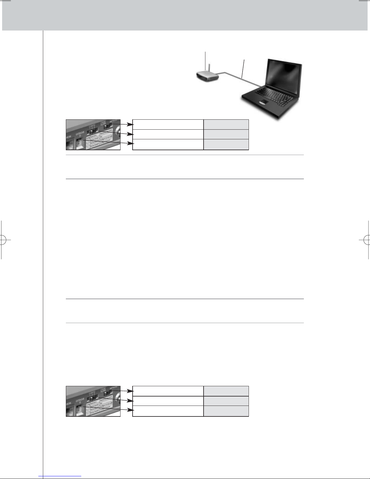
To configure the Network Extender:
1Connect the Extender to the PC with the
configuration cable (this is the crossed
Ethernet cable enclosed).
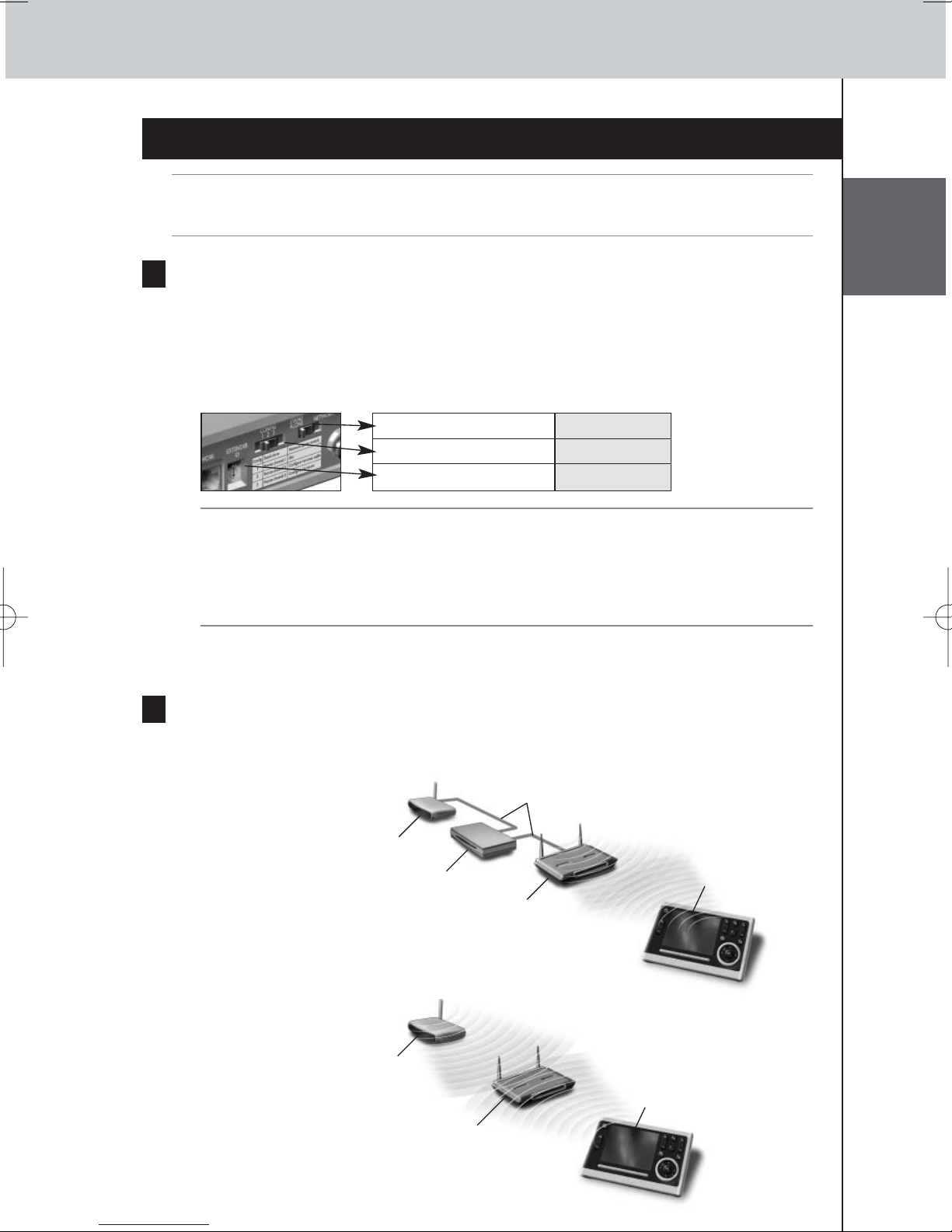
2Set the switches correctly:
Note •If there is already an Extender with ID 0, set the Extender ID switch to an ID that is not
used yet.
•Make sure the same Extender ID is used on the Extender and the Pronto Control Panel.
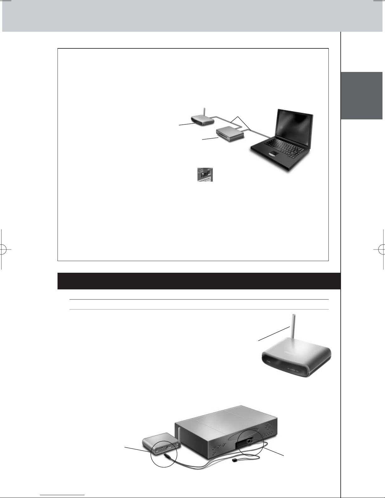
3Plug in the Extender’s power adapter.
The Extender will start up. After startup, the Power and Ethernet LEDs are green and the Busy
LED is red/green blinking.
4Open the browser.
5Type the IP address of the Extender (printed on the bottom of the Extender) in the
address bar of the browser.
The Configuration Tool opens in the browser.
6Follow the onscreen instructions and make sure you have the following information at
hand:
•If the Extender will be connected wirelessly to the Pronto Network: the SSID and
encryption settings.
•If the Extender will be operating with a fixed IP address: the IP address, netmask and
default gateway.
Tip To ensure optimal performance, use a dedicated network for all Pronto communication.
This makes the Pronto Network independent from other network traffic and changes in
network settings.
7Disconnect the Extender from the PC.
8Connect the Extender to the Pronto Network:
•For a wired connection, connect the Extender to the router by means of a straight Ethernet
cable.
•For a wireless connection, you do not need to connect any more cables.
9Set the switches correctly:
The Extender will restart. After startup,
•In a wired network connection, the Power and Ethernet LEDs are green and the Busy LED
blinks green when it’s processing a code or a macro from the Control Panel.
•In a wireless network connection, the Power and WiFi LEDs are green and the Busy LED
blinks green when it’s processing a code or a macro from the Control Panel.
Extender Configuration
cable
Stand-alone/Network Network
Configuration switch 2
Extender ID 0
Stand-alone/Network Network
Configuration switch 1
Extender ID 0
RFX9400_SG_ESF_v06.qxd 04-07-2006 08:12 Pagina 8

ENGLISH
6
RFX9400 Starter’s Guide
Configuring the Extender through a Router
When the Extender is already installed and connected to external AV-equipment, it is possible to
configure it through a router.
1Connect the Extender to the router, and the router to the PC, as indicated below.
2Set the Extender’s Configuration switch to 3.
3Open the ProntoEdit Professional on the PC.
4In the Tools menu, select Extender Discovery.
The Extender Discovery tool appears, with a list of all the detected Extenders in the Pronto
Network.
5Select the Extender that you want to configure and click on the Configure button.
The Configuration Tool opens in the browser.
6Finalize the configuration, as described in the instructions on page 5.
Installing the Extender
Warning Keep the Extender away from heat sources such as amplifiers.
Before connecting the Extender to external AV-equipment,
make sure that the antenna is placed correctly.
Connecting the Extender to AV-equipment
To connect the Extender to AV-equipment, use one of the following cables enclosed with the
Extender:
•aDual IR emitter;
Place the antenna
in an upright
position.
Extender
Straight
Ethernet cable
Router
Insert the mini-jack
connector of the
Dual IR emitter in
the IR output of
the Extender.
Attach the
emitter to the
infrared receiver
of the AV-
component.
RFX9400_SG_ESF_v06.qxd 04-07-2006 08:12 Pagina 9

7
RFX9400 Starter’s Guide
LEDs
Colors Ethernet LED WiFi LED Busy LED
The Extender’s IP address is
being determined.
Green blinking The Extender’s IP address is
being determined.
The Extender is busy processing
a short code or macro from the
Control Panel.
The Extender is functioning
normally.
Green The Extender is functioning
normally.
The Extender is busy processing
a long macro from the Control
Panel.
–
Red/green blinking –The Extender is being
configured.
Refer to the topic ‘There is an
IP conflict’ on page 7.
Red Refer to the topic
‘The Extender cannot
communicate with the
wireless network’ on page 8.
Refer to the topic ‘There are
duplicate Extender IDs’
on page 8.
Refer to the topic ‘The IP address
cannot be determined’ on
page 7.
Red blinking The Extender is starting up.
Wait until startup has finished.
-or-
•amini-jack IR cable.
Adjusting the Power Level of the IR Outputs
At the back of the Extender, there are 4 dipswitches, one for each IR output. Use these dipswitches
to configure the power level of the Dual IR emitters and the mini-jack cables.
For example, flip the dipswitch down to lower the power level when the Extender is connected to
an external IR bus system.
Support
Troubleshooting
What Do the LEDs Indicate?
Insert one mini-jack
connector of the
mini-jack cable in
the IR output of the
Extender.
Insert the other
mini-jack
connector in the
AV-component.
There is an IP conflict
There is another AV-component in the network that is using the same fixed IP address as the
Extender. Change the IP address of the Extender in the Configuration Tool.
If the problem persists, check the router settings.
The IP address cannot be determined
•When using the Extender: make sure that the Extender is connected to the router with a straight
Ethernet cable.
RFX9400_SG_ESF_v06.qxd 04-07-2006 08:12 Pagina 10

ENGLISH
8
RFX9400 Starter’s Guide
•When configuring the Extender: make sure the PC is not using a fixed IP address but is using
DHCP instead.
•Make sure the router is switched on. If the router is using DHCP, the Extender’s IP address cannot
be determined. Make sure to use the correct network settings on the router.
The Extender cannot communicate with the wireless network
The WiFi LED is red
•Make sure that the Extender is in range of the Wireless Access Point.
•Make sure that you filled in the correct secret in the Configuration Tool.
•Add the Extender’s MAC address to the router’s list of accepted MAC addresses.
The WiFi LED is red blinking
•Check the router’s network settings and make sure that it can operate with the Extender.
•If the LED doesn’t stop blinking, unplug the power adapter, wait a few seconds, and plug it in
again.
Finding the Exact Location of an AV-component’s IR Receiver
1Remove the protective tape of the Dual IR emitters.
2Set the Dual IR emitters to the minimal power level, and hold the adhesive side of one
of the emitters 0.4 - 0.8 inch / 1 - 2 cm in front of the AV-component.
3Make sure the Control Panel is configured to operate with the AV-component.
4Move the emitter across the front panel of the AV-component, and at the same time,
send commands with the Control Panel to the AV-component.
Take note of when the AV-component reacts to the IR signals of the emitter.
5When the AV-component reacts, position the emitter in that place.
Operating AV-components with the Extender
The AV-components do not respond to commands from the Extender
•Check if the Busy LED blinks green when you send a command with the Control Panel. If the Busy
LED does not blink, the Extender is not receiving commands from the Control Panel;
•Make sure that the Control Panel is configured correctly in ProntoEdit Professional;
•Make sure that the Extender is configured correctly in the Configuration Tool and connected
properly to the AV-components;
•Make sure that the switches on the Extender are set correctly.
•Make sure that the Wireless Access Point is on and configured correctly.
•Make sure that the Extender is in range of the Wireless Access Point. If the Wireless Access
Point is placed higher or lower than the Extender, place the Extender’s antenna horizontally for
optimum range.
There are duplicate Extender IDs
Using the Extender ID switch, assign a unique ID to each Extender in the same Pronto Network.
Make sure the Control Panel is configured accordingly in ProntoEdit Professional.
You can use up to 16 different Extenders in the same Pronto Network.
RFX9400_SG_ESF_v06.qxd 04-07-2006 08:12 Pagina 11

9
RFX9400 Starter’s Guide
The Busy LED blinks green when the Control Panel is not in use
This does not mean that something is wrong with the Extender. It merely indicates that the Extender
is being operated by a different Control Panel. When the Busy LED stops blinking, you can use the
Extender again.
Resetting the Extender
This is only necessary when the Extender displays unusual behavior.
To perform a reset, unplug the Extender from the electrical socket. Wait a few seconds, and plug it
in again.
Firmware Update
When an update of the Extender firmware is available, this will be announced on the Philips Pronto
website: www.pronto.philips.com.
Note You can always see the current version of the firmware in the Configuration Tool.
1Download the new version of the firmware on the PC.
2Unplug the Extender. The Extender can be updated in the following ways.
Updating the Extender with the configuration cable
1Connect the Extender to the PC with the configuration cable.
2Set the switches correctly.
3 Open the browser.
4Type the IP address of the Extender (printed on the bottom of the Extender) in the
address bar of the browser.
The Configuration Tool opens in the browser.
5Select Firmware Update in the left navigation pane.
The Firmware Update page opens.
6Follow the onscreen instructions.
Updating the Extender through a router
If the Extender is already installed and connected to AV-equipment, it may be more convenient to
update it through a router.
1 Connect the Extender to the router, and the router to the PC.
2 Set the switches correctly.
Stand-alone/Network Network
Configuration switch 2
Extender ID 0
Stand-alone/Network Network
Configuration switch 3
Extender ID 0
RFX9400_SG_ESF_v06.qxd 04-07-2006 08:12 Pagina 12

ENGLISH
10
RFX9400 Starter’s Guide
3Open the ProntoEdit Professional on the PC.
4In the Tools menu, select Extender Discovery.
The Extender Discovery tool appears, with a list of all the detected Extenders in the Pronto
Network.
5Select the Extender that you want to configure and click on the Configure button.
The Configuration Tool opens in the browser.
6Select Firmware Update in the left navigation pane.
The Firmware Update page opens.
7 Follow the onscreen instructions.
Specifications
The specifications and design of this product are subject to change without notice.
General Dark grey ABS housing with poly carbonate front plate
802.11 b/g compliant RF technology
4 LED indications for Power, WiFi, Network and Busy
Up to 16 extenders and 16 control panels in a system (for all modes)
4 addressable outputs for IR emitters
Ethernet RJ45 connection
Rotatable RF antenna
Positioning: freestanding or mounted in any position
Modes Stand-alone (wireless): Similar to WiFi ad-hoc mode; no access point and
router required
Network (wireless): Similar to WiFi infrastructure mode; used in a system with
a router and access point
Network (wired via Ethernet): used in a system with a router and access point
Dimensions 3,98 x 6,18 x 1,3 inch (101,2 x 157 x 33,5 mm)
Operating temperature 32°F to 122°F (0°C to 50°C)
Infrared (IR) IR frequency range: 25kHz-1MHz (including DC/flash codes)
IR power out: 2 levels
Radio Frequency (RF) 802.11g at 2.4 GHz with additional proprietary protocol
Dual IR emitters Number of IR emitters: up to 4 (2x2), emitters wired in series
0.13 inch (3.5 mm) mono mini-jack
Cable length: 9 ft (2.7 meters)
Mono mini-jack cables 0.13 inch (3.5 mm) mono mini-jack
Cable length: 5 ft (1.5 meters)
Power adapter 100V-240 VAC / 50-60 Hz Power adapter (5V DC/2A output, UL-CE approved)
Pronto Wireless Extender Starter’s Guide
© Copyright 2006 Royal Philips Electronics, Interleuvenlaan 72 - 74, 3000 Leuven (Belgium)
Remarks:
All rights are reserved. Reproduction in whole or in part is prohibited without prior consent of the copyright owner.
Royal Philips Electronics is not liable for omissions or for technical or editorial errors in this manual or for damages
directly or indirectly resulting from the use of the Pronto Wireless Extender.
The information in this Starter’s Guide may be subject to change without prior notice.
All brand or product names are trademarks or registered trademarks of their respective companies or organizations.
RFX9400_SG_ESF_v06.qxd 04-07-2006 08:12 Pagina 13

1
RFX9400 Manual de inicio
Contenido
Antes de empezar ...........................................2
Contenido del paquete del Extensor...................3
Configuración del Extensor...............................4
Conexión Stand-alone..................................4
Conexión Network ......................................4
Instalación del Extensor ...................................6
Conexión del Extensor a un equipo AV .............6
Asistencia ......................................................7
Detección de errores ...................................7
Actualización de Firmware ............................9
Especificaciones ...........................................10
IFU Approbation / Safety Content RFX9400...........i
FCC Compliancy ..........................................i
Regulations According to R&TTE.....................ii
Modo Stand-alone
(modo autónomo)
Modo Network
(modo red)
RFX9400_SG_ESF_v06.qxd 04-07-2006 08:12 Pagina 14

ESPAÑOL
2
RFX9400 Manual de inicio
Antes de empezar
El Pronto Wireless Extender es un elemento importante del Sistema Pronto y permite controlar
equipos AV mediante RF en toda la casa.
Para utilizar el Extensor en una red Pronto inalámbrica:
•Configure el Extensor: conéctelo al PC y utilice la herramienta de configuración Configuration
Tool.
•Instale el Extensor: conéctelo a un equipo AV externo, como un televisor o un receptor.
El Extensor puede utilizarse en dos modalidades:
Modo Stand-alone (modo autónomo)
Esta modalidad también se conoce como “modo Ad-Hoc”: no se requiere router.
Ventajas del modo Stand-alone:
•El Extensor se instala y se configura fácilmente.
•Funciona independientemente de otras redes o configuraciones de red.
Consulte el capítulo ‘Conexión Stand-alone’ en la página 4 para configurar el Extensor en modo
Stand-alone.
Nota Si desea utilizar el servidor de audio Escient Fireball en combinación con uno o más Extensores,
los Extensores deben estar configurados en modo Network.
Modo Network (modo red)
Esta modalidad también se conoce como “modo Infraestructura”: el Extensor se utiliza en una red
con un router.
Ventajas del modo Network:
•Una red permite el uso de repetidores, lo que aumenta el radio de alcance del Sistema Pronto.
•Cuando se utiliza una red Pronto dedicada, el Extensor puede funcionar independientemente de
las configuraciones de otras redes.
•Se puede asignar una dirección IP fija al Extensor en modo Network, lo que aumenta la fiabilidad.
•La conexión de red se puede cifrar.
Consulte el capítulo ‘Conexión Network’ en la página 4 para configurar el Extensor en modo Network.
Nota Un Extensor configurado en modo Stand-alone puede reconfigurarse para uso en modo
Network, y viceversa.
Puede utilizar hasta 16 Extensores diferentes en la misma red Pronto.
RFX9400_SG_ESF_v06.qxd 04-07-2006 08:12 Pagina 15

RFX9400 Manual de inicio
3
Contenido del paquete del Extensor
Pronto Wireless Extender
Panel frontal
Antena
Interruptor de
Configuración
•En modo Stand-alone:
cambia el canal RF.
•En modo Network:
indica el tipo de
conexión.
Entrada de
corriente
4 salidas IR
4 conmutadores DIP
para las salidas IR
Panel trasero
Interruptor del ID
del Extensor
Entrada Ethernet
(RJ45)
Interruptor
Stand-alone/ Network
2 emisores IR duales 2 cables IR con
conectores mini-jack
Adaptador de
corriente
Cable de configuración
Cable Ethernet cruzado
Indicador LED WiFi
Indicador LED Ethernet
Indicador LED Busy (ocupado)
Indicador
LED Power
(encendido)
RFX9400_SG_ESF_v06.qxd 04-07-2006 08:12 Pagina 16

RFX9400 Manual de inicio
ESPAÑOL
4
Configuración del Extensor
Nota Antes de empezar a configurar el Extensor, compruebe si hay alguna actualización de firmware
disponible en la sección de Downloads de www.pronto.philips.com.
Consulte el capítulo ‘Actualización de Firmware’ en la página 9 para obtener más información
al respecto.
Conexión Stand-alone
Para configurar el Extensor Stand-alone:
1 Conecte el adaptador de corriente del Extensor.
El Extensor arrancará. Cuando finalice el proceso de arranque, los indicadores LED Power y
WiFi estarán iluminados en verde.
2Utilice la configuración de los interruptores por omisión del Extensor:
Nota •Si ya existe un Extensor con el ID 0, ajuste el interruptor del ID del Extensor a un ID que
no esté en uso.
•Si hay alguna interferencia con otros productos dentro o cerca de la casa, se puede
ajustar el interruptor de Configuración a un canal RF distinto.
•Asegúrese de que utiliza el mismo ID del Extensor y canal RF en el Extensor y en el
Control Panel de Pronto.
3Configure el archivo de configuración del Control Panel (el Panel de Control) para que
el Control Panel pueda trabajar con el Extensor. Para más información, consulte la
ayuda ProntoEdit Professional Online Help.
Conexión Network
En el caso de una conexión de red, el Extensor forma parte de la red Pronto inalámbrica. Hay dos
maneras de utilizar el Extensor en una red:
•Conexión con cable
•Conexión inalámbrica
Extensor
Router
Punto de
acceso inalámbrico
Cable Ethernet directo
Extensor
Punto de
acceso inalámbrico
Control Panel
Control Panel
Stand-alone/Network Stand-alone
Interruptor de Configuración 1
ID del Extensor 0
RFX9400_SG_ESF_v06.qxd 04-07-2006 08:12 Pagina 17

RFX9400 Manual de inicio
5
Para configurar el Extensor Network:
1Conecte el Extensor al PC con el cable de
configuración (el cable Ethernet cruzado
incluido).
2Ajuste los interruptores correctamente:
Nota •Si ya existe un Extensor con el ID 0, ajuste el interruptor del ID del Extensor a un ID que
no esté en uso.
•Asegúrese de que utiliza el mismo ID del Extensor en el Extensor y en el Control Panel
de Pronto.
3Conecte el adaptador de corriente del Extensor.
El Extensor arrancará. Después de arrancar, los indicadores LED Power y Ethernet estarán
iluminados en verde, y el indicador LED Busy parpadeará en rojo/verde.
4Abra el navegador.
5 Escriba la dirección IP del Extensor (impresa en la parte inferior del Extensor) en la
barra de direcciones del navegador.
La herramienta Configuration Tool se abrirá en el navegador.
6Siga las instrucciones que aparecen en pantalla y asegúrese de que tiene la siguiente
información a mano:
•Si el Extensor va a conectarse de forma inalámbrica a la red Pronto: la configuración de
cifrado y SSID.
•Si el Extensor va a funcionar con una dirección IP fija: la dirección IP, la máscara de red
y la puerta de enlace predeterminada.
Consejo Para garantizar un rendimiento óptimo, utilice una red dedicada para todas las
comunicaciones Pronto. De este modo, la red Pronto se hace independiente de otros
tráficos de red y de cambios en las configuraciones de red.
7Desconecte el Extensor del PC.
8Conecte el Extensor a la red Pronto:
•Para una conexión por cable, conecte el Extensor al router utilizando un cable Ethernet directo.
•Para una conexión inalámbrica, no necesita conectar ningún otro cable.
9Ajuste los interruptores correctamente:
El Extensor se reiniciará. Cuando haya arrancado,
•En una conexión de red por cable, los indicadores LED Power y Ethernet estarán iluminados
en verde, y el indicador LED Busy parpadeará en verde cuando se procese un código o una
macro desde el Control Panel.
•En una conexión de red inalámbrica, los indicadores LED Power y WiFi estarán iluminados
en verde, y el indicador LED Busy parpadeará en verde cuando se procese un código o una
macro desde el Control Panel.
Extensor
Cable de configuración
Stand-alone/Network Network
Interruptor de Configuración 2
ID del Extensor 0
Stand-alone/Network Network
Interruptor de Configuración 1
ID del Extensor 0
RFX9400_SG_ESF_v06.qxd 04-07-2006 08:12 Pagina 18

RFX9400 Manual de inicio
ESPAÑOL
6
Configuración del Extensor a través de un router
Cuando el Extensor está instalado y conectado a un equipo AV externo, es posible configurarlo a
través de un router.
1Conecte el Extensor al router, y el router al PC, tal como se indica a continuación.
2Ajuste el interruptor de Configuración del Extensor a la posición 3.
3Abra ProntoEdit Professional en el PC.
4 En el menú Tools, seleccione Extender Discovery.
La herramienta Extender Discovery aparecerá, con una lista de todos los Extensores detectados
en la red Pronto.
5Seleccione el Extensor que quiera configurar y pulse el botón Configure.
La herramienta Configuration Tool se abrirá en el navegador.
6Finalice la configuración, tal como se describe en las instrucciones de la página 5.
Instalación del Extensor
Advertencia Mantenga el Extensor lejos de fuentes de calor como, por ejemplo, amplificadores.
Antes de conectar el Extensor a un equipo AV externo,
asegúrese de que ha colocado la antena correctamente.
Conexión del Extensor a un equipo AV
Para conectar el Extensor a un equipo AV, utilice uno de los siguientes cables incluidos con el
Extensor:
•un emisor IR dual;
Coloque la
antena en
posición vertical.
Extensor
Cable Ethernet directo
Router
Introduzca el
conector mini-jack
del emisor IR dual
en la salida IR del
Extensor.
Conecte el
emisor al
receptor de
infrarrojos del
componente AV.
RFX9400_SG_ESF_v06.qxd 04-07-2006 08:12 Pagina 19

RFX9400 Manual de inicio
7
Ind. LED
Colores Indicador LED Ethernet Indicador LED WiFi Indicador LED Busy
Se está determinando la
dirección IP del Extensor.
Parpadeo verde Se está determinando la
dirección IP del Extensor
El Extensor está ocupado
procesando una macro o un código
corto desde el Control Panel.
El Extensor está funcionando con
normalidad.
Verde El Extensor está funcionando
con normalidad
El Extensor está ocupado
procesando una macro larga desde
el Control Panel.
–
Parpadeo rojo/verde –Se está configurando el Extensor.
Consulte el tema ‘Hay un
conflicto de IP’ en la página 7.
Rojo Consulte el tema ‘El Extensor
no puede establecer
comunicación con la red
inalámbrica’ en la página 8.
Consulte el tema ‘Hay ID del
Extensor duplicados’ en la página 8.
Consulte el tema ‘La dirección IP
no puede determinarse’ en la
página 7.
Parpadeo rojo El Extensor está arrancando. Espere
hasta que termine de arrancar.
-o-
•un cable IR con conectores mini-jack.
Ajuste del nivel de corriente de las salidas IR
En la parte trasera del Extensor, hay 4 conmutadores DIP, uno para cada salida IR. Utilice estos
conmutadores DIP para configurar el nivel de corriente de los emisores IR duales y los cables con
conectores mini-jack.
Por ejemplo, gire el conmutador DIP hacia abajo para bajar el nivel de corriente cuando el Extensor
esté conectado a un sistema bus IR externo.
Asistencia
Detección de errores
¿Qué indican los indicadores LED?
Introduzca un
conector del cable
con conectores
mini-jack en la
salida IR del
Extensor.
Introduzca el
otro conector en
el componente
AV.
Hay un conflicto de IP
Hay otro componente AV en la red que está utilizando la misma dirección IP fija que el Extensor.
Cambie la dirección IP del Extensor en la herramienta Configuration Tool.
Si el problema persiste, compruebe la configuración del router.
La dirección IP no puede determinarse
•Al utilizar el Extensor: asegúrese de que el Extensor esté conectado al router con un cable
Ethernet directo.
RFX9400_SG_ESF_v06.qxd 04-07-2006 08:12 Pagina 20
Other manuals for Pronto RFX9400
1
This manual suits for next models
5
Table of contents
Languages:
Other Philips Network Router manuals

Philips
Philips SNB6500/00 User manual

Philips
Philips CGA7740N/05 User manual

Philips
Philips CGA7740N User manual

Philips
Philips SNB5600/00 User manual

Philips
Philips dynalite DDPB22RJ12 User manual

Philips
Philips CKW7740N/00 User manual

Philips
Philips SNB6500 User manual

Philips
Philips CKW7740N User manual

Philips
Philips Fidelio AW1000 User manual

Philips
Philips SNA6500/05 User manual