MITS Design Pro CAM-T User manual

M
MI
IT
TS
S
D
De
es
si
ig
gn
n
P
Pr
ro
o
.
.
C
CA
AM
M-
-T
T
f
fo
or
r
F
FP
P-
-2
21
1T
T

1
・Precautions
◆Intended Use
The intended use of the PCB Prototyping Machine is to process PCB by milling,
drilling and routing. Any other uses are strongly prohibited.
◆While Processing
Keep away from the machine especially the spindle head while processing.
Spindle head is constantly moving. Be sure to keep away and not to get your
caught in the machine. Make sure to wear eye protective gear/goggle while
processing.
◆Power Voltage
The allowable voltage for FP-21T is 85V~264V.If the voltage of your
region is out of range, be sure to use voltage regulator.
◆Working Area
The working area of FP-21T is 350mm x 250mm. Be sure to process within the
working area of Auto Lab.
◆Dry Run and Milling Speed
Below is the optimal speed for Auto Lab.
Dry Run ‥‥ 20~30mm/sec
Milling Speed ‥‥ 12~18mm/sec
Routing Speed ‥‥ 1~2mm/sec
If the processing speed is too fast during processing or manual operation,
step-out could occur to the machine.
◆Milling/Drill/Routing Tool Settings
The machine will process with the settings in CAM Pref.→Milling ・Drill ・
Routing. If the parameter in the setting is missing or unintended value, there
is a possibility of tools breaking or processing error occurring. Be sure
to check the parameter in the settings.
◆Vacuum Cleaner
While processing, if the dust from the PCB piles up, not only the processing
quality is affected by it, there also is a chance of spindle motor
malfunction. Be sure to use Vacuum Cleaner while processing.

2
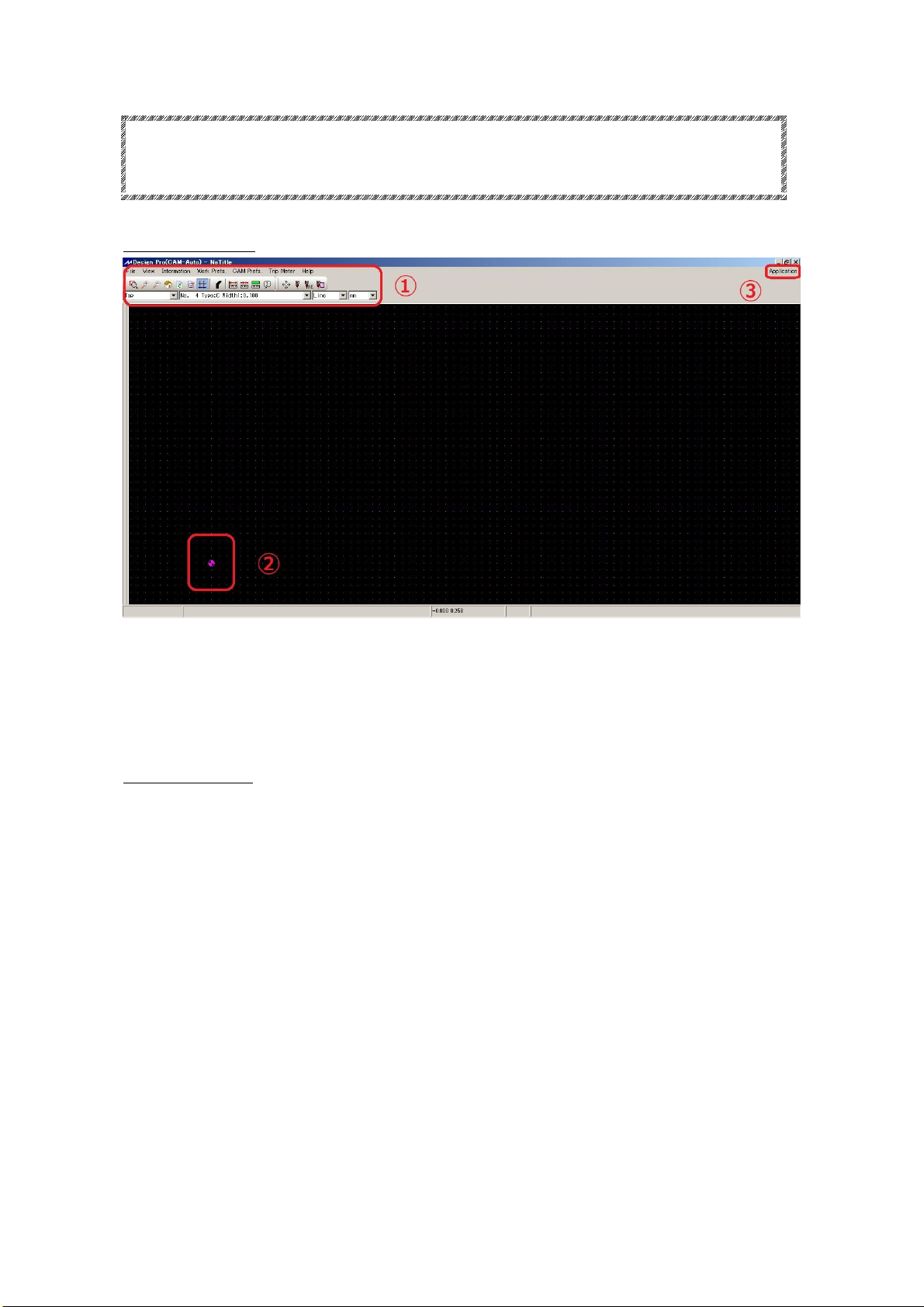
◆CAD with Dongle Key
Make sure to remove Dongle key when you are using the prototyping machine.
Connection error may occur and prototyping machine may be unable to use.
◆Tools and RPM
For processing, set the RPM to 30~40. The unit in the software is x 1000RPM.
To drill 0.3~0.4mm size holes, set the Lower2 3~4mm/sec.
IMPORTANT
To drill 0.3~0.4mm size holes, go to CAM Pref. →Board Maker and set
the Lower2 3~4mm/sec. After setting the Lower2 speed slower, make sure
to set Drill Wait and Before Cutting longer than the default setting. If
not, there is a possibility of spindle head moving too early before the
drilling is completely penetrated.
◆Transportation
Since the Auto Lab precision machine, use the container box which was used
for shipping. For long distant transportation using carrier, make sure to
select carrier with great handle care with the transportation.
Do not apply any force to the shaft, lead screw, spindle head while
transportation. It could result to have the accuracy to drop.
◆Spindle Motor Cleaning
Note that spindle motor and collet are ultra-precision component. In order
to keep the machine performance well, daily checkup and cleaning is necessary.
Spindle motor may result to malfunction when dust or debris are caught between
tool and collet, decreasing the holding power of the tools. Make sure to check
and clean the spindle motor before using.
◆Warranty
The term of warranty for PCB Prototyping Machine is 1 year with the intended
use. Note that spindle motor and consumable supplies are not included in the
warranty. Also note that even within the warranty period, below circumstances
will be considered as charged repair. Improper use, inappropriate assembly,
damage/breakage by carelessness, natural disaster, abrasion, modification,
use of non-genuine components/parts, use in undesignated voltage. Please
operate with great care when you are using the machine without any training.

3
Contents
・Introduction ・・・・・・・・・・・・・・・・・・・・・・・・・・・・・・ P.4
・Prototyping Machine Part Name ・・・・・・・・・・・・・・・・・・・・・ P.5
・CAM-Auto Screen Basic Operation ・・・・・・・・・・・・・・・・・・・・ P.7
・Setup Operation Check ・・・・・・・・・・・・・・・・・・・・・・・・・P.8
Ⅰ. Procedures ・・・・・・・・・・・・・・・・・・・・・・・・・・・・・・・ P.10
Ⅱ. Preparation ・・・・・・・・・・・・・・・・・・・・・・・・・・・・・・P.11
Ⅲ. Set Milling Sequences ・・・・・・・・・・・・・・・・・・・・・・・・・P.14
Ⅳ. Adjust ・・・・・・・・・・・・・・・・・・・・・・・・・・・・・・・・・ P.17
Ⅴ. Process Top Layer ・・・・・・・・・・・・・・・・・・・・・・・・・・・ P.30
Ⅵ. Adjust/Align Bottom Layer ・・・・・・・・・・・・・・・・・・・・・・・ P.34
Ⅶ. Process Bottom Layer ・・・・・・・・・・・・・・・・・・・・・・・・・・ P.39
Ⅷ.After Completed ・・・・・・・・・・・・・・・・・・・・・・・・・・・・P.43
・Trouble Shooting (USB,RS232C Serial Connection) ・・・・・・・・・・・・ P.44
・Trouble Shooting (Prototyping Machine) ・・・・・・・・・・・・・・・・・ P.46

4
・Introduction
This manual is a tutorial guide to prototype PCB with Design Pro CAM-T.
For further explanation, “mdemo.mit”file is used, which is automatically saved
on to your computer when the software is installed.
Below are the board and the tools used in this tutorial guide.
Board
-Double-Sided Copper Cladded
-Thickness: 1.6mm
-Copper Thickness: 35μm
Tools
-90°Milling Bit 36mm
-Drill Bit 0.8mm 38mm
-Router Bit 1.0mm 38mm
<File Used>mdemo.mit

5
・Prototyping Machine Part Name
1–Power Switch
2–Spindle Head
3–Working Table
4–Pressure Foot
5–Depth Adjustment Screw
6–USB Camera
7–Tool Change Lever
8–Vacuum Nozzle

6
9–Fuse Holder
10 –AC IN (Power Plug)
11 –AC OUT (Vacuum Outlet)
12 –RS-232C Port
13 –USB Port

7
・CAM-Lab Screen Basic Operation
CAM-Lab Screen
①-Command Icons
②-CAD Origin
③-Application
Basic Operation
Mouse
Scroll:Move Up/Down
Shift + Scroll:Move Right/Left
Ctrl + Scroll:Zoom In/Out
Keyboard
Esc:Pause Milling
Backspace:Undo
Shift + Backspace:Redo
Delete:Delete Selected Element

8
・Setup Operation Check
1.Connect the power cable to the AC In (Power Plug).
2.Attach and hold the vacuum hose by fixing the plastic vacuum holder on the
backside of the machine with the screw.
3.Attach vacuum hose into the connector.

9
4.Connect the USB cable to the USB port.
5.Connect the Vacuum Cleaner to the Prototyping Machine with power cable. Be
sure to turn the Vacuum Cleaner power “On”at all time.
6.Turn the power switch “On”. The spindle head will move to the back left
corner.
→
Warning: Please contact us if the machine does not move to the back left corner.

10
Ⅰ.Procedures
The below is the procedures to produce prototype PCB.
Preparation
-Open “mdemo.mit”file
-Setup underlay and PCB
↓
Set Milling Sequence
↓
Adjust
-Set P1P2
-Camera Offset
-Adjust Milling Width
-Drill Fiducial Holes
↓
Process Top Layer
-Drill (Top)
-Mill (Top)
↓
Adjust Bottom
↓
Process Bottom Layer
-Mill (Btm)
-Route (Btm)

11
Ⅱ.Preparation
First you will begin with the below steps.
1 -Open mdemo.mit file(1~2)
2 -Set underlay and PCB on working table(3~4)
mdemo.mit file (below)
After setup (below)

12
1. Click on Application and select CAM-T
2. Go to File →Open and select mdemo.mit file. The files are saved as below
for each OS.
Windows 7:
Document →Public Document →Mits Software →MT Path →Data →
mdemo.mit
Windows Vista:
Public →Documents →Mits Software →MT Path →Data →mdemo.mit
Windows XP:
Local Disc(C:)→Documents and Settings →All Users →Shared Document
→Mits Software →MT Path →Data →mdemo.mit

13
3. Next you will set underlay and PCB on to the working table.
Clear the working table and place the underlay.
Use the masking tape to hold the underlay.
4. Clear the underlay and place the PCB.
Use the masking tape to hold the PCB.
You’ve completed the underlay and PCB setup. Now you will proceed to Set Milling
Sequences.

14
Ⅲ.Set Milling Sequences
Now you will set Milling Sequence. The sequence is as below.
-Drill (Top)
-Mill (Top)
-Mill (Btm)
-Routing (Btm)

15
1.Click on Start Job Icon
2.Window shown below will appear. Click Yes(Y).
3.Milling Sequence Settings window will appear.
Check and see X quantity and Y quantity is set to 1.
4.Next you will move the jobs from Milling Job List to Milling Sequence List.
Double click on Drill (Top) in Milling Job List. The job will move to the
Milling Sequence List.
→

16
5. Repeat the above and move the below jobs to the Milling Sequence List.
-Mill (Top)
-Mill (Btm)
-Routing (Btm)
6. Click OK and the machine will move.
Now Milling Sequence setting is completed.

17
Ⅳ.Adjust
In Adjust you will do the below steps.
1 -Set P1 P2 (2~5)
2 -Set Camera Offset (6~14)
3 -Set Milling Width (15~17)
4 -Drill Fiducial Holes (18~25)
P1 P2:P1 P2 are the points used to determine the actual working area during the
prototyping. As shown in the picture below, P1 is the intersected point which
is 2mm to the left and down from the working area P2 is 2mm right and up from
the working area. You will set P1 and P2 is automatically calculated and
derived.

18
1. Board Top/Bottom Change window will appear
Click Adjust and Manual Operation Window will appear
Now you will set P1 and P2.
2. Move the machine to the front left corner by using the Movement Icon (FRONT,
BACK, LEFT, RIGHT) and entering distance to move per click in Move Distance.
3. After moving the head to the left corner, click Set P1-P2.
4. Confirm P2 window will appear. Click No(N).

19
5. Click P1 and P2 button to check if the spindle head stays inside the PCB.
WARNING:Do not set P1 all the way at the left corner. Camera will not be
able to use to read the fiducial hole when the board is flipped over.
P1 P2
P1 P2 setting is completed. Now you will set Camera Offset.
6. First, click P1 button.
Table of contents
Other MITS Industrial Equipment manuals
Popular Industrial Equipment manuals by other brands

MULTIQUIP
MULTIQUIP Whiteman series Operation and parts manual

ABB
ABB HT604384 Operation manual

DOGA
DOGA SLIDER Series user manual

Zimmer
Zimmer DKHS1000 Series Installation and operating instructions

ABB
ABB HT611114 Operation manual

Speedline Technologies
Speedline Technologies ELECTROVERT Aquastorm Options guide