AUMA GSTI 25.1 User manual
Multi-turn gearboxes
GSTI 25.1 –GSTI 40.1
for use in nuclear power plants
(Inside/Outside Containment)
Assembly and commissioningOperation instructions

Read operation instructions first.
●Observe safety instructions.
●These operation instructions are part of the product.
●Store operation instructions during product life.
●Pass on instructions to any subsequent user or owner of the product.
Target group:
This document contains information for assembly, commissioning and maintenance staff.
Table of contents Page
31. Safety instructions................................................................................................................. 31.1. Basic information on safety 31.2. Range of application 41.3. Warnings and notes 41.4. References and symbols
52. Short description...................................................................................................................
63. Name plate..............................................................................................................................
84. Transport and storage........................................................................................................... 84.1. Transport 94.2. Storage
115. Assembly................................................................................................................................ 115.1. Mounting position 115.2. Handwheel fitting 115.3. Multi-turn actuators for motor operation 135.4. Mount gearbox to valve 135.4.1. Overview of output drive types 135.4.2. Output drive type A 145.4.2.1. Mount gearbox with output drive type A to valve 145.4.2.2. Finish machining of stem nut for output drive type A 155.4.3. Output drive types B/C 165.4.3.1. Mount gearbox with output drive types B to valve 175.5. Accessories for assembly 175.5.1. Stem protection tube for rising valve stem
186. Commissioning...................................................................................................................... 186.1. Seating via multi-turn actuator
197. Servicing and maintenance................................................................................................... 197.1. Preventive measures for servicing and safe operation 197.2. Maintenance intervals 197.3. Disposal and recycling
218. Technical data......................................................................................................................... 218.1. Technical data Multi-turn gearboxes
229. Spare parts............................................................................................................................. 229.1. Multi-turn gearboxes GSTI 25.1 –GSTI 40.1
26Index........................................................................................................................................
2
GSTI 25.1 –GSTI 40.1 for use in nuclear power plants
Table of contents (Inside/Outside Containment)

1. Safety instructions
1.1. Basic information on safety
Standards/directives Our products are designed and manufactured in compliance with recognised
standards and directives.This is certified in a Declaration of Incorporation and an
EU Declaration of Conformity.
The end user or the contractor must ensure that all legal requirements, directives,
guidelines, national regulations and recommendations with respect to assembly,
electrical connection, commissioning and operation are met at the place of installation.
They include among others standards, directives and regulations on radiation
protection in nuclear power plants.
Safetyinstructions/warn-
ings All personnel working with this device must be familiar with the safety and warning
instructions in this manual and observe the instructions given. Safety instructions
and warning signs on the device must be observed to avoid personal injury or property
damage.
Qualification of staff Assembly, electrical connection, commissioning, operation, and maintenance must
be carried out exclusively by suitably qualified personnel having been authorised by
the end user or contractor of the plant only.
Prior to working on this product, the staff must have thoroughly read and understood
these instructions and, furthermore, know and observe officially recognised rules
regarding occupational health and safety.
Work performed in radiation exposed areas is subject to special regulations which
have to be observed.The end user or contractor of the plant are responsible for
respect and control of these regulations, standards, and laws.
Commissioning Prior to commissioning, it is important to check that all settings meet the requirements
of the application. Incorrect settings might present a danger to the application, e.g.
cause damage to the valve or the installation.The manufacturer will not be held
liable for any consequential damage. Such risk lies entirely with the user.
Operation Prerequisites for safe and smooth operation:
●Correct transport, proper storage, mounting and installation, as well as careful
commissioning.
●Only operate the device if it is in perfect condition while observing these instruc-
tions.
●Immediately report any faults and damage and allow for corrective measures.
●Observe recognised rules for occupational health and safety.
●Observe the national regulations.
●During operation,the device warms upand increasedsurface temperature may
occur.To prevent possible burns, we recommend checking the surface temper-
ature using an appropriate thermometer and wearing protective gloves, if re-
quired, prior to working on the device.
Protective measures The end user or the contractor are responsible for implementing required protective
measures on site, such as enclosures, barriers, or personal protective equipment
for the staff.
Maintenance To ensure safe device operation, the maintenance instructions included in this manual
must be observed.
Any device modification requires prior written consent of the manufacturer.
1.2. Range of application
AUMA multi-turn gearboxes are designed for the operation of industrial valves, e.g.
gate valves and globe valves.
The gearboxes are qualified for use in nuclear power plants inside and outside
containment. However, deviations from the qualified versions may exist for these
3
GSTI 25.1 –GSTI 40.1 for use in nuclear power plants
(Inside/Outside Containment) Safety instructions

products.These deviations have been discussed and agreed between customer and
manufacturer. Deviating versions are recorded in the order acknowledgement or
may be requested in the factory indicating the order number (refer to name plate).
Before using the product, check the service conditions against the version indicated
in the contractual order acknowledgement.
Other applications require explicit (written) confirmation by the manufacturer.
The following applications are not permitted, e.g.:
●Industrial trucks according to EN ISO 3691
●Lifting appliances according to EN 14502
●Passenger lifts according to DIN 15306 and 15309
●Service lifts according to EN 81-1/A1
●Escalators
●Continuous duty
●Buried service
●Continuous underwater use (observe enclosure protection)
●Potentially explosive atmospheres
No liability can be assumed for inappropriate or unintended use.
Observance of these operation instructions is considered as part of the device's
designated use.
1.3. Warnings and notes
The following warnings draw special attention to safety-relevant procedures in these
operation instructions, each marked by the appropriate signal word (DANGER,
WARNING, CAUTION, NOTICE).
Indicates an imminently hazardous situation with a high level of risk. Failure
to observe this warning results in death or serious injury.
Indicates a potentially hazardous situation with a medium level of risk.Failure
to observe this warning could result in death or serious injury.
Indicates a potentially hazardous situation with a low level of risk. Failure to
observe this warning could result in minor or moderate injury. May also be
used with property damage.
Potentially hazardous situation. Failure to observe this warning could result
in property damage. Is not used for personal injury.
Safety alert symbol warns of a potential personal injury hazard.
The signal word (here: DANGER) indicates the level of hazard.
1.4. References and symbols
The following references and symbols are used in these instructions:
Information The term Information preceding the text indicates important notes and information.
Symbol for CLOSED (valve closed)
Symbol for OPEN (valve open)
➥Result of a process step
Describes the result of a preceding process step.
4
GSTI 25.1 –GSTI 40.1 for use in nuclear power plants
Safety instructions (Inside/Outside Containment)

2. Short description
AUMA spur gearboxes are multi-turn gearboxes transmitting a rotary movement to
the valve.They are driven either via electric motor (by means of a multi-turn actuator)
or manually (via a handwheel).The drive axle operates at an offset to the output
drive axle.
5
GSTI 25.1 –GSTI 40.1 for use in nuclear power plants
(Inside/Outside Containment) Short description
3. Name plate
Figure 1: Arrangement of name plates
[1] Gearbox name plate
Description of gearbox name plate
Figure 2: Gearbox name plate (example of GSTI 25.1)
[1] Name of manufacturer
[2] Address of manufacturer
[3] Type designation –valve attachment (flange)
[4] Order number
[5] Serial number
[6] Reduction ratio
[7] Factor
[8] Max. output torque
[9] Type of lubricant
[10] Permissible ambient temperature
[11] Can be assigned as an option upon customer request
[12] Can be assigned as an option upon customer request
[13] Data Matrix code
[14] Enclosure protection
Type designation Figure 3:Type designation (example)
1. Type and size of gearbox
2. Flange size (valve attachment)
Type and size
These instructions apply to the following device types and sizes:
6
GSTI 25.1 –GSTI 40.1 for use in nuclear power plants
Name plate (Inside/Outside Containment)

Spur gearboxes of GSTI type, sizes 25 –40.1
Order number The product can be identified using this number and the technical data as well as
order-related data pertaining to the device can be requested.
Please always state this number for any product inquiries.
On the Internet at http://www.auma.com > Service & Support >myAUMA, we offer
a service allowing authorised users to download order-related documents such as
wiring diagrams and technical data(both in German and English), inspectioncertificate
and the operation instructions when entering the order number.
Serial number Table 1:
Description of serial number up to 2022 (example of 2622MK12345)
MK123452226
Positions 1+2: Assembly in week = week 2626
Position 3+4:Year of manufacture = 202222
Internal number for unambiguous product identificationMK12345
Table 2:
Description of serial number as from 2023 (example of 0000-00101-2023)
2023–0000-00101
Serial number of sales articles
11-digit, internal number for unambiguous product identification
0000-00101
Year of manufacture 20232023
Reduction ratio The reduction ratio within gearing reduces the required input torques and increases
the operating time.
Factor Mechanical conversion factor for actuator size determination:
Input torque = required valve torque (output torque)/factor
Data Matrix code Whenregistered as authorised user, you mayuse ourAUMA Assistant App to scan
the Data Matrix code and directly access the order-related product documents without
having to enter order number or serial number.
Figure 4: Link to AUMA Assistant App:
For further Service & Support, Software/Apps/... refer to www.auma.com
7
GSTI 25.1 –GSTI 40.1 for use in nuclear power plants
(Inside/Outside Containment) Name plate

4. Transport and storage
4.1. Transport
For transport to place of installation, use sturdy packaging.
Transport gearbox and actuator separately.
Suspended load!
Death or serious injury.
→Do NOT stand below suspended load.
→Fix ropes or slings on gearbox housing, NOT to handwheel, actuator, or actuator
controls.
→Check eyebolts for tight seat in housing (verify reach of the screw).
→Observe manufacturer specifications for fixing lifting straps and round slings.
→Respect total weight of combination (gearbox, actuator, actuator controls, output
drive).
→Eyebolts are exclusively permitted for the weight of the represented arrange-
ments of the respective sizes.
→Secure load against falling down, sliding or tilting.
→Perform lift trial at low height to eliminate any potential danger e.g. by tilting.
GSTI 25.1 and GSTI 30.1
Actuators for gearboxes GSTI 25.1 and GSTI 30.1 are always supplied separately
when leaving the factory and must be transported and lifted separately. Unless
specified otherwise by the customer, output drive types A and AF are mounted to
the gearbox. Sizes 25.1 and 30.1 leave the factory with fitted eyebolts.The gearbox
is either vertically suspended via round slings/lifting straps or horizontally via eyebolts.
Figure 5: Example of GSTI 30.1 with horizontal and vertical suspension
[1] Horizontal suspension
[2] Vertical suspension
GSTI 35.1 and GSTI 40.1
Actuators for gearbox sizes GSTI 35.1 and GSTI 40.1 as well as output drive types
A and AF are always supplied separately when leaving the factory and must be
transported and lifted separately. Sizes 35.1 and 40.1 leave the factory with fitted
eyebolts.Suspension is made either vertically via round slings/lifting straps or
horizontally via the eye nut.
8
GSTI 25.1 –GSTI 40.1 for use in nuclear power plants
Transport and storage (Inside/Outside Containment)
Figure 6: Example of GSTI 40.1 with horizontal and vertical suspension
[1] Horizontal suspension
[2] Vertical suspension
Table 3: Gearbox weight with output drive sleeve (without bore) and grease filling in the gear housing
Weight [kg]Type
82GSTI 25.1
115GSTI 30.1
195GSTI 35.1
255GSTI 40.1
Table 4:
Weights for output drive type
[kg]Flange sizeType designation
42F25A 25.2
69F30A 30.2
126F35A 35.2
202F40A 40.2
Table 5:
Weights for output drive type
[kg]Flange sizeType designation
61F25AF 25.2
103F30AF 30.2
180F35AF 35.2
320F40AF 40.2
For the actuator and actuator controls weights, refer to the respective operation
instructions.
4.2. Storage
Risk of corrosion due to inappropriate storage!
→Store in a well-ventilated, dry room (maximum humidity 70 %).
→Protect against floor dampness by storage on a shelf or on a wooden pallet.
→Cover to protect against dust and dirt.
→Apply suitable corrosion protection agent to uncoated surfaces.
Long-term storage For long-term storage (more than 6 months), observe the following points:
9
GSTI 25.1 –GSTI 40.1 for use in nuclear power plants
(Inside/Outside Containment) Transport and storage

1. Prior to storage:
Protect uncoated surfaces, in particular the output drive parts and mounting
surface, with long-term corrosion protection agent.
2. At an interval of approx. 6 months:
Check for corrosion.If first signs of corrosion show, apply new corrosion protec-
tion.
10
GSTI 25.1 –GSTI 40.1 for use in nuclear power plants
Transport and storage (Inside/Outside Containment)
5. Assembly
5.1. Mounting position
The product described in this document can be operated without restriction in any
mounting position.
5.2. Handwheel fitting
Gearboxes designed for manual operation are supplied with a separate handwheel.
Fitting is performed on site according to the description below.
Figure 7: Handwheel
[1] Retaining ring for input shaft (partly required)
[2] Gear input shaft
[3] Spacer (partly required)
[4] Handwheel
[5] Spacer (partly required)
[6] Retaining ring
[7] Ball handle
How to proceed 1. For input shafts with keyway:Fit retaining ring [1] on input shaft [2].
2. If required, fit spacer [3].
3. Slip handwheel [4] onto input shaft.
4. If required, fit spacer [5].
5. Secure handwheel [4] using the retaining ring [6] supplied.
6. Fit ball handle [7] to handwheel.
Information The handwheel (material GJL-200) has not been subjected to any seismic test and
is not qualified.
5.3. Multi-turn actuators for motor operation
Refer to the operation instructions pertaining to the multi-turn actuator for indications
on how to mount multi-turn actuators to gearboxes.
This chapter supplies basic information and instructions which should be observed
in addition to the operation instructions of the multi-turn actuator.
11
GSTI 25.1 –GSTI 40.1 for use in nuclear power plants
(Inside/Outside Containment) Assembly

Mounting positions Figure 8: MouMounting positions A –C
Information Refer to the technical data section at the end of the document for possible combina-
tions with multi-turn actuators.
Screws to multi-turn ac-
tuator Screws are included in the scope of delivery of the gearbox for mounting AUMA
multi-turn actuators.When mounting other multi-turn actuators, the screws might be
either too long or too short (insufficient reach of screws).
Risk of actuator falling off in case inappropriate screws used should shear.
Risk of death or serious injury!
→Check length of screws.
The reach of screws must be sufficient for the internal threads to ensure the
supporting strength of the multi-turn actuator and to accept the lateral forces due to
the applied torque.
Screws which are too long could make contact with the housing parts, presenting
the risk that the multi-turn actuator performs a radial shift with respect to the gearbox.
This can lead to shearing of the screws.
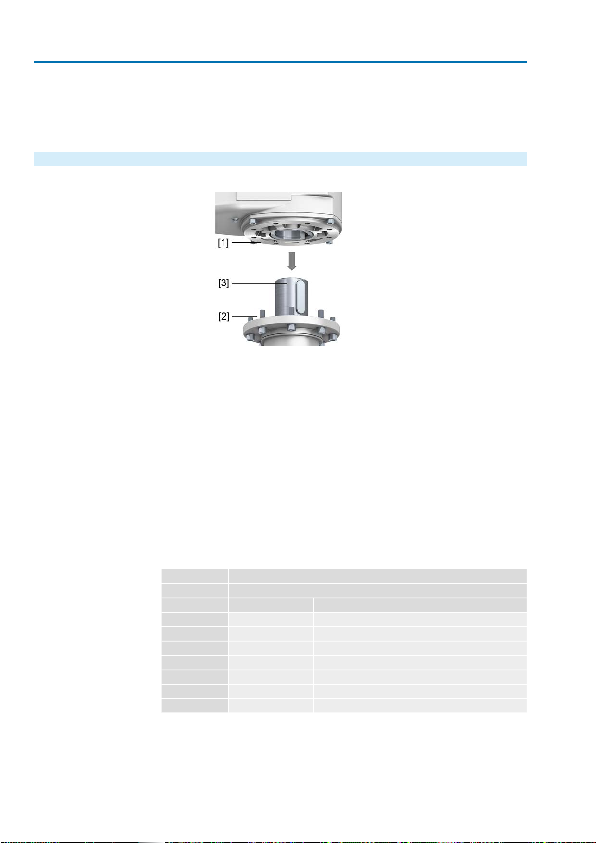
Mount input mounting
flange A flange is required for mounting a multi-turn actuator. Depending on the version,
the flange for mounting the multi-turn actuator is already fitted in the factory.
Figure 9: Mount flange to multi-turn gearbox
[1] Gearbox
[2] Parallel pin
[3] Input mounting flange
Assembly steps 1. Clean mounting faces, thoroughly degrease uncoated mounting surfaces.
2. Mount parallel pin [2].
3. Place input mounting flange [3] and fasten with screws.
4. Tighten screws crosswise with a torque according to table <Tightening torques
for screws> .
5. Place the multi-turn actuator on the spur gearbox and mount according to the
multi-turn actuator's operation instructions.Ensure that the spigot fits uniformly
in the recess and that the mounting faces are in complete contact.
Information: The multi-turn actuator can be positioned on the valve at every
90°.
12
GSTI 25.1 –GSTI 40.1 for use in nuclear power plants
Assembly (Inside/Outside Containment)

6. Fasten screws crosswise to a torque according to table.
Table 6:Tightening torques for screws
(for mounting multi-turn actuator and input mounting flange)
Tightening torque TA[Nm]Screws
Threads Strength class 8.8
25M8
51M10
87M12
214M16
431M20
Table 7:Tightening torques for screws
(for mounting multi-turn actuator and input mounting flange)
Tightening torque TA[Nm]Screws
Threads Strength class 10.9
37M8
75M10
128M12
314M16
615M20
5.4. Mount gearbox to valve
5.4.1. Overview of output drive types
Table 8: Overview on output drive types DescriptionApplicationValve attachment
➭page 13, Output drive type A
●for rising, non-rotating valve stem
●capable of withstanding thrust
●not appropriate for radial forces
A
➭page 15, Output drive types B/C
●for rotating, non-rising valve stem
●not capable of withstanding thrust
B, B1 –B4
C
5.4.2. Output drive type A
Figure 10: Output drive type A (example of A 10.2)
[1] Output mounting flange
[2] Stem nut
[3] Valve stem
Short description Output drive type A consisting of output mounting flange [1] with axial bearing stem
nut [2].The stem nut transmits the torque from the actuator hollow shaft to the valve
stem [3]. Output drive type A can withstand thrusts.
13
GSTI 25.1 –GSTI 40.1 for use in nuclear power plants
(Inside/Outside Containment) Assembly

5.4.2.1. Mount gearbox with output drive type A to valve
1. If output drive type A is already mounted to the gearbox:Loosen screws and
remove output drive type A.
2. Check if the flange of output drive type A matches the valve flange [4].
3. Apply a small quantity of grease to the valve stem.
4. Place output drive type A on valve stem and turn until it is flush on the valve
flange.
5. Turn output drive type A until alignment of the fixing holes.
6. Fasten screws [5] between valve and output drive type A [2] without completely
tightening them.
7. Fit gearbox on the valve stem so that the stem nut dogs engage into the output
drive sleeve.
➥The flanges are flush with each other if properly engaged.
Figure 11: Example of output drive A 10.2
8. Adjust gearbox until alignment of the fixing holes.
9. Fasten gearbox with screws [3].
10. Fasten screws [3] crosswise with a torque according to table.
Table 9:Tightening torques for screws
Tightening torque TA[Nm]Screws
Strength classThreads
10.98.8
3725M8
7551M10
12887M12
314214M16
615431M20
1,0571,489M30
2,1212,594M36
11. Turn gearbox with handwheel in direction OPEN until valve flange and output
drive type A are firmly placed together.
12. Tighten fastening screws [5] between valve and output drive type A crosswise
applying a torque according to table.
5.4.2.2. Finish machining of stem nut for output drive type A
This working step is only required if stem nut is supplied unbored or with pilot bore.
Information For exact product version, please refer to the order-related technical data sheet or
the AUMA Assistant App.
14
GSTI 25.1 –GSTI 40.1 for use in nuclear power plants
Assembly (Inside/Outside Containment)

How to proceed 1. Remove spigot ring [3] from output drive.
2. Remove stem nut [1] together with axial needle roller bearing [2].
3. Remove axial bearing washers [2.1] and axial needle roller and cage assemblies
[2.2] from stem nut [1].
Information: For output drive types A from size 35.2 and larger: Record the
order of axial bearing washers [2.1].
4. Drill and bore stem nut [1] and cut thread.
5. Clean the machined stem nut [1].
6. Place greased axial needle roller and cage assemblies [2.2] and axial bearing
washers [2.1] onto stem nut [1].
Information: For output drive types A from size 35.2: Observe correct order of
axial bearing washers [2.1].
7. Re-insert stem nut [1] with axial needle roller bearings [2] into output drive.
8. Screw in spigot ring [3] until firm seat against the shoulder.
5.4.3. Output drive types B/C
Figure 12: Mounting principle
[1] Flange/gearbox
[2] Hollow shaft
[3] Output drive sleeve (illustration examples)
[4] Valve shaft (example with key)
Short description Connection between hollow shaft and valve via output drive sleeve fixed to the hollow
shaft of the gearbox via retaining ring.
When exchanging the output drive sleeve, later retrofitting to a different output drive
type is possible
●Output drive type B:
Output drive sleeve with bore according to DIN 3210
●Output drive types B1/B3:
Output drive sleeve with bore according to EN ISO 5210
●Output drive types B2/B4:
Output drive sleeve with bore according to customer order
B4 including special bores like bores without keyway, square bore, hexagon
bore, internal splines
15
GSTI 25.1 –GSTI 40.1 for use in nuclear power plants
(Inside/Outside Containment) Assembly
●Output drive type C:
Output drive sleeve with dog coupling according to EN ISO 5210 or DIN 3338
Information The variants shown in the figure are not applicable for versions with reduction flange.
Information Spigot at valve flanges should be loose fit.
5.4.3.1. Mount gearbox with output drive types B to valve
Figure 13: Mounting output drive types B
[1] GSTI gearbox
[2] Valve
[3] Valve shaft
1. Check if mounting flanges fit together.
2. Check, if output drive of gearbox [2] matches the output drive of valve/valve
shaft [2/3].
3. Apply a small quantity of grease to the valve shaft [3].
4. Fit gearbox [1].
Information: Ensure that the spigot fits uniformly in the recess and that the
mounting faces are in complete contact.
5. Fasten gearbox with screws.
Information: We recommend applying liquid thread sealing material to the
screws to avoid contact corrosion.
6. Fasten screws crosswise to a torque according to table.
Table 10:Tightening torques for screws
Tightening torque TA[Nm]Screws
Strength classThreads
10.98.8
3725M8
7551M10
12887M12
314214M16
615431M20
1,0571,489M30
2,1212 594M36
16
GSTI 25.1 –GSTI 40.1 for use in nuclear power plants
Assembly (Inside/Outside Containment)
5.5. Accessories for assembly
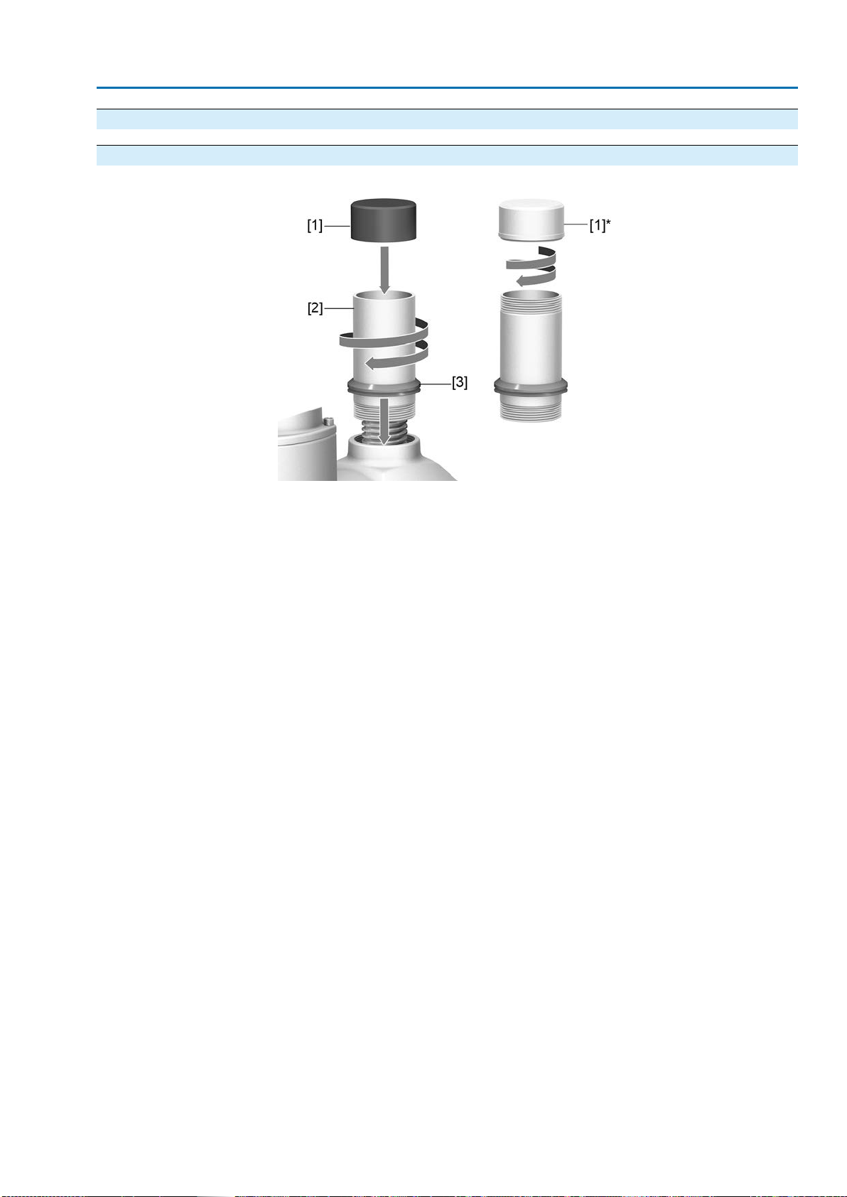
5.5.1. Stem protection tube for rising valve stem
Figure 14: Assembly of the stem protection tube
[1] Protective cap for stem protection tube (fitted)
[1]* Option: Protective cap made of steel (screwed)
[2] Stem protection tube
[3] V-seal
How to proceed 1. Seal all threads with hemp,Teflon tape, sealing agent or thread sealing mater-
ial.
2. Screw stem protection tube [2] into thread and tighten it firmly.
3. Push down the sealing ring [3] onto the housing.
4. Check whether protective cap [1] for stem protection tube is available, in perfect
condition and tightly placed on or screwed to the tube.
17
GSTI 25.1 –GSTI 40.1 for use in nuclear power plants
(Inside/Outside Containment) Assembly

6. Commissioning
6.1. Seating via multi-turn actuator
This chapter supplies basic information and instructions which should be considered
in addition to the operation instructions of the multi-turn actuator.
●The valve manufacturer has to determine whether the valve is limit or torque
seated.
●End position seating must be set in compliance with the operating instructions
pertaining to the multi-turn actuator.
●For limit seating, determine overrun, i.e. how much does the valve move after
the motor has been switched off?
●When setting the torque switching within the multi-turn actuator, make sure that
the tripping torque for both directions does not exceed the max. gearbox input
torque (refer to technical data or name plate).
●Set the torque switching within the multi-turn actuator to the following value to
prevent damage to the valve:
Tripping torque = valve torque/factor (refer to name plate)
18
GSTI 25.1 –GSTI 40.1 for use in nuclear power plants
Commissioning (Inside/Outside Containment)

7. Servicing and maintenance
Damage caused by inappropriate maintenance!
→Servicing and maintenance must be carried out exclusively by suitably qualified
personnel having been authorised by the end user or the contractor of the plant.
Therefore, we recommend contacting our service.
→Only perform servicing and maintenance tasks when the device is switched off.
AUMA
Service & Support AUMA offers extensive service such as servicing and maintenance as well as
customer product training.For the contact addresses, refer to our website
(www.auma.com).
7.1. Preventive measures for servicing and safe operation
●Before commissioning, perform visual inspection for grease leakage and paint
damage (corrosion).
●Thoroughly touch up any possible damage to paint. Original paint in small
quantities can be supplied by AUMA.
After six months and then once a year: Check gearbox for damage as well as for
grease and oil leakage.
7.2. Maintenance intervals
Recommendation for plants subject to strong vibration
●For plants subject to strong vibration, 6 months after commissioning and then
once a year: Check fastening screws between actuator and gearbox/valve for
tightness.If required, fasten screws while applying the tightening torques as
indicated in chapter <Assembly>.For screws sealed and secured with e.g.
thread sealing material, this action is not required.
Recommendation for grease change and seal replacement:
●If rarely operated (typically in buried service), the gearboxes are maintenance-
free.Grease change or re-lubrication is not necessary.
●If operated frequently (typically in modulating duty), we recommend changing
both grease and seals after 4 –6 years.
Gearing damage due to using inappropriate grease!
→Only use original lubricants supplied by AUMA.
→Do not mix lubricants.
When deployed in areas where dust formation represents a potential explosion
hazard, perform visual inspection for deposit of dirt or dust on a regular basis.Clean
devices if required.
Check gearbox for unusual running or grinding noise or vibration which might be an
indication of bearing or gear damage.
7.3. Disposal and recycling
Our devices have a long lifetime. However, they have to be replaced at one point in
time.The devices have a modular design and may, therefore, easily be separated
and sorted according to materials used, i.e.:
●Various metals
●Plastic materials
●Greases and oils
The following generally applies:
●Greases and oils are hazardous to water and must not be released into the
environment.
19
GSTI 25.1 –GSTI 40.1 for use in nuclear power plants
(Inside/Outside Containment) Servicing and maintenance

●Arrange for controlled waste disposal of the disassembled material or for sep-
arate recycling according to materials.
●Observe the national regulations for waste disposal.
20
GSTI 25.1 –GSTI 40.1 for use in nuclear power plants
Servicing and maintenance (Inside/Outside Containment)
This manual suits for next models
1
Table of contents
Other AUMA Industrial Equipment manuals


Popular Industrial Equipment manuals by other brands


ABB
ABB SACE Emax 2 E1.2 Instruction handbook

Hunter
Hunter Revolution Series Operation instructions

Spectris
Spectris PARTICLE MEASURING SYSTEMS HPGP 101-C Operation manual

Siemens
Siemens SITOP UPS501S operating instructions

SCHUNK
SCHUNK ROTA NCX Assembly and operating manual

Kitagawa
Kitagawa BS300 instruction manual