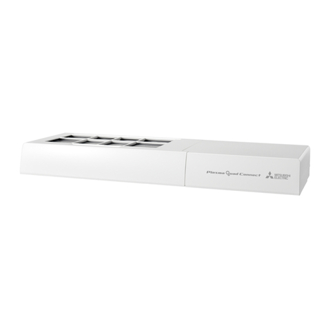
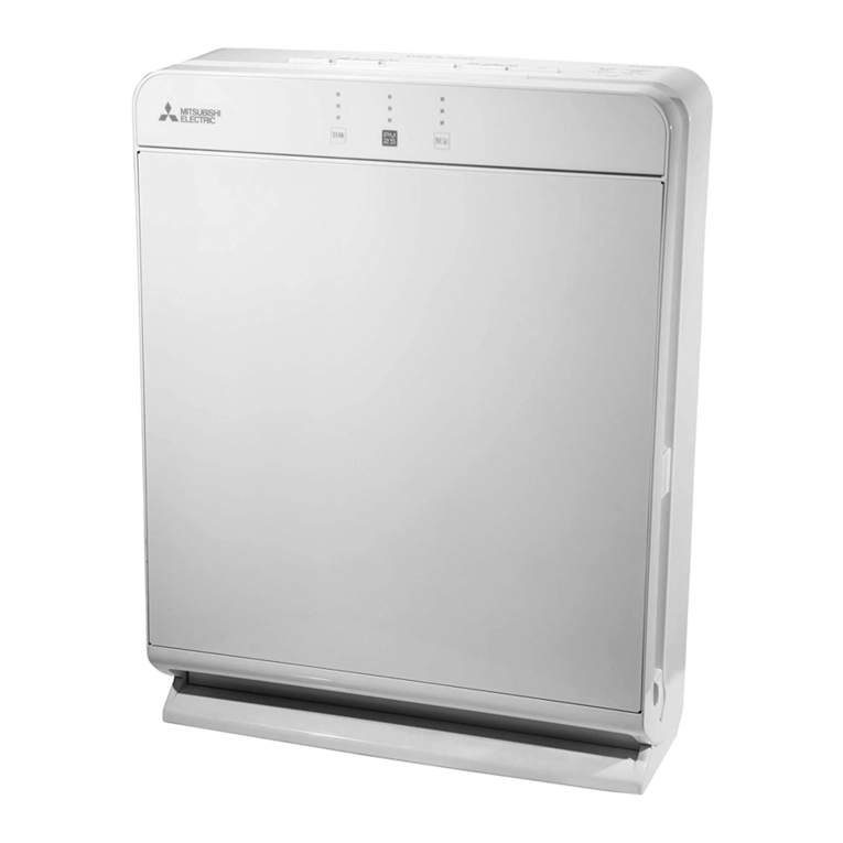
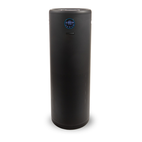
Mitsubishi Electric MA-E100R-E User manual

CONTENTS
Full Version Instruction Manual ...................................................................2
1. Safety Precautions.................................................................................3
2. Names and Functions of Parts...............................................................4
3. Features.................................................................................................5
4. ProductSpecications............................................................................6
5. External Dimensions ..............................................................................7
6. Electrical Wiring Diagram.....................................................................10
7. Control Outline .....................................................................................12
8. Technical Points ...................................................................................15
9. Installation Procedures.........................................................................16
10.Precautions for Troubleshooting...........................................................17
11.Troubleshooting Procedures ................................................................18
12.Troubleshooting....................................................................................24
13.Routine Inspection and Maintenance...................................................25
14.Service Inspection List .........................................................................27
15.Precautions for Disassembly and Reassembly....................................28
16.Disassembly and Reassembly.............................................................30
17.Parts Catalog........................................................................................41
AIR PURIFIER 2020
SERVICE MANUAL No.MAW-E-20020
Model MA-E100R-E
Sold from 2020

2
Full Version Instruction Manual
This product includes the brief version of the instruction manual.
The full version of the instruction manual can be downloaded from the website below.
Manual Download
http://www.mitsubishielectric.com/ldg/ibim/
EN This manual is brief version.
Go to the above website and choose language to download full version
INSTRUCTION MANUAL.
ES Este manual es una versión abreviada.
Visite el anterior sitio web y elija el idioma para descargar la versión
completa del MANUAL DE INSTRUCCIONES.
IT Questo manuale è una versione sintetica.
Visitare il sito Web indicato sopra e selezionare la lingua per scaricare la
versione integrale del MANUALE DI ISTRUZIONI.
FR Ce manuel est une version abrégée.
Rendez-vous sur le site Web ci-dessus et choisissez la langue pour
télécharger la version complète de la MANUEL D’INSTRUCTIONS.
DE
Diese Anleitung ist eine Kurzversion.
Besuchen Sie die oben stehende Website und wählen Sie die Sprache aus,
um die vollständige Version von BEDIENUNGSANLEITUNG herunterzuladen.
PL Niniejsza instrukcja to wersja skrócona.
Odwiedźpowyższąstronęinternetowąiwybierzjęzyk,abypobraćpełną
wersjęINSTRUKCJAOBSŁUGI.
NL Deze handleiding is een beknopte versie.
Ga naar de bovenstaande website en kies een taal om de volledige
HANDLEIDING te downloaden.
PT Este manual é uma versão abreviada.
Aceda ao site Web acima indicado e seleccione o idioma pretendido para
descarregar a versão completa das MANUAL DE INSTRUCOES.
BG Товаръководствоесъкратенаверсия.
Посететегорепосоченияуебсайтиизберетеезик,задаизтеглитепълна
версиянаРЪКОВОДСТВОЗАПОТРЕБИТЕЛЯ.

3
WARNING
Do not use a damaged power cord and
plug, or a loose power outlet.
This may cause electric shock, short circuit, or
fire.
Do not damage the power cord and
plug.
Do not unnecessarily bend, pull, twist, or bind the
power cord, place it close to a hot object, place a heavy
object on it, trap it between objects, or modify it.
•If the power cord is damaged, it must be replaced by
the manufacturer, its service agents, or a similarly
qualified person to avoid hazards.
This may cause damage, resulting in fire or electric
shock.
(Also take care that a pet does not bite the power cord.)
Do not repair, disassemble, or modify
the unit.
This may cause fire or electric shock.
For repairs, contact the retail store where you
purchased the product.
Do not put a wire, pole, other foreign
object or a finger into an air inlet,
outlet, rotating units or any other
opening into the unit.
This may cause electric shock or injury.
Use a 220-240 V AC power outlet.
Using other than a 220-240 V AC power outlet may
cause electric shock, short circuit, or fire.
Remove the power plug before
cleaning. Also, do not remove the
power plug with a wet hand.
This may cause electric shock or injury.
Remove dust from the power plug
regularly.
If dust accumulates, humidity, etc. may cause an
insulation failure, resulting in fire.
If the unit is operating abnormally or
fails, stop using it immediately.
• The unit does not operate when the power switch
is turned ON.
• The unit, power cord, or plug is abnormally hot.
• There is an abnormal noise or vibration during
operation.
• There is a burning smell.
• The operating sound is abnormally loud.
• Mounting screws are corroded or loose.
• The earth leakage circuit breaker trips frequently.
• There is another abnormality or failure.
Failure to do so may cause fire, electric shock, or
injury.
Immediately turn OFF the power switch and disconnect
the power plug, and then contact the retail store.
Do not allow flammable gas to be
sucked inside or use the unit where
flammable gas accumulates.
(Factory, beauty salon, etc.)
This may cause fire.
Do not use the unit in a location with the
oily smoke of machine oil or other oil.
This may cause cracking, resulting in electric shock.
Do not place the unit close to flammable
objects or objects lit with fire, such as
cigarettes or incense sticks.
This may cause a fire.
Do not stand on, sit on, or lean on the
unit, or place objects on it. Do not pull
the louvre with your fingers. Do not
place in an unstable location.
This may cause the unit to topple or fall and cause injury.
Do not wipe the unit
with benzene or thinner
or spray insecticide or
other chemicals onto it.
This may cause electric shock,
fire, or cracking and cause injury.
Do not operate the unit when using an
insecticide that produces smoke.
An accumulation of chemical components may be
released from the air outlet, and be harmful to health.
After using an insecticide, ventilate the area sufficiently
prior to operating the unit.
Do not move the unit except by holding
the handles.
This may cause the unit to topple and fall, or pinch
fingers, causing injury.
Do not install the unit where water may
be spilt onto it or where there is a lot
of humidity such as in a bathroom.
This may cause electric shock.
Should water or other liquid be spilt onto the unit, stop
operation and remove the power plug, and then contact
the retail store where you purchased the product.
Insecticide
Do not lay the unit
horizontally when
removing a filter.
This may cause dust to enter inside,
resulting in fire or electric shock.
Do not use a damaged filter
or operate the unit while a
filter is removed.
This may cause dust to enter inside,
resulting in fire or electric shock.
Do not come close to the main unit
while the unit is rotating.
In particular take care regarding children.
If you are sandwiched between the wall while rotating,
it may cause an injury.
Place the unit in a location where it
will not bump into a wall or furniture
while the unit is rotating.
This may cause damage to the wall or furniture.
Hold the bottom of the inlet panel when
installing the inlet panel.
If the top of the inlet panel is held, your hand can be
trapped causing injury.
When using the unit in combination
with a combustion appliance, ventilate
the room occasionally.
Carbon monoxide cannot be removed from the air,
so not ventilating the room may cause carbon
monoxide poisoning.
When disconnecting the power plug, pull
it out straight while holding not the cord
but the power plug.
Failure to do so may cause
electric shock or a short
circuit resulting in fire.
When the unit will not be used for a
long time, disconnect the power plug.
Failure to do so may cause the insulation to deteriorate,
resulting in fire from a short circuit or an electric shock.
Safety Precautions CAUTION
To prevent personal injury, injury to others, or property damage, the following precautions must be observed.
WARNING
Indicates a hazard caused by
mishandling that may result in
death or serious injury.
CAUTION
Indicates a hazard caused by
mishandling that may result in
a minor injury or damage to the
home and its contents.
The following categories describe hazards caused by mishandling
and their levels.
Prohibited
Beware of
rotating
device
Do not
disassemble
Do not
use near
water
The meanings of the graphic symbols used in this manual and on the
unit are as follows.
Observe
instructions
This appliance can be used by children aged from 8 years and above and persons with reduced physical, sensory
or mental capabilities or lack of experience and knowledge if they have been given supervision or instruction
concerning use of the appliance in a safe way and understand the hazards involved. Children shall not play with the
appliance. Cleaning and user maintenance shall not be made by children without supervision.
Note: This page is extracted from the full version instruction manual.
1. Safety Precautions

4
Odor monitor
The state of air contamination
from cigarette odor and other
odors is detected by the odor
sensor and then indicated.
PM2.5 monitor
The state of air contamination from
PM2.5 and other small particles is
detected by the PM2.5 Sensor and then
indicated.
Dust monitor
The state of air contamination from pollen,
dead bodies of mites, and other large
particles is detected by the PM2.5 Sensor
and then indicated.
PM2.5 Sensor
This optical sensor detects the
number of particles.
The monitor indications are divided
into “PM2.5” and “Dust” according
to the size of the particles.
* Particles less than 0.5 μm are not
detected.
Adjusting the Sensitivity of
the PM2.5 Sensor P.14
z Operation mode lamps (white)
P.11
Indicate the current operation mode.
z Power switch P.11
Turns ON/OFF the power.
z Auto switch P.11
Switches the operation mode
between Normal and Night.
z Manual switch P.11
Switches the operation mode
between Low, Middle, and High.
z Operation switch lamps (white) P.11
Lights when the power switch is turned ON.
Main Unit Control Panel
Front
Rear
Odor sensor
P.9, 15
Detects cigarette odor and other odors.
Control
panel Human sensing P.12–13
Special washable activated
charcoal filter
(Activated charcoal filter) <×2>
Consumable part P.17
Pre-filter <×2>
P.10, 15
Blower fan
Automatic rotation
P.12–13
Two-layer HEPA filter
Consumable part P.17
Inlet panel
Handles (on left and right) P. 6
Used when moving the unit.
Air inlet
PM2.5 Sensor P.9, 14–16
Detects air contamination from cigarette smoke, dust, and pollen.
Filter replacement sticker
P.10, 17
Write the filter use start date.
This will serve as a rough guide for filter replacement.
Power cord
<High Efficiency Particulate Air filter>
A highly efficient filter capable of filtering at least 99.97% of
particles with a diameter of 0.3 μm (micrometer).
What is a HEPA filter?
z Clean monitors (orange/red)
The state of air contamination detected with the
odor sensor and PM2.5 Sensor is indicated by
lamps lighting in three steps.
<How to read the clean monitors>
z Replace Filter lamp (red) P.17
Lights to notify you when it becomes time to replace
the HEPA filter.
Odor sensor
This semiconducting sensor
detects odors and other gases. It
also responds to wind from air
conditioners, electric fans, and
other appliances, odorless gases,
and perfumes.
Names and Functions of Parts
Air outlet/Louvre P.13
Air is
contaminated
Air is clean
Lit in
red
Lit in
orange
Off
z Reset button P.17
(The button is located at top right of the unit and
accessible by removing the inlet panel.)
Cancels the Replace Filter lamp.
z Human sensing lamp (green/orange)
zLights according to the clean monitors.
(
When clean monitor lamps are lit: Orange
)
When clean monitor lamps are off: Green
zFlashes in green during the human sensing detection operation.
<Size of dirt particles>
Viruses
Dust, particles harmful to the lungs
Feces and dead bodies of mites
Cigarette smoke particles
PM2.5 monitor
Dust monitor
Pollen
0.01 0.1 0.5 2.51 10 100 (μm)
PM2.5
Mainly particles of 2.5 μm or less
Mainly particles greater than 1 μm
2. Names and Functions of Parts Note: This page is extracted from the full version instruction manual.

5
Human Sensing and Automatic Rotation Ensure that the
Air Around People and All Over the Room is Purified.
The Air Purifier Actively Purifies Air by Moving Itself.
z Human Sensing P.12–13
Human Sensing detects a person’s location while
turning left and right.
z Automatic Rotation P.12–13
The air inlet and outlet are moved to the optimal
direction depending on a person’s location.
z PM2.5 Sensor
Improved small particle detection speed and accuracy.
It can even detect 0.5-μm particles.
z Large Air Volume
The maximum air volume of 600 m3/h facilitates quick suction
of a large amount of pollen and dust.
z Support for PM2.5
Catches 99%* of particles from 0.1 to 2.5 μm.
Consideration is not given to new particles entering from outdoors due to, for example, ventilation.
z PM2.5 is a generic term for fine particulate matter of 2.5 μm or less.
z The removal of fine particulate matter less than 0.1 μm with this air purifier has not been verified.
Also, this air purifier is not capable of removing all harmful substances from the air.
z This is the effect achieved in a 30-m3enclosed space, and is not the result of verification in a space that is in actual use.
* <Testing laboratory> SHANGHAI ENTRY-EXIT INSPECTION AND QUARANTINE BUREAU MECHANICAL & ELECTRICAL PRODUCTS
TESTING CENTER
<Test method> Performed by regulating the initial concentration of particulate matter within the range of (5.0 ± 1.0) mg/m3in a 30-m3test
space
<Test results> 99% eliminated in 20 minutes
z Two-layer HEPA Filter
Comes equipped with a HEPA filter that catches 99.97% of 0.3-μm pollen and house dust.
z Reduction of Airborne Viruses*
* This is the effect on airborne viruses achieved after operation for 11 minutes in a test space of a 25 m3, and is not the result of verification
in a space that is in actual use.
Manual operation (High) (600 m3/h)
<Testing body> Virus Research Center, Sendai Medical Center, National Hospital Organization
<Test method> The performance evaluation test of the voluntary standard (JEM1467) issued by The Japan Electrical Manufacturers’
Association was performed in a 25-m3test space.
<Test object> 1 type of airborne virus
<Test result> 99% reduction in 11 minutes
Features
What will happen if cleaning is not performed?
If a lot of dust adheres to the pre-filter and HEPA filter, performance may deteriorate remarkably.
Will all cigarette smoke be removed?
The air purifier can remove nicotine and other particles, but the room needs to be ventilated occasionally
because carbon monoxide (CO), a harmful substance contained in cigarette smoke, cannot be removed.
Furthermore, when a lot of cigarettes are smoked, cigarette odor may be emitted from the unit.
Frequently Asked Questions
3.Features Note: This page is extracted from the full version instruction manual.

6
Specifications
Model MA-E100R-E
Power supply 220-240 V AC, 50 Hz
Manual operation High Middle Low
Power consumption 82 W 19 W 7 W
Air volume 600 m3/h 300 m3/h 84 m3/h
Weight 13.4 kg
Dimensions 800 (H) × 320 (W) × 270 (D) mm
Cord length 1.8 m
4. ProductSpecications Note: This page is extracted from the full version instruction manual.

7
5. External Dimensions (Unit: mm)
320 mm
270 mm
800 mm

8
863
82.7
85°
250.2 (air outlet width)
128.1
49.1
141.5
250.6
(Unit: mm)

9
25 480
79 191
317
90.5
197
21.7 21.5
11.4
270
3729
250.6
90
PL indication
nameplate
Caution
nameplate
Unit
nameplate
270
81.5 249 800
18 737
666.6 66
29.6 383.7 59
55.5
4
328.6
36
5
320
320
233
81.5
Standby power
indication
nameplate
(Unit: mm)

10
6. Electrical Wiring Diagram
(1) Wiring Diagram
P001
P111 P207 P208
P104
P107
P108
P213
P120 P214P003
P121 P002
P105
P211
P203
P103
Stepping motor for
human sensing unit
Human sensing unit
LED circuit board
Odor sensor
circuit board
Red
Blue
Yellow
White
White
Blue
Blue
Blue
Yellow Yellow
Display operation circuit board
Louver
Louver
Relay
connector
Dust
sensor
Blower fan
Blower fan Power supply control
circuit board
Power
supply
White
Stepping motor
for automatic
rotation turntable
Relay connector
Automatic rotation position
detection sensor
Automatic rotation position
detection sensor
Automatic rotation position
detection sensor

11
(2) Circuit Board Diagrams
Power supply control circuit board Display operation circuit board
Odor sensor circuit board LED circuit board

12
7. Control Outline
(1) Function Operation List
Operation status
Operation OFF
Automatic operation Manual operation
Night Normal Low Mid High
Controlled devices
Blower fan A and B OFF ON ON ON ON ON
Automatic rotation turntable Stops at the
center Stops at the
center Moves and stops repeatedly
Human sensing unit Stops at the
center Stops at the
center Moves and stops repeatedly
Louver A and B CLOSE OPEN
LEDs
Operation mode OFF ON for the selected operation mode
Operation switch OFF ON
Odor monitor OFF ON/OFF
PM2.5 monitor OFF ON/OFF
Dust monitor OFF ON/OFF
Filter replacement OFF ONwhentheaccumulatedtimeforlterreplacementisreached
Human sensing unit OFF Green/Orange
Switches
Power Yes Yes Yes Yes Yes Yes
Manual No Yes Yes Yes Yes Yes
Auto No Yes Yes Yes Yes Yes
Reset Yes Yes Yes Yes Yes Yes
<Lamp Indication>
(1)Operation mode lamps (Low, Mid, High,
Night, and Normal)
• Operation mode is indicated.
• One lamp is lit during operation.
• The “Normal” lamp is lit by default (automatic
operation).
(2)Operation switch lamps
• The mode switches are indicated while operation is
ON.
(3)“Replace Filter” lamp
• The lamp is lit when the operation time reaches the
set value (approx. 4.5 years for “Low” operation and
approx. 8 months for “High” operation).
(4)Clean monitors
• The lamps are lit in accordance with the state of
odor, PM2.5, and dust contamination.
• The lamp color changes between “OFF”, “Orange”,
and “Red” depending on the level of contamination.
(5)Human sensing lamp
• The lamp is lit in accordance with the state of odor,
PM2.5, and dust contamination.
• The lamp color changes between “Green” and
“Orange” depending on the level of contamination.
(The lamp is always lit in “Green” except when it is
in the “Orange” state.)
• Thelampashesslowlywhiledetectingpeoplewith
the human sensing unit.
(2) Fan Control
Rank for Rotation Speed
1The fan rotation speed for each fan rank is controlled as follows.
2EEPROM holds the rotation speed data and pulse initial value.
Fan rank 1 2 3 4 5 6 7
Fan A rotating speed (rpm) 350 380 470 680 800 1050 1380
Fan B rotating speed (rpm) 350 380 470 680 800 1050 1380
Air volume (m3/h) 84 102 150 240 300 450 600

13
(3) Operation Control
Automatic operation (Normal and Night)
1Normal
• Theamountofairowischangedinaccordancewiththelevelofodor,PM2.5,anddust
contamination.
• Thedirectionofairowischangedinaccordancewiththepositionofpeopleintheroom.
2Night
• A fan rank lower than the standard blower fan rank is set because priority is given to silent
operation.
• The LED lighting time is set to 1/2 and the brightness of each lamp is restricted.
• Thedirectionofairowisxedtothecenter.
Manual operation (Low, Mid, and High)
Operation is performed continuously at a certain air volume.
Operation mode Fan rank Air volume (m3/h)
Low 1 84
Mid 5 300
High 7 600
(4) Filter Replacement Lamp (Total Operation Time)
The blower fan operation time is counted and the lamp lights when the total time reaches approx. 4.5 years
in the case of the “Low” operation.
Operation mode Air volume (m3/h) Period Replacement timing (hour)
High 600 Approx. 8 months 7,744
Low 84 Approx. 4.5 years 38,720
(5) Switching the Sensitivity of the Dust Sensor
Setting procedure: While operation is OFF, press the “Auto” switch 3 times within 2 seconds.
• When switched from “standard sensitivity” to “high sensitivity”
The buzzer makes a “blip blip” sound and the PM2.5 monitor lamp (red) lights for 3 seconds.
• When switched from “high sensitivity” to “standard sensitivity”
Thebuzzermakesa“blip”soundandthePM2.5monitorlamp(red)ashesfor3seconds.
(6) Turning the Automatic Rotation Function ON/OFF
Setting procedure: While operation is OFF, press the “Manual” switch 3 times within 2 seconds.
• When switched from “automatic rotation OFF” to “automatic rotation ON”
The buzzer makes a “blip blip” sound and the dust monitor lamp (red) lights for 3 seconds.
• When switched from “automatic rotation ON” to “automatic rotation OFF”
Thebuzzermakesa“blip”soundandthedustmonitorlamp(red)ashesfor3seconds.

14
(7) Hotel Mode (No description in the instruction manual)
1HotelModeSpecications
1. Main power link
The last operation is remembered when the power is turned OFF and operation is performed in the
remembered operation mode when the power is turned back ON.
Example: The last set operation mode is remembered so if “Normal” is set and then the power plug
is pulled out or if the operation is turned OFF, the unit will automatically begin the “Normal” operation
next time.
2. Thelterreplacementlampdoesnotlight.
2How to Check Whether It Is Time for a Filter Replacement
Press the reset button once.
Ifitistimeforalterreplacement,theLEDlightsfor5seconds.
If no LED lights when you press the reset button, it is not time for a replacement.
CAUTION: Pressing the reset button for 2 or more seconds will clear the accumulated times.
3How to Set Hotel Mode and Normal Mode
1. Insert the power cord plug into the power outlet.
2. When operation is OFF, press the reset button 10 times within 10 seconds.
• When the mode is switched from normal mode to hotel mode
1The buzzer makes a “bleep” sound.
2All the odor monitor lamps and PM2.5 monitor lamp light.
• When the mode is switched from hotel mode to normal mode
1The buzzer makes a “blip blip” sound.
2All operation mode lamps light.
* The set mode is retained even if the plug is removed from the power outlet.

15
<Automatic rotation operation range>
The automatic rotation automatically turns the main unit according to the person’s location detected
by the human sensing. The main unit is stopped at any of 1to 5in the figure on the right.
zThe operation range is approx. 90 degrees. It differs from the detection range of the human sensing.
zThe main unit may not turn to face a person when, for example, the human sensing has detected
multiple persons.
zWhen the human sensing detects a person directly in front of the main unit, the main unit is not
moved and remains facing forward.
zThe automatic rotation will not operate when the main unit hits a wall or other object because at
least 20 cm of space was not provided around it, when the main unit hits an object nearby that
prevents turning, or when the main unit is restrained from moving.
<Louvre operation range>
The louvre is stopped at any of 1to 3in the figure on the right.
1 When a person is not detected by the human sensing while Normal operation mode is selected
→Air is blown all over the room including far away locations.
2 When a person is detected by the human sensing while Normal operation mode is selected
→Air flow is controlled so that air is not blown directly at a person.
3 When manual operation is selected
→Air flow is controlled so that sufficient air-flow volume is maintained.
Features Human sensing detection
Operations (when Normal Operation Mode is Selected)
The direction to a person’s location is detected by the human sensing. The air inlet and outlet are moved by the automatic rotation and the
optimal air flow is created by the louvre according to the person’s location.
z The human sensing detects a person’s location within a range of approx. 150 degrees while turning left and right.
(The human sensing lamp flashes green while the human sensing is performing the detection operation.)
z The human sensing measures the indoor temperature in the room and determines the direction to a person’s location from variations in
the temperature.
z The human sensing operates only when the main unit is stopped and faces forward.
(The human sensing does not operate when the automatic rotation is operating or the main unit faces a direction other than the forward direction.)
A person cannot be detected in locations such as the following.
z Outside of the detection area z Where there is an obstacle (furniture or other object) to the main unit
A person cannot be detected correctly in cases such as the following.
z When there is something that changes the temperature
significantly within a short period of time (e.g., television, air
conditioner, refrigerator)
z When the room temperature or the temperature of the floor and
walls is high (rough guide: 30°C or more)
z When the room temperature or the temperature of the floor and
walls is low (rough guide: 8°C or less)
z When skin is not exposed because the person is under a blanket
or wearing a lot of clothes
z When the heat source cannot be detected such as when there is a
small child or pet or a person wearing a lot clothes
z When the distance to the person is short (rough guide: 0.5 m or
less)
z When the distance to the person is long (rough guide: 6 m or
more)
z When the person is not moving much
<When the human sensing cannot detect a person>
z When the human sensing cannot detect a person and none of the above apply, perform the
check described in the following procedure.
(Perform the check when the room temperature is 15 to 28°C.)
1
Turn ON the power switch and stand in the position indicated by “A” in the figure on the right.
2 When the human sensing turns right and passes you, move to the position indicated by
“B” in the figure on the right.
→Operation is normal if the main unit is moved to face you (position indicated by “B”) by
the automatic rotation.
<Turning off the human sensing> P.14
When operation is started, the human sensing begins detection. The human sensing turns left and right
while the main unit remains facing forward. After completing one left and right movement (takes approx.
two minutes), the human sensing determines the direction to a person’s location.
<When a person is present>
1 The main unit is turned toward the person’s location automatically and then stopped by the
automatic rotation.
2 The louvre controls the air-flow direction so that air does not blow directly at the person.
3 Contamination is monitored while removing the dust in the area around the person.
4 When contamination in the room is detected by the PM2.5 Sensor and odor sensor, the air
volume is changed automatically.
After approx. 15 minutes, the main unit is turned to face forward and then stopped by the
automatic rotation.
The human sensing turns left and right again to detect the direction to a person’s location.
z If more than one person is detected, the automatic rotation stop position is
determined automatically depending on the number of persons and the direction to
the persons.
<When a person is not present>
1 The louvre controls the air-flow direction so that air is blown over the entire room while the
main unit remains facing forward.
2 Contamination is monitored while removing the dust in the entire room.
3 When contamination in the room is detected by the PM2.5 Sensor and odor sensor, the air
volume is changed automatically.
After approx. three minutes, the human sensing turns left and right again to detect the
direction to a person’s location.
About Human Sensing, Automatic Rotation, and Louvre
The human sensing turns approx. 150 degrees in the left and
right directions to detect the direction to a person’s location.
The air inlet and outlet are moved by the automatic rotation
which moves the main unit according to the person’s location.
The optimal air flow is created by the louvre in order to clean the
area around the person.
Air flow is controlled so that air is not
blown directly at a person.
Air is blown over the entire room.
<Rough guide on detection area>
Approx. 6 m Approx. 150 degrees
(When room temperature is 24°C)
Move
A B
1 to 2 m 20 to 50
degrees
1
234
5
Approx. 90
degrees
1
23
Note: This page is extracted from the full version instruction manual.
8. Technical Points

16
zInstall with space around this unit
zIf this unit is installed in a place that is not level, or a place that is
unstable (on a carpet or tatami mat, etc.), it may vibrate.
zThe main unit is rotated by the automatic rotation, so install with
20 cm or more of space around this unit.
zBefore Installation
The air inlet, outlet, PM2.5 Sensor, and odor sensor are
located as shown in the figure on the right.
Take care regarding the following points.
Do not obstruct or place objects in front of the air inlet or outlet.
→The air purification function will be impaired.
Do not obstruct the odor sensor.
→It will not be possible to detect odors.
Do not obstruct the PM2.5 Sensor.
→It will not be possible to detect dirt.
This unit cannot be used hanging from a wall.
Odor sensor
(inside inlet panel)
PM2.5 Sensor
Outlet
Inlet
Inlet
zInstallation Procedure
zInstall in a location with good air circulation.
zTake care regarding the following points
during installation.
If installed facing an air-
conditioner, the circulation
effect is increased.
60 cm or more
20 cm or more
20 cm
or more
20 cm
or more
20 cm
or more
Do not place hot items such as a stove near
or on top of this unit.
This may cause a malfunction,
deformation, or discoloration.
Do not use in a place
subject to direct sunlight.
This may cause deformation
or discoloration.
Install this unit 1 m or more away from
television, cordless telephone, air
conditioners, personal computers,
fluorescent light fittings, etc.
This may cause radio wave
interference with the other
equipment.
Do not place on soil or sand.
Do not place on a floor with
much soil or sand.
This may cause a malfunction.
Installation
9. Installation Procedures Note: This page is extracted from the full version instruction manual.

17
10. Precautions for Troubleshooting
The following precautions should be observed in order to perform troubleshooting safely and correctly.
The following categories describe hazards caused by mishandling and their levels.
WARNING
Mishandlingmayresultinfatalorseriousinjury,orre.
CAUTION
Mishandling may result in injuries or damage to your home or property, etc.
Forbidden Always follow the
instructions Alert
Meanings of graphic symbols are explained below.
Remove the power plug
from the outlet.
Failure to do so may cause electric
shock and/or injuries.
When performing work with
the power on, be careful not
to touch the live part.
This may cause electric shock.
Do not touch a rotating
object until it completely
stops.
The rotating object may catch your
hand, etc., and result in injuries.
Do not work with wet hands.
This may cause electric shock.
Check the wiring diagram
before wiring processing.
Failure to do so may cause ignition,
generation of smoke, and/or
malfunction.
After the work, lay the wire
out as it was before.
Failure to do so may cause ignition,
generation of smoke, and/or
malfunction.
Unplug
Electric shock
Do not touch
No wet hands
Check Return to
as it was
WARNING
Wear protective gloves.
Failure to do so may result in injuries
by the edge of metal, electric shock,
and/or burns caused by contact with
hot section.
Keep children away.
Failure to do so may cause electric
shock and/or injuries when moving the
product or using a measuring device.
Wear gloves Keep away
CAUTION

18
11.Troubleshooting Procedures
(1) Symptoms and Remedies
Symptom Check Item Remedy
1. Blower fan
(motor) does not
rotate (power
does not turn
ON).
• How to determine whether the DC motor has a malfunction
The following table shows the values for a normal motor that was measured with a
multimeter.
Themotorhasamalfunctionifanyvalueisverydierentfromthenormalvalue.
Measurement method (pin number of P107 and P108 connectors)
Tester + terminal Tester - terminal
Tester measurement mode
Normal value Malfunction diagnosis
Pin 1 (red) Pin 4 Resistance Innity
Motor internal circuit breakdown
Pin 6 (white) Pin 4 Resistance 10sofkΩ
Motor internal circuit breakdown
Pin 7 (yellow) Pin 4 Resistance 10sofkΩ
Motor internal circuit breakdown
Pin 8 (blue) Pin 4 Resistance Innity
Motor internal circuit breakdown
Pin 4 (black) Pin 1 Diode 0.5 to 2 V
Motor internal circuit breakdown
Any pin
Outer casing of motor
Resistance Innity Motor insulation breakdown
The above is the diagnostic method for when the motor is isolated.
Regardless of the rotation state, do not test the motor when the connectors are connected.
2. Dust is not
collected (air
volume is low).
3. Deodorizing is
not performed
(deodorizing
performance is
low).
4. The odor monitor
does not work.
5. The PM2.5
monitor or dust
monitor does not
work.
Is an operation mode lamp
lit when you press the
operation switch?
Check the continuity of the current fuse.
The current fuse has blown.
Replace the power supply control circuit board.
* Pull out the power plug before checking.
Check the connection cables and connectors
of the display operation circuit board and
power supply control circuit board.
Check the output voltage at the
connectors P107 and P108 of the power
supply control circuit board within 45
seconds after turning ON the power.
If 280 VDC is not output normally between
the pins 1 and 4, 15 to 19 VDC is not output
normally between the pins 6 and 4, and 1 to
6 VDC is not output normally between pins 7
and 4, replace the power supply control circuit
board. If the voltages are output normally,
replace the blower motor (pin 4 is GND).
Not
lit
Lit
Isthepre-ltercloggedwith
dust? Removethedust(cleanthepre-lterand
HEPAlter).
ReplacetheHEPAlterwithanewone.
Isthelterreplacementlamp
lit? Soak and wash the activated charcoal
lter.
Replacetheactivatedcharcoallterwitha
new one.
Not lit
Lit
Place perfume, hair tonic,
alcohol for disinfection, or
the like in front of the unit
and check the response.
Was there no response?
Replace the odor sensor.
* Response will be slow immediately after
the power switch is turned ON because the
odor sensor is performing the preparation
operation. Perform operation for about 5
minutes and then perform the check.
YES
Rub tissue paper for 20 seconds
and check the response. Was
there no response?
Replace the dust sensor.
YES

19
(2) Test Modes
Error History Check Mode
1Starting procedure
A.When the power switch is OFF, press the “Manual” switch and “Auto” switch 3 times
simultaneously.
B.Turn ON the power switch within 2 seconds.
C.After the error history check mode starts up, select a mode using the “Manual” switch.
D.Themodechangesas0→1→2→3→4...7→0,anditisindicatedwithLEDs.
E.Mode 0: The most current error, Mode 7: The oldest error
F. Turn OFF the power switch to end the error history check mode.

20
Error Indications and Remedy Guidelines
Indication
Error code A1 A6
Error item RAM check Watch dog error (main stop)
Cause and remedy Microcomputer malfunction Microcomputer malfunction
Part name Power supply control circuit board Power supply control circuit board
Condition — —
Connector — —
Terminal to check — —
Normal value — —
Indication
Error code F0 F2
Error item Locked blower fan A (upper side) Locked blower fan B (lower side)
Cause and remedy Check the operation of the blower motor.
Check that the connector P107 is inserted properly. Check the operation of the blower motor.
Check that the connector P108 is inserted properly.
Part name Blower motor Blower motor
Condition Room temperature Room temperature
Connector P107 P108
Terminal to check Each terminal Each terminal
Normal value See “How to determine whether the DC motor has a malfunction”. See “How to determine whether the DC motor has a malfunction”.
Other manuals for MA-E100R-E
1
Table of contents
Other Mitsubishi Electric Air Cleaner manuals

Mitsubishi Electric
Mitsubishi Electric Plasma Quad Connect MAC-100FT-E User manual

Mitsubishi Electric
Mitsubishi Electric MA-E100R-E User manual

Mitsubishi Electric
Mitsubishi Electric MA-E85R-E User manual

Mitsubishi Electric
Mitsubishi Electric MA-E85R-E User manual

Mitsubishi Electric
Mitsubishi Electric Plasma Quad Connect MAC-100FT-E User manual

Mitsubishi Electric
Mitsubishi Electric MA-E85R-A User manual

Mitsubishi Electric
Mitsubishi Electric MA-EF503HS-U User manual

Mitsubishi Electric
Mitsubishi Electric Plasma Quad Connect MAC-100FT-E User manual

Mitsubishi Electric
Mitsubishi Electric Fresh Master GUF-100RDH3 User manual