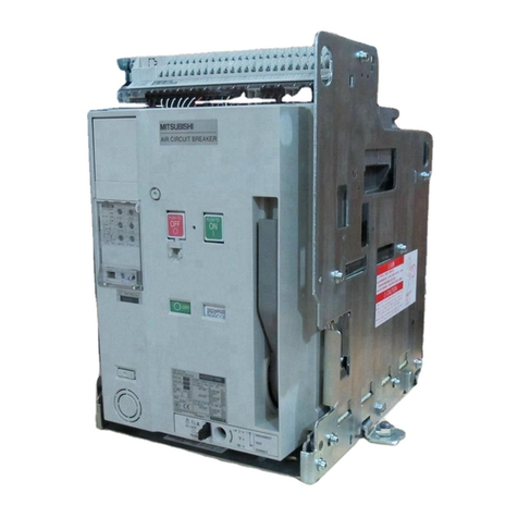
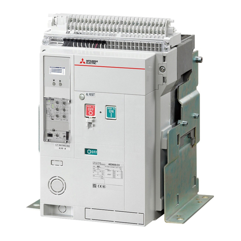
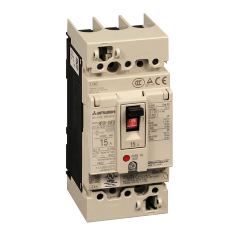
Mitsubishi Electric V Series User manual

Y-0794 2009(MEE)
HEAD OFFICE: TOKYO BLDG., 2-7-3 MARUNOUCHI,
CHIYODA-KU, TOKYO 100-8310, JAPAN
Printed September 2020 All trademarks acknowledged.
For Safety : Please read the instruction manual carefully before using the products in this catalog. Wiring and connection
must be done by the person who has a specialized knowledge of electric construction and wiring.
http://www.mitsubishielectric.com/fa/products/lvd/lvcb/index.html
FA Global Site
Eco Changes is the Mitsubishi Electric Group’s environmental statement,
and expresses the Group's stance on environmental management.
Through a wide range of businesses, we are helping contribute to the
realization of a sustainable society.
MITSUBISHI Low Voltage Air Circuit Breakers
Low Voltage Air Circuit Breakers
FACTORY AUTOMATION

32
Warranty
1
OVERVIEW
Warranty 4
Product Outline 6
Product Features 7
Product Specication 10
Closing method 11
Appearance and Product structure 12
Connections 14
Accessories 15
Electronic trip relay 22
Wiring diagram 30
Outline dimensions 32
Technical information 35
Ordering information 40
Service network 42
2
1
9
5
3
11
12
13
7
10
6
4
8
Contents
Global Player
GLOBAL IMPACT OF
MITSUBISHI ELECTRIC
We bring together the best minds to
create the best technologies. At
Mitsubishi Electric, we understand that
technology is the driving force of change
in our lives. By bringing greater comfort
to daily life, maximizing the efficiency of
businesses and keeping things running
across society, we integrate technology
and innovation to bring changes for
the better.
Mitsubishi Electric is involved in many areas including the following:
Energy and Electric Systems
A wide range of power and electrical products from generators to large-scale displays.
Electronic Devices
A wide portfolio of cutting-edge semiconductor devices for systems and products.
Home Appliance
Dependable consumer products like air conditioners and home
entertainment systems.
Information and Communication Systems
Commercial and consumer-centric equipment, products and systems.
Industrial Automation Systems
Maximizing productivity and efficiency with cutting-edge automation technology.
Through Mitsubishi Electric’s vision, “Changes for the Better“ are possible for a brighter future.
2 43
YOUR SOLUTION PARTNER
Automation solutions
MitsubishiElectric offers a wide range of automation equipment from PLCsand HMIs to
CNC andEDM machines.
A NAME TO TRUST
Since its beginnings in 1870, some 45
companies use the Mitsubishi name,
covering a spectrum of finance,com-
merce and industry.
The Mitsubishi brand name is recognized
around the world as a symbol of
premium quality.
Mitsubishi Electric Corporation is active
in space development, transportation,
semi-conductors, energy systems,
communications and information pro-
cessing, audio visual equipment and
home electronics, building and energy
management and automation systems,
and has 237 factories and laboratories
worldwide in over 121 countries.
This is why you can rely on Mitsubishi
Electric automation solution - because
we know first hand about the need for
reliable, efficient, easy-to-use automation
and control in our own factories.
As one of the world’s leading compan-
ies with a global turnover of over 4 trillion
Yen (over $40 billion), employing over
100,000 people, Mitsubishi Electric has
the resource and the commitment to
deliver the ultimate in service and support
as well as the best products.
Medium voltage: VCB, VCC
Power monitoring, energy management
Compact and Modular Controllers
Inverters, Servos and Motors
Visualisation: HMIs
Numerical Control (NC)
Industrial / Collaborative Robots
Processing machines: EDM, Lasers, IDS
Transformers, Air conditioning, Photovoltaic systems
Low voltage: MCCB, MCB, ACB
* Not all products are available in all countries.

4 5
Warranty
Warranty
11
(2) The products listed in this catalogue are designed and manufactured as general-purpose products for application
to the general industry field. Therefore, the warranty does not apply to the following special uses.
[1] The use that has a significant influence on the public facilities such as nuclear power plants and other power
plants of power companies.
[2] The use for railway companies, government offices, etc. that require to build the special quality assurance system.
[3] The use for aerospace equipment, medical equipment, railway equipment, combustion and fuel equipment,
passenger vehicles, manned transportation equipment, recreational equipment, safety equipment, and air
conditioner for servers and the cooling facilities that are expected to have a significant influence on life, body,
and property.
If the products listed in this catalogue are used for the above mentioned special uses, Mitsubishi Electric does not
take any responsibility for the quality, performance, and safety of the product, which includes, but is not limited
to, default liability, defect liability, quality assurance liability, tort liability, and product liability. However, in case the
special quality (beyond general specifications) is not required and the use is a limited purpose and the backup/
fail-safe functions are equipped with the facility, Mitsubishi Electric may determine that the products listed in this
catalogue can be guaranteed. For details, consult a distributor or Mitsubishi Electric.
Warranty
Changes in product specications
The specifications of the product listed in this catalogue, manuals or technical documents are subject to change without
prior notice.
Warranty period and warranty coverage
If any faults or defects (hereinafter “Failure”) found to be the responsibility of Mitsubishi Electric occurs during use
of the product within the warranty period, the product shall be repaired at no cost via the sales representative or
Mitsubishi Electric Sales office. However, if repairs are required on-site at domestic or overseas locations, expenses
to send an engineer will be charged.
1. Warranty period
The free guarantee period of the product is one year from the day of purchase.
2. Warranty coverage
(1) The primary failure diagnosis should be performed by users. However, if required by users, Mitsubishi Electric
or Mitsubishi Electric Service Company may be able to perform the diagnosis. In that case, for damages caused
by any cause found to be the responsibility of Mitsubishi Electric, the diagnosis will be performed at no cost. For
details, contact a distributor.
(2) The coverage shall be limited to ordinary use within the usage state, usage methods, usage environment, and
other conditions which follow the instructions and precautions given in the instruction manual, user’s manual, and
caution labels on the product.
(3) Even within the warranty period, repair cost shall be charged for the following cases.
[1] Failure occurring from inappropriate storage or handling, carelessness or negligence by the user. Failure
caused by selection of hardware or software design on the user side.
[2] Failure caused by modifications, etc. to the product by the user without any approvals from Mitsubishi Electric.
[3] In case Mitsubishi Electric product is assembled into a user’s device, failure that could have been avoided if
functions or structures, judged as necessary in the legal safety measures the user’s device is subject to or as
necessary by industry standards, had been provided.
[4] Failure that could have been avoided if the maintenance described in the user’s manual has been performed.
[5] Failure caused by external irresistible forces such as fires or abnormal voltages, and failure caused by natural
disasters such as earthquakes, lightning, wind and water damages.
[6] Failure caused by reasons unpredictable based on scientific technology standards at the time of shipment
from Mitsubishi Electric.
[7] Any other failure found not to be the responsibility of Mitsubishi Electric or that admitted not to be so by the user.
In addition, the warranty applies only to the product delivered. It does not apply to the damage that is caused by the
failure of the product.
3. The period to supply the spare parts after discontinuation of production
Mitsubishi Electric shall supply spare parts for five years after discontinuation of production.
After five years, Mitsubishi Electric shall supply spare parts until the spare parts run out of stock.
Exclusion of loss in opportunity and secondary loss from warranty liability
Regardless of the warranty period, Mitsubishi Electric shall not be liable for compensation to:
(1) Damages caused by any cause found not to be the responsibility of Mitsubishi Electric.
(2) Loss in opportunity, lost profits incurred to the user by failures of Mitsubishi Electric product.
(3) Damages whether foreseeable or not, secondary damages, compensation for accidents, and compensation for
damages to products other than Mitsubishi Electric products, caused by exceptional situations.
(4) Compensation for cost occurring secondarily from replacement work by the user, maintenance of on-site
equipment and start-up test run and other operations.
Product applications
(1) When using the products listed in this catalogue, the following conditions must be confirmed and obeyed. The
product must be used so that a failure that occurs to the product does not lead to a serious accident. When a
damage or failure occurs, the external backup function or fail-safe function must be executed systematically.
Safety precautions
• Before using this product, read “Safety precautions” and the user’s manual carefully and use it correctly.
• Important safety instructions are given below. Strictly observe the instructions.
• Be sure to instruct the end user with these safety precautions.
• Do not use the product under the conditions with over-rated current. Otherwise, ground-fault or short circuit
fault could occur due to dielectric breakdown, or explosion could occur due to a short circuit protection failure.
• Do not touch terminal area. There is a risk of electrical shock.
DANGER
• The electrical work shall be performed by qualified personnel (electrical expert).
• Inspection and maintenance should be performed by qualified personnel (electrical expert). Before performing
wiring works, turn off the upstream circuit breaker. Failure to do so may expose you to electrical shock.
• Tighten the terminal screw with the torque specified in the instruction manual. Failure to do so may cause a fire.
• Do not install or store in an abnormal environment with high temperature, high humidity, dust, corrosive gas,
vibrations, or shocks, etc. To do so may cause a fire, malfunction of the circuit breaker or make it inoperative.
• Protect the circuit breaker so that foreign particles, such as dust, concrete powder and iron powder, and rain
water will not enter the circuit breaker. Failure to do so may cause malfunction or fire.
• When the circuit breaker trips automatically, remove the cause before turning on the handle. Failure to do so
may cause an electric shock or a fire.
• Retighten the terminals periodically. Failure to do so may cause a fire.
• Use the product in 50/60 Hz. Failure to do so may cause malfunction, inoperativeness or fire.
• Dispose of the product as industrial waste.
CAUTION
Meaning of indications
Incorrect handling of the product will result in a hazardous situation,
such as death or serious injury.
Incorrect handling of the product may result in a hazardous situation
according to circumstances.
Warning for possible outbreak of a fire under certain conditions.
This means prohibition. Never ignore this instruction.
DANGER
CAUTION
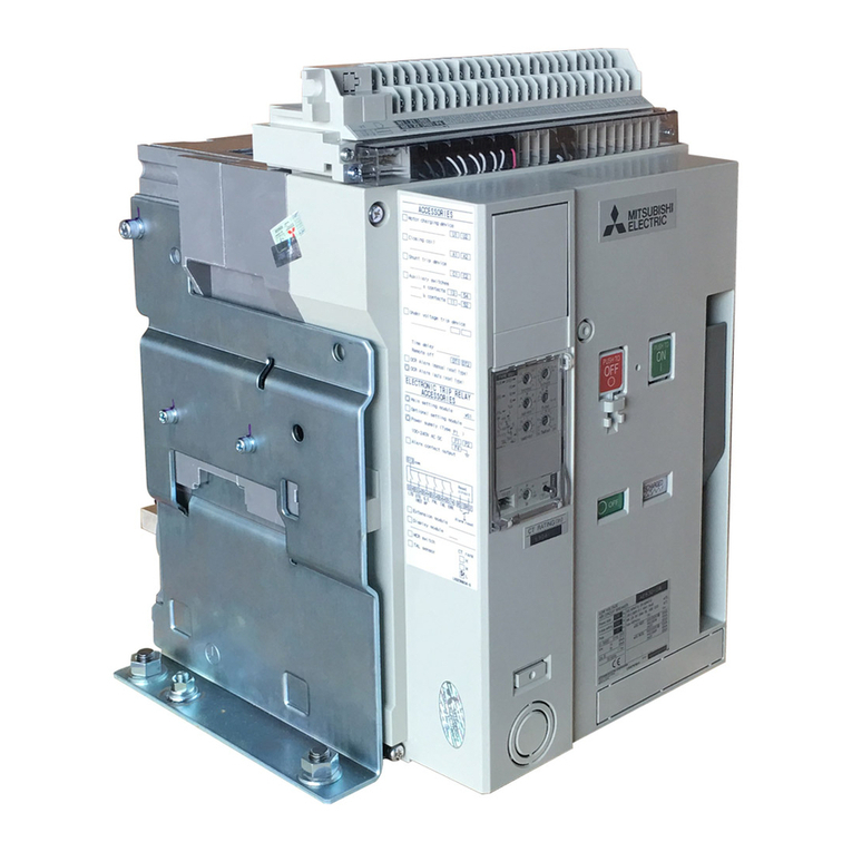
Product Features
7
3
6
Product Outline
2
1Mitsubishi ACB Direct Drive
2Rated Current (630, 1000, 1250, 1600 A)
3AE V Series C-class
Line up (630 to 1600 A)
Rated current (A)
630 1000 1250 1600
AE V Series
C-class AED630-CV
AED1000-CV AED1250- CV AED1600-CV
World Super AE V Series
AED1600-CV
The C-class has the solenoid mechanism inside its body.
Developed to meet customers’ expectation and needs. Breaking capacity (Ics = 100% Icu at 500 V AC)
Rated
current
Mitsubishi
AE-SW
Series
Mitsubishi
AE V Series
C-class
630 A
1000 A
1250 A
1600 A
65 kA 50 kA
Short time withstand current (Icw 1 s)
Rated
current
Mitsubishi
AE-SW
Series
Mitsubishi
AE V Series
C-class
630 A
1000 A
1250 A
1600 A
65 kA 50 kA
Mitsubishi Electric offers new air circuit breaker, AE V Series C-class.
It has the breaking capacity of 50 kA at 500 V AC and can provide with the
appropriate suggestion for the market with the breaking capacity of 50 kA or less.
Short time withstand current (Icw 3 s)
Rated
current
Mitsubishi
AE-SW
Series
Mitsubishi
AE V Series
C-class
630 A
1000 A
1250 A
1600 A
50 kA 36 kA
Specications of AE V Series C-class compared to AE-SW Series (Existing model)
World Super AE V Series C-class is
All New Mitsubishi Air Circuit Breaker series.
AE V Series C-class is certified by the following parties.
• China Compulsory Certificate system (CCC)
• Keuring van Elektrotechnische Materialen te Arnhem (KEMA)
Certicate
The adoption of the solenoid mechanism brings positive effects on the circuit breakers.
ACB (solenoid)
Control voltage
110-125 V AC
220-250 V AC
110-125 V DC
220-250 V DC
Solenoid mechanism
Solenoid mechanism is adopted to AE V Series
C-class for ON operation. So you don’t need to
purchase “Closing coil (CC)” and “Motor charging
device (MD)” additionally which are needed by
existing model.
You just purchase “Shunt trip device (SHT)” to
utilize remote control function easily in case of
AE V Series C-class. It can be used for switching
a power supply as well.
Remote operation
No need to use motor charging device. Direct
closing by Closing magnet. Charging noise is
extremely low compared to our existing spring
charge type ACB (AE-SW Series) and the impact
inside panel can be reduced when charging
operation.
Silent charging
Product FeaturesProduct Outline
1 2 3
Added Added Added

Product Features
Product Features
8 9
33
It is possible to choose the N pole position either
left or right side as needed by customers. The
default position of N pole is right side. Please
inform us before placing an order in case the N
pole on the left side is needed.
• Standard of N pole position is on the right
side unless otherwise instructed.
• N pole on the left side is specially made in
case of 4-pole model.
Left: N pole
(Special) Right: N pole
(Standard)
Flexibility of Neutral pole (N pole) (Only 4-poles model)
New Features
The ETR has the following types; “Without DP” and “With DP”.
Electronic trip relay (ETR) for AE V Series C-class
Long-time
Short-time
Instantaneous (with MCR)
Pre-alarm
Main protection
(as standard)
Ground fault (The control power supply is not required.)
Optional protection
(as option)
[P3] 100-240 V AC/100-125 V DC
with output contacts
[P4] 24-60 V DC with output contacts
[P3] 100-240 V AC/100-125 V DC
with output contacts
[P4] 24-60 V DC with output contacts
Power Supply
(Note 2)
Not available
Communication
– Current display on ETR as standard
Display
Basic protection without
display option
Basic protection with
current display
Type of ETR unit
(Note 1)
Without DP With DP
Note 1) The above ETR units aren’t modular structure.
Note 2) For details, refer to page 23.
SHT (Shunt trip device) is improved to “Permanent SHT without
controller” as standard. This makes OFF lock possible.
Permanent Shunt trip device (Permanent SHT)
New Features
AE V Series C-class is equipped with a built-in drawout handle as standard. Just insert a built-in drawout handle into
the body after using it.
Built-in drawout handle
New Features
Built-in drawout handle
UVT delay unit
The shape of
built-in drawout handle
UVT is newly designed. UVT controller is not needed for New ACB when operating
time of UVT is instantaneous.
Adding “UVT delay unit” enable UVT operating time 0.5 s,
1.5 s, and 3 s. (New UVT has operating time 1.5 s.)
New UVT (INST) is only coil unit
UVT (INST) without controller
New Features
Integrated
SHT
Breaker
Control
supply
Coil
C1
C2
Circuit for
locking the
breaker
OFF position
SHT circuit diagram

11
5
Closing method
10
Product Specication
4
Product Specication
Type AED630-CV AED1000-CV AED1250- CV AED1600- CV
Number of poles 3, 4
Rated insulation voltage (V) Ui 1000
Impulse withstand voltage (kV) Uimp 12
Rated operational voltage (V AC 50/60 Hz) Ue 500
Suitability for isolation IEC 60947-2 Yes
Pollution degree IEC 60664-1 3
Environmental condition for EMC IEC 60947-2 A
Circuit breaker as per IEC 60947-2
Rating of neutral pole (A) 630 1000 1250 1600
Sensor ratings (A) 630 1000 1250 1600
Rated current setting Ir (A)
at 40°C
General use
(Rated current adjustable)
0.5 to 1.0 × In, 0.05 step
315-346.5-378-
409.5-441-472.5-
504-535.5-567-
598.5-630
500-550-600-650-
700-750-800-850-
900-950-1000
625-687.5-750-
812.5-875-937.5-
1000-1062.5-1125 -
118 7. 5 -12 5 0
800-880-960-
1040-1120-1200-
1280-1360-1440-
1520 -1600
Utilization category B
Ultimate breaking capacity (kA rms)
50/60 Hz (Note 1) (Note 7) Icu 240-500 V AC 50
Rated service breaking capacity (kA rms) Ics % Icu 100%
Rated short-time withstand current (kA rms)
50/60 Hz Icw 1 s 50
3 s 36
Rated making capacity (kA peak)
50/60 Hz Icm 240-500 V AC 105
Breaking time between tripping order and arc extinction (ms) 40 (Note 2)
Closing time (ms) 300
Switch-disconnector as per IEC 60947-3 (Note 8)
Operational current AC-23A 630 1000 1250 1600
Rated making capacity (kA peak)
50/60 Hz Icm 240-500 V AC 52.5
Rated short-time withstand current (kA rms) Icw 1 s 50
3 s 36
Maintenance/Connection/Installation
Service life (Note 4)
Mechanical
with regular ordinary
maintenance prescribed by the
manufacturer
10000 (Note 3)
Electrical
with regular ordinary
maintenance
prescribed by the
manufacturer
240-500
V AC 6000
Connection (Note 5)
Horizontal Available
Vertical Available
Front Available
Dimensions (mm) (H × W × D)
Fixed 3-pole 410 × 340 × 290
4-pole 410 × 425 × 290
Drawout 3-pole 430 × 300 × 375
4-pole 430 × 385 × 375
Weight (kg) (without accessories)
(Note 6)
Fixed 3-pole 37
4-pole 43
Drawout 3-pole 57
4-pole 66
Reverse connection Possible
Note 1) The MCR is equipped as standard.
Note 2) This value indicates the operating time for the O operation at the time of short circuit interruption. (For the CO operation, the value is 135 ms.) For the product with a UVT, refer to page 16.
Note 3) The mechanical service life includes the electrical service life.
Note 4) This is a guide of the service life when the regular maintenance specified by the manufacturer is performed. Regular maintenance means inspection, grease lubrication, as-needed replacement of
prescribed component and so on.
Note 5) For the details on the connection method of terminals, refer to Available connections (on page 14).
Note 6) This weight indicates the weight of product with a electronic trip relay, which does not include other accessories. The values in the table are typical values and are not guaranteed values.
Note 7) When the breaker without a trip relay (BARE) and the external OCR for general purpose are used, the breaking capacity is 25 kA.
Note 8) AED-CV complying with IEC 60947-3 will be launched in 2021.
Closing method
The breaker closes electrically.
The following describes the closing methods.
1. The breaker closes by pressing the ON button.
2. The breaker closes electrically by remote operation
and opens by pressing the OFF button.
•The indicator shows the ON or OFF state of the main contacts.
•The breaker cannot be closed while the OFF button is being pressed. (Safety design)
•OFF lock is enabled by padlock (Refer to page 12, 20) as standard.
Solenoid mechanism
Note) The voltage is required to apply to the control circuit terminal block. The rated value and circuit diagram are shown below.
Note) In consideration of the voltage drop, set the power supply capacity for the solenoid not to be less than the operating voltage.
Rated voltage (V) Applicable
voltage range (V) Applied voltage (V) Current
(Peak value) (A) Operating time (s) Criterion for power
requirement
AC
(50/60 Hz)
110 - 12 5 93.5-137.5 110 6.5
≤ 0.3
1000 VA
125 7.7
220-250 187-275 220 3.3
250 3.9
DC
110 - 12 5 93.5-137.5 110 7.1
1000 W
125 8.4
220-250 187-275 220 3.5
250 4.2
ACB (solenoid) control rating
Breaker
Solenoid
coil
ON
button
Close to ON
(less than 10 m)
A2
S1
A1
S2
Solenoid
controller
Standard controller diagram

12 13
Appearance and Product structure
6 6
Appearance and Product structure
Arc chute chamber
ON button
Manual reset button
Cradle
Extension rail
Drawout position indicator
World Super AE V Series
AED1600-CV
World Super AE V Series
AED1600-CV
For the fixed type, lifting hooks (HP) are attached.
For the drawout type, a built-in drawout handle is attached.
ON/OFF indicator
Lifting hole
Lifting hole
Padlock hook
OFF button
Electronic trip relay
Control circuit terminal block
Aperture for the drawout handle
Position lock
Fixed type
Drawout type
1
Air circuit breaker
2
Cradle
3
ETR unit
4
Door frame (DF)
5
Dust cover (DUC)
6
Push button cover (BC-L)
7
Auxiliary switch
Standard (LAX)/Low capacity type (LVAX)
8
Shunt trip device (SHT)
9
Under voltage trip device (UVT)
AED630-CV
AED1000-CV
AED1250-CV
AED1600-CV
Type
1
Push button cover
Counter
Cylinder lock
Terminal cover
Door frame
Dust cover
Interphase barrier
Mechanical
accessories
6
Auxiliary switch
Shunt trip device
Under voltage trip device
Electrical
accessories
5
Cell switch
Shorting b contact
Lifting hook
Safety shutter
Safety shutter lock
Mis-insertion preventor
Test jumper
Drawout type
accessories
4
Fixed/Drawout type
Horizontal terminal (HT)
Vertical terminal (VT)
Front terminal (FT)
Connection
3
10
UVT delay unit
11
Counter (CNT)
12
Cylinder lock (CYL)
13
Safety shutter (SST)
14
Safety shutter lock (SST-Lock)
15
Cell switch (CL)
16
Interphase Barrier (BA)
17
Universal terminal (HT/VT)
18
Front terminal (FT)
IEC 60947-2
IEC 60947-3 (Note)
EN 60947-2
GB/ T 14048.2
GB/ T 14048.3
Standard
2
General use
VS type with MCR switch
Optional
GF: Ground fault protection
DP: Display
Neutral CT
Electronic trip relay
7
Skeleton
Product conguration
3
5
6
7
12
11
12
10
9
8
4
15 16
17
18
13 14
Note) AED-CV complying with IEC 60947-3 will be launched in 2021.

15
8
Accessories
14
Connections
7
Horizontal (HT) Vertical (VT) Front (FT)
Fixed type
(FIX)
Drawout type
(DR)
Connections
Type Connections
• Connection image: AED630-CV to AED1600-CV, 3-pole type
FIX-HT FIX-VT FIX-FT
DR-HT DR-VT DR-FT
Overview (AED630-CV to AED1600-CV)
Type LINE (upper) side/LOAD (lower) side Abbreviation AED630-CV/AED1000-CV/AED1250-CV/AED1600-CV
Fixed type
(FIX)
Horizontal/Horizontal FIX-HT
Available
Vertical/Vertical FIX-VT
Front/Front FIX-FT
Horizontal/Vertical FIX (HV)
Horizontal/Front FIX (HF)
Vertical/Horizontal FIX (VH)
Vertical/Front FIX (VF)
Front/Horizontal FIX (FH)
Front/Vertical FIX (FV)
Drawout type
(DR)
Horizontal/Horizontal DR-HT
Vertical/Vertical DR-VT
Front/Front DR-FT
Horizontal/Vertical DR (HV)
Horizontal/Front DR (HF)
Vertical/Horizontal DR (VH)
Vertical/Front DR (VF)
Front/Horizontal DR (FH)
Front/Vertical DR (FV)
Available connections
The shunt trip device is a device to open the breaker by remote control.
Shunt trip device (SHT)
1
Note 1) While the voltage is applied to the input terminals (C1 and C2), the SHT keeps the
breaker in the open state and the closing operation is cancelled. Therefore, the SHT can
be used as an interlock for locking the breaker in the open state.
Note 2) In case of double rating of rated voltage, it is the value for the lower rating. (Example) In
case of 24-30 V DC, it is operating time for 24 V DC.
Diode rectifier is not used for control source 24-30 V DC and
48-60 V DC.
Accessories
2
3
1
4
6
5
SHT
Breaker
Control
supply
Coil
C1
C2
Circuit for
locking the
breaker
OFF position
SHT circuit diagram
Option
Under voltage trip device
OCR alarm
Shunt trip device
Auxiliary switch
Standard/Low capacity type
Counter
Cylinder lock
For breaker unit
Rated voltage
(Applicable
voltage)
Frequency
(AC)
Steady power
consumption
(Note 1)
Operating
time
(Note 2)
Operating
voltage
24-30 V DC
(16.8-33 V)
–
24 V 4 A 100 W
20 VA 0.05 s
max.
30 V 5 A 150 W
48-60 V DC
(33.6- 66 V)
48 V 2.5 A 120 W
60 V 3 A 180 W
100-125 V AC/DC
( 70 - 137. 5 V )
50/60 Hz
100 V 1 A 100 VA
125 V 1.2 A 150 VA
200-250 V AC/DC
(140-275 V)
200 V 1 A 200 VA
250 V 1.1 A 280 VA
Inrush current and
power consumption

16 17
Accessories
8 8
Accessories
Trip button
Power supply
2 m max.
UVT
UVT
Coil
D1
D2
DT1
DT2
Circuit for voltage
monitoring and
coil energization
Breaker
UVT delay unit
OFF function circuit
UVT circuit diagram
This is the device that automatically trips the breaker when the circuit voltage
drops below the nominal voltage.
There are 4 kinds of tripping time, INST, 0.5 s, 1.5 s, and 3 s. A trip terminal for forced
OFF function is included as standard equipment.
Under voltage trip device (UVT)
2
Rated voltage
(Applicable voltage)
Frequency
(AC)
Operating time
(Time delay)
Pick-up
voltage
Drop-out
voltage
Inrush current and power consumption
Steady power
consumption
Operating voltage
48 V DC
(52.8 V max.)
–INST (0.3 s max.)
0.5 s or more
1.5 s or more
3 s or more
(Note 1)
(Note 2)
(Note 3)
31. 2- 4 0. 8 V 21.6-33.6 V 48 V 3 A 150 W
20 VA
100-120 V AC/DC
(132 V max.)
50/60 Hz
65-85 V 45-70 V 100 V 2 A 200 VA
120 V 2.4 A 300 VA
200-240 V AC/DC
(264 V max.)
13 0 -17 0 V 90 -140 V 200 V 1 A 200 VA
240 V 1.1 A 280 VA
Note 1) The UVT delay unit is built in the products with the operating time 0.5 s, 1.5 s, or 3 s. (The UVT delay unit requires 30 seconds to charge. The
operating time shortens if the voltage becomes insufficient within 30 seconds after the voltage is started applying to UVT.)
Note 2) The operating time is a guarantee value when it drops from 85% or more of rated voltage.
Note 3) Time delay should be allowed for 0.5 s between applying the voltage to the UVT and closing the breaker.
Note 4) If a remote trip function is required, remove the shorting bar (DT1, DT2) and connect a normally closed switch, rated 10 mA at 30 V DC (Min.
applicable load 15 V DC 1 mA or less) across them.
Note 5) If a forced OFF function is used, the shorting (signal input to DT1 and DT2) should be held for 0.3 second or more.
(Note 4)
(Note 5)
Option
•The a and b contacts may simultaneously be turned ON instantaneously at the time of switching
contact; Pay attention to the contact state when designing circuits.
•The chattering time at the time of contact ON-OFF is below 0.025 s.
Voltage (V)
Current (A)
Standard (LAX) Low capacity type (LVAX)
Resistive
load
Inductive
load
Resistive
load
Inductive
load
AC
(50/60 HZ)
250 3 2 – –
125 5 3 0.1 –
DC
250 0.2 0.2 – –
125 0.4 0.4 – –
30 4 3 0.1 –
Contacts max. 5a5b 5a5b
Change-over
sequence
Breaker state a contact (NO) b contact (NC)
ON ON OFF
OFF OFF ON
This is the contact that remotely indicates the ON or OFF status of the breaker.
Auxiliary switch
Standard (LAX) / Low capacity type (LVAX)
4
AC: DC
125
100
60
30
Current (mA)
Voltage (V)
10
5
0.67 1 4 26 50
•LAX (Standard)
• OCR alarm (AL)
AC
100 160 600
DC
Switch rating Min. load range graph
Option
The door frame improves the appearance, after cutting out the panel door
to install the breaker.
As for panel cut-out dimensions, refer to page 34.
Door frame (DF)
Option
The cover prevents careless manual operation (ON, OFF) of the push buttons.
BC-L can be locked by a padlock. (The padlock should be supplied by the customer.)
For the suitable size of a padlock, refer to page 20.
Push button cover (BC-L)
Option
The breaker is locked in the OFF state with the cylinder lock.
•Since it is an interlock which only allows the key to be removed when the breaker is locked off,
it can be used for interlocking two or more breakers.
•Up to 5 types of cylinder locks can be manufactured. Consult us for details.
Cylinder lock (CYL)
5Option
The number of switching operations of the breaker are shown by a 5
digit counter.
Counter (CNT)
6Option
The gray manual reset button on the front side of the breaker will stick out
continuously to the output OCR alarm (AL) if the breaker is tripped by the electronic trip
relay. After tripping, the breaker can not be turned ON unless the manual reset button is
pressed for resetting.
OCR alarm (AL) [MRE: Manual reset type]
3
Standard *
Note 1) This works when tripping occurs in LTD, STD, INST or GF.
Note 2) The alarm continues to output until the manual reset button is pressed.
98
OCR alarm switch
97
Voltage (V)
Current (A)
Resistive load Inductive load
AC
(50/60 Hz)
240 3 2
125 5 3
DC
240 0.2 0.2
125 0.4 0.4
30 4 3
Switch rating
*Standard if ETR is equipped.
AL in operation
UVT delay unit
(Note 1)

18 19
Accessories
8 8
Accessories
12
3
4
Cell switch
Shorting b contact (Rear side)
Safety shutter
Safety shutter lock
This is the switch to show the drawout position (CONNECTED, TEST, and
DISCONNECTED) of the breaker. An arbitrary combination up to 4 pieces is available.
Cell switch (CL)
Option
Voltage (V)
Current (A)
Resistive load Inductive load
AC
(50/60 Hz)
250 10 10
125
DC
250 31.5
125 10 6
30 10 10
Contacts max. Total 4c max.
Switch rating
Standard pattern
Operating sequence
Drawout position of breaker Disconnected Connected
Display position of
drawout operation
TEST CONNECT
CL-C
(CONNECTED)
CL-T
(TEST)
CL-D
(DISCONNECTED)
Switch function
Change-over sequence
(a contact)
OFF
OFF
OFF
ON
ON
ON
Note) The setting can be changed by customers later.
A preliminary setting of CL at factory shipment is as follows.
CL1: 1C, CL2: 1C1D, CL3: 1C1T1D, CL4: 2C1T1D
CL-C CL-T CL-D
CL1 1 – –
CL2 1 – 1
CL3 111
CL4 2 1 1
1
5Mis-insertion preventor
For drawout type
When moving the breaker from the connected position to the test positions,
this contact is used to short-circuit the auxiliary switch (LAXb), thus maintaining the
correct sequence of operation of the external control circuit. When ordering, SBC with
the same number of contacts as auxiliary switches (LAXb) will be provided. Up to 5
SBCs can be mounted.
Shorting b contact (SBC)
Option
Operating sequence
Main circuit Disconnected Connected
Display position of
drawout operation
TEST CONNECT
Change-over sequence
of SBC
(b contact)
ON
OFF
2
This device enhances the interphase insulation between the terminals of the
breaker, and prevents short-circuit due to conductive objects or dust.
It can be attached and detached easily. The interphase insulation is available for all
connection methods.
Interphase barrier (BA)
Option
The transparent terminal cover prevents users from careless touching to the
live control terminals.
International Protection is IP20 (IEC 60947-1 Annex C). The terminal cover is available
for both the fixed type breakers and the drawout type breakers.
Terminal cover (TTC)
Option
The dust cover prevents the dust or water from entering into the panel board
due to the breaker panel cut.
Protection degree is IP54. DUC can be locked by the padlock. (The padlock should be
supplied by the customer.) For the suitable size of the padlock, refer to page 20. Consult
us for details.
Dust cover (DUC)
Option
DISCONNECT
DISCONNECT

20 21
Accessories
8 8
Accessories
This device prevents other breakers unspecified from inserting into the cradle,
and 5 patterns in maximum are available.
Mis-insertion preventor (MIP)
Option
5
This is the safety device that prevents insertion and drawout operation. When the breaker is ON,
the drawout handle cannot be inserted, and insertion and drawout operation cannot be done unless the OFF
button is pressed.
Drawout interlock
This is the device that locks automatically the drawout mechanism
at “TEST” or “CONNECT” positions during insertion and drawout operation. When the
lock plate is pushed in, lock is released and operation can be continued.
Position lock
A padlock can be arranged at the lock plate. Thereby, it is possible to prevent the
connection position from being changed unnecessarily.
As for outline dimensions of the padlock, please refer to the left figure.
Note 1) For the breaker, only the padlock with ø 5 is available. For the BC-L, Position lock, and SST-Lock, DUC the padlock with ø 5 or ø 6 is available.
Note 2) The padlock is available for the push button cover, safety shutter lock, and position lock.
Outline dimensions (reference)
Padlock
ø5 or ø
6
35 or 40 (mm)
This is the metal fitting to suspend the main body when the breaker is
removed from the drawout cradle. The fixed type breaker is equipped with HP as
standard.
Lifting hook (HP)
Option
With the breaker taken out of its cradle, this device enables the breaker to be
electrically opened and closed, and the operating sequence to be checked. A cable of 3 m
is equipped as standard shipment.
An extension cable (5 m) is providable.
Test jumper (TJ)
Option
Both the main and control circuits
are connected.
Normal in use condition.
The lock plate is protruding.
The main circuit is disconnected,
but the control circuit is connected.
The breaker operation can be
tested with the door closed.
The lock plate is protruding.
Both the main and control circuits
are disconnected.
The door can be closed.
This is the position for removing
the breaker.
The breaker is drawn out of the
cradle on the extension rails.
CONNECTED position TEST position DISCONNECTED position DRAWOUT position
Operating position of drawout type
The safety shutters cover the conductors (cradle side) and prevent contact
with them when the breaker is drawn out.
Safety shutter (SST)
3Option
This kit is used to lock the safety shutters using a padlock (the padlock to be
customer’s supply). The safety shutters close when the breakers are drawn out to
prevent accidental contact with the main contacts.
This kit is used for the safety shutters both in the line side and load side.
The safety shutter is locked while the breaker is open, and is unlocked automatically by
inserting the breaker.
Safety shutter lock (SST-Lock)
4Option
Standard *
Standard *
*Standard equipment in case of Drawout type

22 23
Electronic trip relay
9 9
Electronic trip relay
Power supply option
It provides the control power source for the trip
indicator LED and DP.
Please select a Power supply type from P3 or P4,
which include Power supplys with output contact. (The
overcurrent protection and ground fault protection
(GF)* can work with power from the internal CT,
even if the control power source is off.)
Main setting
The characteristic setting function of the overcurrent
protection according to application can be set.
ETR for general use (Type: S1) has the setting dials
for LTD, STD, and INST operating characteristics.
The 4-pole breaker provides the neutral 100%
protection as standard.
Optional setting option
Ground fault protection (GF) can be added as needed.
GF: Ground fault protection
ADisplay option
The measuring data (current) and alarms can be displayed
with this module.
B RUN and ERR. LED standard
This indicator displays the ETR situation (Run or Error).
CLoad current LED standard
This indicator shows the actual current-carrying level.
The LED of 60, 80, 100, or OVER lights. When the load
current exceeds 60% of Iu, the LED of 60 lights. When the
load current exceeds the pickup current of LTD, the LED
of OVER lights, and the breaker will be tripped after the
predetermined time.
D Pre-alarm (PAL LED and Current setting dial) standard
This indicator displays the Pre-alarm situation when the
setting current is exceeded.
ETrip indicator LED standard
This indicator displays the trip cause. (Self-holding type)
If the output contact for this trip indicator is required, The
power supply module should be selected from P3 or P4.
FTEST terminal standard
This TEST terminal is used for the field testing of characteristics
with Mitsubishi Tester “Y-2005” (refer to page 27).
GRESET button standard
With this RESET button, trip indicator, display data such as
a fault cause and fault current and Pre-alarm are reseted.
When the power supply module P3 or P4 is equipped, the
resetting from the control circuit terminal becomes possible.
Additionally, this RESET button provides a lock function
of LTD and STD characteristics on the INST testing with
Mitsubishi Tester “Y-2005”.
OCR alarm (AL) standard
When the breaker is tripped by the overcurrent or ground fault
protection (GF), this device continuously outputs the alarm
signal until the alarm is reset. For details, refer to page 16.
Neutral pole overcurrent protection (NP) standard
When the humanics in load current become higher, the
current on the neutral pole may exceed the rated current.
This Neutral pole overcurrent protection prevents the
troubles caused by higher Harmonics.
Note *) For Ground fault protection, it works under the rated current (In) setting of 0.2-1.0
without Control power source.
Note) When using an ETR with DP, select the power supply type.
A
B
C
D
E
F
G
Feature
Note 1) The overcurrent protection and ground fault protection operates without control power source.
Note 2) Factory setting of 5 output contacts is as follows.
Power supply module
Type of Electronic trip relay
Type: VS1 –
Optional function
NA: Without optional setting
GF: Ground fault protection
DP: Display
DPGF: Display & Ground fault protection
VS1DPGFVS1DPVS1GFVS1NA
Power supply
P3: 100-240 V AC/100-125 V DC
with output contact
P4: 24-60 V DC with output contact
Type Rated voltage (V) Applicable voltage range (V) Criterion for
power requirement (VA) Alarm output
P3 100-240 AC (50/60 Hz)/
100-125 DC
85-264 AC
85 -138 DC 15 5 output contacts
P4 24-60 DC 18-72 DC 10 5 output contacts
Voltage (V)
Current (A)
Resistive load Inductive load
cosØ= 1.0 cosØ= 0.4
L/R = 0.7
AC
(50/60 Hz)
240 10.5
120 1 1
DC
125 0.1 0.05
30 1 1
Contact capacity (Type P3 and P4)
1LTD 2STD/INST 3GF 4PAL 5ERR.
Self-holding Self-holding Refer to lower table Automatic reset Automatic reset
Self-holding: The output is maintained until it resets.
Automatic reset: The output will be reset if it backs to normal condition.
ETR dial set GF
TRIP side Self-holding
ALARM side Automatic reset

5000
4000
3000
2000
1000
500
400
300
200
100
60
50
40
30
20
Operating time (s)
Current (%)
(s)
(min)
(h)
10
5
4
3
2
1
.5
.05
.04
.03
.02
.01
.4
.3
.2
.1
1
2
10
15
30
40
1
20
8
6
4
50
40
30
20
10
5
4
3
2
1
.5
.05
.06
.04
.03
.02
.01
.4
.3
.2
.1
1 2 5 10 20 50
100 125 150
200 500 1000 1600 2000 5000 10000
INST/MCR pick-up current: Ii
Ir × 2-4-6-8-10-12-16 ±15%
Max. breaking time (Note 3)
I2t OFF
I2t ON
(ramp)
With MCR
STD time: Tsd (Note 1) (Note 2)
0.06-0.1-0.2-0.3-0.4-0.5 (s) ± 20%
(at Isd × 1.5)
Ir × 0.8-1.0 (step 0.02)
Uninterrupted current: Iu
LTD pick-up 1.05 × Iu…Non pick-up
1.25 × Iu…Pick-up
STD pick-up current: Isd
Ir × 1.5-2-2.5-3-4-5-6-7-8-9-10 ±15%
Pre-alarm time: Tp
TL/2 ± 20% (at Iu × 2)
Pre-alarm current: Ip
Iu × 0.68-1.0 (step 0.04) - OVER ±10%
LTD time: TL
12-25-50-100-150 (s) ± 20%
(at Iu × 2)
24 25
Electronic trip relay
9 9
Electronic trip relay
No. Setting item Mark Adjustable setting range Accuracy Factory default
value
ACurrent setting Ir 0.5-1.0 (step 0.05) × In (CT rating) – 1.0
KUninterrupted current Iu 0.8-1.0 × Ir (step 0.02), Pick-up current: 1.15 × Iu 1.05 × Iu…Non Pick-up
1.25 × Iu…Pick-up 1.0
LLTD time TL12-25-50-100-150 s at Iu × 2 ±20% 150
MSTD pick-up current Isd 1.5-2-2.5-3-4-5-6-7-8-9-10 × Ir ±15% 10
NSTD time Tsd ±20%
(Note) 0.5 (I2t ON)
JINST/MCR
pick-up current Ii ±15% 16 (INST)
GPre-alarm current Ip Iu × 0.68-1.0 (step 0.04) -OVER ±10% OVER
–Pre-alarm time Tp 1/2 TLat Iu × 2 (after 1/2 TL, PAL contact output turns on.) ±20% –
Adjustable setting range
Note) The figure shows ETR type: VS1DPGF.
Display and Ground fault protection are optional equipments.
In (CT rating) Ir
Ig ( P. 2 6 )
Iu
Isd
Ii
Ip
Load current LED
(60, 80, 100%, OVER)
Relation of setting dial
The table and the figure include both optional display.
Pre-alarm current “OVER” setting is Iu × 1.15.
Note) (O operation) When Tsd = “0.06” setting, operating time is 0.04-0.1 s.
When Tsd = “0.1” setting, operating time is 0.1 s ±50%.
(CO operation) When Tsd = “0.06, 0.1” setting, operating time is 0.04-0.15 s.
16-12-10-8-6-4-2-2-4-6-8-10-12-16 × Ir
(INST) (MCR)
Current setting dial
A
INST/MCR pick-up current setting dial J
Load current LED
B
Uninterrupted current setting dial K
RUN LED
C
LTD time setting dial L
ERR. LED
D
STD pick-up current setting dial M
Pre-alarm LED
E
STD time setting dial N
Trip indicator LED
F
Ground fault protection setting module dial O
Pre-alarm current setting dial
G
TEST terminal
I
Frequency setting switch
H
RESET button (TEST L/S LOCK button) P
For general purpose: Type S1
0.5-0.4-0.3-0.2-0.1-0.06-0.06-0.1-0.2-0.3-0.4-0.5 s
(I2t ON) (I2t OFF)
at Isd × 1.5
Operating characteristic curve (for general purpose: Type S1)
Current LTD pick-up, Ip …% of Uninterrupted current Iu
Iu, Isd, Ii ………… % of Current setting Ir
Note 1) (O operation) When Tsd = “0.06” setting, operating time is 0.04-0.1 s.
When Tsd = “0.1” setting, operating time is 0.1 s ±50%.
(CO operation) When Tsd = “0.06, 0.1” setting, operating time is 0.04-0.15 s.
Note 2) I2t is selectable: ON or OFF.
Note 3) When CO operation, max. breaking time is 0.135 s.

26 27
Electronic trip relay
9 9
Electronic trip relay
The display shows the current and harmonics for real time monitoring.
Moreover, the fault memory function is available so that it is possible to find out the
reason of breaker trip.
Display (DP)
Option
ETR
ACB
Power
supply
Alarm
contact
output
513
544
P1
P2
N1
N2
NCT
Block diagram with NCT function
The Neutral CT is used for ground fault protection when the 3-pole breaker is
used on a 3-phase 4-wire system and for the overcurrent protection on N phase.
Please use this CT in combination with ground fault protection (GF).
As for the outline dimensions, refer to page 34.
The length of the cable (attached) for NCT is 2 m.
Neutral CT (NCT) *Only use for AE V Series
Option
GF function block diagram (In case of 4-pole breaker)
ETR
ACB
Power
supply
Alarm
contact
output
513
544
P1
P2
60
50
40
30
20
Operating time (s)
Ground fault current (% of CT rating ln)
0.1
0.3
3.0
0.1 1.0
(s)
10
5
4
3
2
1
.5
.05
.04
.03
.02
.4
.3
.2
.1
1
50
40
30
20
10
5
4
3
2
1
.5
.05
.04
.03
.02
.4
.3
.2
.1
10 20 50
100 125150
200 500 1000
Ground fault pick-up current: lg
In × 0.1-1.0 ±20% (step 0.1)
Ground fault time: Tg (Note)
0.1-0.15-0.3-0.5-0.8-1.5-3.0 (s) ±20%
Ground fault protection characteristic curve
Type name ACB type Rating ampere of current transformer (A)
NCT-06-V AED630-CV 630
NCT-10-V AED1000-CV 1000
NCT-12-V AED1250 - CV 1250
NCT-16-V AED1600-CV 1600
Neutral Current Transformer type name
For outline dimensions, please refer to page 34.
Note) When Tg = “0.1” setting, operating time is 0.1 s ±50%.
When Tg = “0.15” setting, operating time is 0.15 s ±30%.
Specications of display indication
Measuring items Measuring
range Display indication Remark
Current
(A)
Current of each phase 0 to 200% In ***** A (In = 630 A to 1600 A)
Indication of 1 to N phase concurrently
(Bar graph display is also available)
Maximum value –
Harmonics
(HI)
Fundamental harmonics of each phase
0 to 100% In
***** A (In = 630 A to 1600 A)
Indication of 1 to N phase
Harmonics of each phase/degree (3rd, 5th, 7th, 9th)
Each phase total value
Each phase total distortion rate ***.* %
Content rate of each phase/degree
Fault
memory
Trip cause/Fault current 0 to 2000% In
LTD
STD
INST
***** A (0-19999 A)
–
***.* kA (20000 A and more)
0 to 200% In GF ***** A GF is an option
Elapsed time since tripping 0 to 24:00 h: m Time is recorded up to 24 hours
Optional function for electronic trip relay
The electronic trip relay can be checked by this field test device when the
breaker is at the test position or the disconnect position. The breaker will be tripped
when tested with this device in the “trip mode”.
Field test device (Y-2005)
Option
Test items LTD, STD, INST, GF, PAL
Range of signal output Voltage signal equivalent to 1% to 2500% of Rated current In (CT rating)
Dimensions 220 mm (W) × 150 mm (H) × 340 mm (D)
Time counter 0.000 to 999.999 s
Input voltage 100-240 V AC 50/60 Hz
Weight 4.5 kg
Y-2005 specication
Example of display indication
Time after tripping
“HH:MM”
Bar graph display
current (A)
Current (A) Harmonics (HI)
Maximum current (A)
Trip cause
Fault current
Time after tripping
Trip cause
With this MCR switch, at the time of breaker closing from OFF to ON the INST (Instantaneous)
characteristic works, and then after breaker is in closed (ON) position the INST characteristic becomes ineffective.
This controlling function of INST characteristic is useful for the protection on the short-circuit fault at the time of
closing and also for expanding the selective combination with branch breakers after closed.
MCR is equipped as standard.
MCR
Standard
The ground fault protection (GF) of several hundred amperes is available.
This function can be selected for trip or alarm (no trip). Power supply is necessary
for this function, even if there is not power supply, it can function at 0.2 × In or higher.
Ground fault protection (GF)
Option
Setting item Mark Adjustable setting range Accuracy Factory default value
GF pick-up current Ig 0.1-0.2-0.3-0.4-0.5-0.6-0.7-0.8-0.9-1.0 × In ±20% 1.0
GF time Tg ±20%
(Note) 3 s (TRIP)
Alarm output –Setting for TRIP: Self-holding/Setting for ALARM: Automatic reset ‒Setting for TRIP (Self-holding)
3-1.5-0.8-0.5-0.3-0.15-<0.1 - <0.1-0.15-0.3-0.5-0.8-1.5-3 s
TRIP ALARM
Note) When Tg = “0.1” setting, operating time is 0.1 s ±50%.
When Tg = “0.15” setting, operating time is 0.15 s ±30%.
(at 1.5 × Ig)
Trip cause
INST
: Short circuit current trip.
STD : Large current in short time STD range.
LTD : Overcurrent in LTD range.
GF : Ground fault protection. (Option)

28 29
Electronic trip relay
9 9
Electronic trip relay
Electronic trip relay circuit diagram for general use
Power supply CT
Energy is supplied for the operation of the overcurrent
tripping and ground fault tripping (GF) function of
the electronic trip relay.
Power supply circuit
This part converts power supply CT energy to constant
voltage for respective circuits in the ETR.
Current sensor coil
The current in each phase flowing through the breaker
is detected. An air core coil which has good linearity
is adopted.
Micro controller
The Micro controller integrates each phase current
waveform from the Current sensor coil and performs
processing for overcurrent protection and others.
LEDs
The load current LED gives a figure of current in
percent by CT energy. Trip indicator and pre-alarm
are indicated by control power supply. RUN and
ERR. LED indicate breaker’s condition by control
power supply or ten-odd percent of CT energy.
Characteristic setting
This setting provides the characteristic setting of
the ETR.
Characteristic setting
Trip coil
Power supply CT
Current sensor coil
Electronic trip relay
Upper terminal
0V
0V
Trip indicator
TI LED
V+
Lower terminal
PAL pick-up LED
V+1
V+1
0V
N
Load current LED
60-80-100-OVER
Trigger
circuit
Micro controller
Setting input
W.D.T.
A/D
LTD
S/W
STD
S/W
INST
S/W
GF
S/W
Overload
/PAL
S/W
CPU
PAL
LTD
GF
STD/INST
I/O
Control power
circuit
RESET
CIRCUIT
Integration circuit
Power supply
circuit
Rectifier
circuit
N1
N2
+
−
513
554
524
534
544
RS1
P1
P2
P4
RS2
NCT input
Test
connector
1
1 5
6
7
2
3
4
2
Trip indicator
This outputs contact signals of fault cause (including
pre-alarm) and an other alarms.
A control supply is necessary for this function.
Setting procedure
1. Prepare a small flat tipped screwdriver.
2. Insert the flat tipped screwdriver into the opening of the ETR
cover.
Then, lightly turn the screwdriver to the upside as shown in
the left figure, and the ETR cover will open.
3. There are two kinds of switches for characteristics setting
and for trip indicator reset. They should be used as follows.
1Adjustable in steps
Rotary code switch is used. Do not set the switch at points
between steps. The setting value is the same when the
switch is positioned at the thick line. (Set the switch with a
torque of 0.02 N·m or below.)
2Push button
This is for temporary operation, and press it with force of
3N or less.
4. For ETR with Display, there is a slide type switch (Frequency
selector switch) as the left side picture shows.
1Frequency selector switch
Do not set the switch at points between the slide.
When operating the switch, use a flat tipped screwdriver
of the following size.
5. When the characteristic is set up, use a device like a field
test device, etc to make sure that the required characteristic
has been set.
6. When sealing, seal the ETR cover by using the sealing hole
at the top of the ETR cover.
Push the screwdriver into the direction
of the arrow to open the ETR cover
ETR cover
Operating hole for resetting
Sealing hole
1Adjustable in steps
1Frequency selector switch
(50 Hz/60 Hz)
In the case of ETR with Display
2Push button
Sealing hole
6 mm max.0.8 mm max.
Side view of the flat tip
3 mm max.0.8 mm max.
Side view of the flat tip
Note) For the N pole, the above diagram shows the (Standard) case that the accessories are equipped on the right side.
Note) If the switch is set at points between steps, the characteristics setting
value will be decided at either end of steps.
3
4
5
6
7

C2 51
DT1DT2
A2S297524534544554574P4N2N1
52 54 44 34 24 1442 32 22 12C1D1D2A1S1P2P1
L1
Power supply CT
and Current
sensor CT
Breaker
Main
circuit
P.22 P.23 P.16 P.17 P.17 P.19P.11,15,16
Electronic trip
relay (ETR)
Control power circuit/
alarm contact
Electronic operation
circuit
Auxiliary switch
(normal close)
Auxiliary switch
(normal open) Cell switch
OCR
alarm
Voltage forbid
to be applied
NCT
ERR.
PAL
GF
STD/INST
LTD
OFF
ON
Dielectric test forbidden
Electronic trip
relay (ETR)
Reset circuit Power circuit
Close to ON
(less than 10 m)
Close to reset alarm
(less than 2 m)
Power supply
Common
RESET
Power supply
Solenoid
Controller
ACB ON button
Tr i p
Circuit
AL
LAX
LAX SBC
SBC
SBC
SBC
SBC
LAX
LAX
LAX
LAX
LAX
LAX
LAX
LAX
FG Short
bar
Open to trip
(less than 2 m)
Cell switch
L2 L3 N
513 98
341
CL4
331
CL3
321
CL2
311
CL1
344 342 334 332 322324 312314
OFF
ON
41 31 21 11 53 43 33 23 13
SHTUVT
RS2RS1
30 31
Wiring diagram
10 10
Wiring diagram
The following diagram shows the case that accessories are fully equipped. For the N pole, the following diagram
shows the (Standard) case that the accessories are equipped on the right side.
Wiring diagram
13 14 ~ 53 54 Auxiliary switch “a contacts”
11 12 ~ 51 52 Auxiliary switch “b contacts”
D1 D2 Voltage Input terminal of UVT
DT1 DT2 Trip terminal of UVT (Remote trip)
A1 A2 Power supply for Solenoid Controller
S1 S2 External ON (Close by remote control)
C1 C2 Shunt trip
97 98 OCR alarm
P1 P2 Power supply for ETR
P4 FG of power supply (FG: Frame Ground)
RS1 RS2 Alarm reset (Trip cause, alarm contact)
513 , 524 , 534 , 544 , 554 , 574 Trip cause, alarm contact
N1 N2 For Neutral CT (NCT)
SHT
Shunt tripping device
UVT
UVT coil
LAX Auxiliary switch Standard
AL OCR alarm switch
SBC Shorting b contact
CL Cell switch
Terminal description Accessory Symbols
Internal wiring
External wiring (userʼs wiring)
Control circuit connector (drawout type)
• On the drawout type, the cables should have the length which allow the control circuit terminal block to be moved to the left or
right by 5 mm.
• When a coil load is connected in the same control circuit as the ETR, surge absorbers are required to absorb the surge voltage.
• Since some terminals are polarized, the wiring should be done correctly as the polarity shown in the wiring diagram when the
control voltage is DC.
• To close the circuit breaker remotely, connect a switch between terminals S1 and S2 .
The switch used for remote close should be rated 30 V DC 10 mA or more (minimum applicable load 15 V DC 1 mA or less).
• For the power supply type P3 or P4, the high sensitive relay used in contact output may cause the chattering noise (wrong output
of 1 ms level) during ON and OFF operation, depending on the panel placing condition. When it used in the quick responsive
sequence, the filter circuit of a few milli-second (ms) should be provided or the double reading sampling should be implemented.
• Alarm reset (Terminal: RS1 and RS2 ) and Alarm contacts (Terminal: 513 , 524 , 534 , 544 , 554 , 574 ) are available only
for power supply type P3, P4. The switch used for remote reset should be rated at 15 V DC 10 mA or more. Alarms will be reset
if terminals RS1 and RS2 are short-circuited for 0.5 seconds or longer.
• Under voltage trip device (UVT)
The switch used for remote trip should be rated 30 V DC 10 mA or more (minimum applicable load 15 V DC 1 mA or less).
Remote trip terminal has short bar at shipment, so remove it before using this function.
Disconnect the voltage input wires during dielectric testing of main circuit.
Applying power to the terminals A1 and A2 changes the terminals S1 and S2 to the live part. Applying power to the terminals
D1 and D2 changes a terminals DT1 and DT2 to the live part. Do not touch the terminals.

(mm)
Front view
Rear view
Side view
Rear view
Front view Side view
Dimention table
Condition A
Before BA installation
46.5
After BA installation
19
32 33
Outline dimensions
11 11
Outline dimensions
Outline dimensions
Drawout type AED630-CV, AED1000-CV, AED1250-CV, AED1600-CV
2 × Ø13
Connecting area
50
25
15
38
75
61
242
23
40
223
56
443164
106 67
8
15
6
67125145.5
28
23
15
8
461.5
40
61
103
375452
25
55 *220
373
172
23
283
35
54
370
220
92
A
224
15
15
340
430
17
15
Fully drawout
position Inside of the panel
(thickness 1.5-3.2)
Earth terminal
M8 screw
Disconnected
Test
Lifting hook hole
Interphase barrier
(removable)
Front face of control terminal
Panel
42.5
40
234149
298
*200
150 235
300
3P 4P
228
Control circut
terminal block
(M3.5 screw)
Operating panel center
Aperture for the
drawout handle
Neutral pole
Hole for fixing the
drawout frame
4 × Ø14
170 255
227
142
*
156
*
241
228
275
284
*
312
340
3P 4P
Neutral pole
Control circut
terminal block
(M3.5 screw)
Operating panel center
Earth terminal
M8 screw
(Left side)
Hole for fixing
the body
4 ×
Ø
14
Fixed type AED630-CV, AED1000-CV, AED1250-CV, AED1600-CV
*: Mounting pitch *: Mounting pitch
Note) The product can be installed with the N pole on the opposite side if specified. Note) The product can be installed with the N pole on the opposite side if specified.
Neutral
pole
right
(standard)
4P 3P
85 85
Operating panel center
85
50
Outline
of breaker
Operating panel center
Neutral
pole
right
(standard)
85 85 85
50
4P 3P
Outline
of breaker
Operating panel center
8585 85
50
4P 3P
Neutral pole
left (option)
Outline
of breaker
Operating panel center
85 85 85
50
4P 3P
Outline
of breaker
Neutral pole
left (option)
85 85 85
Neutral
pole
right
(standard)
15
Outline
of breaker
4P 3P
Operating panel center
85 85 85
Neutral
pole
right
(standard)
15
Outline
of breaker
4P 3P
Operating panel center
15
Outline
of breaker
4P 3P
Operating panel center
Neutral pole
left (option)
85 85 85 85 85 85
Neutral pole
left (option)
15
Outline
of breaker
4P 3P
Operating panel center
Neutral
pole
right
(standard)
4P 3P
85 85 85
50
1515 577
Outline
of breaker
Operating panel center
Neutral
pole
right
(standard)
4P 3P
1515 577
Outline
of breaker
85 85 85
50
Operating panel center
Neutral pole
left (option)
4P 3P
85 85 85
50
1515 577
Outline
of breaker
Operating panel center
4P 3P
1515 577
Outline
of breaker
Neutral pole
left (option)
85 85 85
50
Operating panel center
Horizontal terminal Horizontal terminal
Vertical terminal Vertical terminal
Front terminal Front terminal
Horizontal terminal (standard)/
Vertical terminal/Front terminal
Horizontal terminal (standard)/
Vertical terminal/Front terminal
Vertical terminal Vertical terminalFront terminal Front terminal
Connecting area
2 × Ø13
50
25
15
38
*: Mounting pitch
31
80
16
290
5340
40
40
288
139
93.5
352
220
206
A
73.5
15
15
410
*175
Inside of the panel
(thickness 1.5-3.2)
Earth terminal
M8 screw
(Left side)
Interphase barrier
(removable)
Panel
*: Mounting pitch
With the N pole on the right side (Standard)
With the N pole on the left side (Optional) With the N pole on the left side (Optional)
(mm)
Main circuit terminal dimensionMain circuit terminal dimension
Dimention table
Condition A
Before BA installation
74
After BA installation
35

35
12
Technical information
34
Outline dimensions
11
(mm)
Panel cut-out, Front terminal adapter, Drawout handle, Lifting hook (HP)
Dimensions
Type A
AED630-CV to AED1600-CV
Fixed type 175
Drawout type 195
235
350
Breaker mounting frame
Operating panel center
A
405
345
381
324
357
235
271
247
295
8 × Ø7
Breaker
mounting
frame
7.7
Operating panel center
A
Panel cut-out dimensions Door frame panel cut-out dimensions
Lifting hook (HP)
25 15
50
270
8
Ø13
15
Front terminal adapter
HP is standard equipment for Fixed for Fixed type.
Ø23.5
21
122
70
*Door frame use (option). Note) Interphase barrier is not available.
Panel cut-out dimensions
137
142
122 Mounting pitch
28
16.5
66
9
38
51
105
5.5
97
Mounting hole for
M8 screw
(2 places)
M5
screw
R2
Neutral CT (NCT)
Neutral CT (NCT)
630-1600 A
Outline
Technical information
Precautions for connecting
Use M12 bolts, plain washers, and spring washers to connect the conductor. Clean the surface of conductor to be
connected to the (silver plating) ACB terminal of circuit breaker and securely tighten the bolts with a correct torque
(M12: 45 ±5 N·m).
The ACB terminal which is applicable to connect the conductor is different depending on the shape of the terminal.
Refer to the outline dimensions on page 32, 33.
Since the fault current flowing through the conductors causes large electromagnetic forces, the conductors should
be secured firmly, using the values in the below table as a reference. Max. distance between the fixing support and
ACB conductor strip should be less than 200 mm.
When selecting conductors to be connected to AE V breakers, ensure that they have a sufficient current capacity.
Refer to the following table.
ACB
body
3 m
2 m
The above table shows the suitable connecting conductor size based
on IEC 60947-1, which is assured from the test under Ambient temp.
40°C, Open air and testing configuration as shown in the right figure.
Note) The values indicate the quantity per pole and terminal.
Rated current connecting
Max. (A)
Conductors (Copper bus bar)
Arrangement Quantity (Note) Conductor size (mm)
630
With long
surface vertical
240 × 5
1000 260 × 5
1250 280 × 5
1600 2100 × 5
Conductor size (Ambient temperature: 40°C at open air) (Compliance with IEC 60947-1)
Type AED630-CV to AED1600-CV
Conductor distance (mm)
85
Prospective fault current kA (pf)
30 (0.2) 7700
42 (0.2) 15100
50 (0.2) 21400
Electromagnetic force in N per 1 m conductor (three phase short circuit) (N)
Screw size Tightening torque (N·m)
M12 45 ±5
Standard tightening torque
Use small washers to connect so that the
washers do not overlap with each other.
25 mm
Plain
washer
Plain
washer
M12
45 ±5 N·m
ACB terminal
(silver plated)
Conductor
ACB
body
200 mm max.
Conductor strip
Fixing support
ACB
body
Conductor
strip
Bolt
Arrange the conductor strip to contact the
terminal of the circuit breaker securely.
And fix the conductor strip with a bolt so that
no force is applied to any direction of the
terminal.

36 37
Technical information
12 12
Technical information
Arc space
When a short-circuit current is interrupted, discharged hot gas blows out from the exhaust port of the arc chute chamber,
so provide a clearance as shown in the following table.
Service conditions
1. Normal service condition
Under ordinary conditions that the following normal working
conditions are all satisfied, the AE V Series air circuit breaker
may be used unless otherwise specified.
1. Ambient temperature
A range of +40°C max. to -5°C min. is recommended.
And the average over 24 hours must not exceed +35°C.
2. Altitude
2000 m (6600 feet) or less
3. Environmental conditions
The air must be clean, and the relative humidity must be 85%
or less at +40°C max. Do not use and store the product in
atmospheres with sulfide gas and ammonia gas etc.
(H2S ≤0.01 ppm, SO2≤0.1 ppm, NH3≤0.25 ppm.)
4. Installation conditions
When installing the AE V Series air circuit breaker, refer to the
installation instructions in the catalogue and instruction manual.
5. Storage temperature
A range of max. +60°C to min. -20°C is recommended to
bestored.
And the average over 24 hours must not exceed +35°C.
6. Guideline for replacement
Within approx. 15 years. Please refer to the instruction manual.
2. Special service conditions
In case of special service condition, the service life may become
shorter in some cases.
1. Special environmental conditions
High temperature and/or high humidity
Corrosive gas
2. High ambient temperature
If the ambient temperature exceeds +40°C, the uninterrupted
current rating will be reduced. Since the derating value is
different depending on the applicable standard, refer to
pag e 37.
3. High altitude
Since the heat radiation rate is reduced for use at the 2000 m
or higher, accordingly the operating voltage, continuous
current capacity, and breaking capacity are derated.
Moreover, the insulation durability is also decreased owing
to the atmospheric pressure.
Please inquire us for further details.
B B
AC
A
D
Note 1) 300 mm or more clearance is necessary to inspect the arc chute chamber and contacts.
Note 2) The wiring space required for the control terminal block.
Type AED630-CV to AED1600-CV
Applicable voltage 500 V AC or less
Fixed type
A0 (Note 1)
B50
C162
D50 (Note 2)
Drawout type
A0
B50
C240
D50 (Note 2)
Dimensions (mm)
Electrical equipment, appliances, or screen
Mounting
surface
Side
plate
Type Connections Internal resistance (mΩ) Reactance (mΩ) Power consumption (W)
AED630-CV
Fixed type 0.017 0 .11 7
Drawout type 0.037 0.15 15
AED1000-CV
Fixed type 0.017 0 .11 17
Drawout type 0.037 0.15 37
AED1250- CV
Fixed type 0.017 0 .11 27
Drawout type 0.037 0.15 58
AED1600-CV
Fixed type 0.017 0 .11 44
Drawout type 0.037 0.15 95
The values are typical values per pole (in unused condition). Please regard it as a reference.
Standard Ambient temperature AED630-CV AED1000-CV AED1250- CV AED1600-CV
IEC 60947-2
(Standard 40°C)
40°C 630 1000 1250 1600
45°C 560 1000 1250 1600
50°C 500 1000 1250 1560
55°C 500 1000 1250 1500
60°C 440 1000 1200 1430
(A)
Deratings of Max. rated current by ambient temperature (Horizontal connection)
Table 2
Standard Ambient temperature AED630-CV AED1000-CV AED1250- CV AED1600-CV
IEC 60947-2
(Standard 40°C)
40°C 630 1000 1250 1600
45°C 560 1000 1250 1600
50°C 500 1000 1250 1440
55°C – – – –
60°C – – – –
(1) The above table shows the maximum rated current per each ambient temperature for drawout type breaker with vertical connection (at brandnew product), when breaker and bus bar are installed in open air.
(2) Connection bus bar is according to IEC 60947-1. As for ambient temperature exceeding 60°C, please inquire us.
(3) The above table shows the maximum rated current at the ambient temperature.
(4) The above table shows the values calculated by the values measured under the test conditions specified in the IEC 60947-2, which are not actual values. With the circuit breaker mounted to the panel,
verify the values under the test conditions specified in the IEC 61439-1 and others.
Note) Set the proper values using the assembly verification in consideration of the influence of the heat of other devices in the panel, heat capacity of the connecting conductor, supply and exhaust, and air
convection in the panel.
In case extension, display (DP1) are attached, the following derating values shown in this table are applied. (A)
Deratings of Max. rated current by ambient temperature with Display
Table 3
Internal resistance, reactance and power consumption (per pole)
Standard Ambient temperature AED630-CV AED1000-CV AED1250- CV AED1600-CV
IEC 60947-2
(Standard 40°C)
40°C 630 1000 1250 1600
45°C 560 1000 1250 1600
50°C 500 1000 1250 1600
55°C 500 1000 1250 1590
60°C 440 1000 1250 1540
(A)
Deratings of Max. rated current by ambient temperature (Vertical connection)
Table 1
Deratings by ambient temperature
Precautions on installation
Grounding terminal
Unless otherwise specified, ground a grounding terminal for safety.
Possible position
Screw size Tightening torque (N·m)
M12 45 ±5
Tightening torque
Installation direction

38 39
Technical information
12 12
Technical information
Discrimination table
AE V Series air circuit breakers provide easy selective coordination with branch circuit breakers.
For the selective coordinations, refer to the following table.
440 V AC sym kA
• The values in the table represent the max. rated current for both Series AE V air circuit breakers and branch breakers, and the selective coordination applies when the AE
V series air circuit breakers instantaneous pick up is set to maximum.
• The numerals shown in parentheses are for AE V with MCR. (When set MCR.)
230 V AC sym kA
AED-CV
AED630-CV AED1000-CV AED1250-CV AED1600-CV
50 50 50 50
NF32-SV 7.5 7. 5 7. 5 7. 5 7.5
NV32-SV 10 10 10 10 10
NF63-SV 15 15 15 15 15
NV63-SV 15 15 15 15 15
NF63-HV 25 25 25 25 25
NV63-HV 25 25 25 25 25
NF125 - SV 50 27 (50) 50 50 50
NV125 - SV 50 27 (50) 50 50 50
NF125 - SEV 85 16 (50) 29 (50) 38 (50) 50
NV125 - SEV 85 16 (50) 29 (50) 38 (50) 50
NF125 - SGV 85 16 (50) 31 (50) 42 (50) 50
NF125 - LGV 90 9.5 (50) 37 (50) 50 50
NF125 -HV 100 27 (50) 50 50 50
NV125-HV 100 27 (50) 50 50 50
NF125-HEV 100 9.5 (50) 33 (50) 50 50
NV125-HEV 100 9.5 (50) 33 (50) 50 50
NF125-HGV 100 9.5 (50) 37 (50) 50 50
NF160-SGV 85 16 (50) 30 (50) 40 (50) 50
NF160-LGV 90 9.5 (50) 35 (50) 50 50
NF160-HGV 100 9.5 (50) 35 (50) 50 50
NF250-SV 85 16 (50) 29 (50) 38 (50) 50
NV250-SV 85 16 (50) 29 (50) 38 (50) 50
NF250-SEV 85 16 (50) 29 (50) 38 (50) 50
NV250-SEV 85 16 (50) 29 (50) 38 (50) 50
NF250-SGV 85 16 (50) 29 (50) 38 (50) 50
NF250-LGV 90 9.5 (50) 33 (50) 50 50
NF250-HV 100 9.5 (50) 33 (50) 50 50
NV250-HV 100 9.5 (50) 33 (50) 50 50
NF250-HEV 100 9.5 (50) 33 (50) 50 50
NV250-HEV 100 9.5 (50) 33 (50) 50 50
NF250-HGV 100 9.5 (50) 33 (50) 50 50
NF400-SW 85 –16 (50) 23 (50) 35 (50)
NV400-SW 85 –16 (50) 23 (50) 35 (50)
NF400-SEW 85 9.5 (50) 16 (50) 23 (50) 35 (50)
NV400-SEW 85 9.5 (50) 16 (50) 23 (50) 35 (50)
NF400-HEW 100 9.5 (50) 16 (50) 23 (50) 35 (50)
NV400-HEW 100 9.5 (50) 16 (50) 23 (50) 35 (50)
NF400-REW 150 9.5 (50) 16 (50) 23 (50) 35 (50)
NV400-REW 150 9.5 (50) 16 (50) 23 (50) 35 (50)
NF630-SW 85 – – 19 (50) 28 (50)
NV630-SW 85 – – 19 (50) 28 (50)
NF630-SEW 85 –14 (50) 19 (50) 28 (50)
NV630-SEW 85 –14 (50) 19 (50) 28 (50)
NF630-HEW 100 –14 (50) 19 (50) 28 (50)
NV630-HEW 100 –14 (50) 19 (50) 28 (50)
NF630-REW 150 –14 (50) 19 (50) 28 (50)
NF800-SEW 85 – – 19 (50) 26 (50)
NV800-SEW 85 – – 19 (50) 26 (50)
NF800-HEW 100 – – 19 (50) 26 (50)
NV800-HEW 100 – – 19 (50) 26 (50)
NF800-REW 150 – – 19 (50) 26 (50)
NF63-CV 7. 5 7. 5 7. 5 7. 5 7. 5
NV63-CV 7.5 7.5 7.5 7.5 7.5
NF125 - CV 30 15 (30) 30 30 30
NV125 - CV 30 15 (30) 30 30 30
NF250-CV 36 9.5 (36) 21 (36) 36 36
NV250-CV 36 9.5 (36) 21 (36) 36 36
NF400-CW 50 –16 (50) 23 (50) 35 (50)
NV400-CW 50 –16 (50) 23 (50) 35 (50)
NF630-CW 50 – – 19 (50) 28 (50)
NV630-CW 50 – – 19 (50) 28 (50)
NF800-CEW 50 – – 19 (50) 26 (50)
NF125 - RGV 150 27 (50) 50 50 50
NF125 -UV 200 39 (50) 50 50 50
NF250-RGV 150 14 (50) 40 (50) 50 50
NF250-UV 200 16 (50) 50 50 50
NF400-UEW 200 9.5 (50) 14 (50) 19 (50) 28 (50)
NF800-UEW 200 – – 19 (50) 24 (50)
AED-CV
AED630-CV AED1000-CV AED1250-CV AED1600-CV
50 50 50 50
NF32-SV 2.5 2.5 2.5 2.5 2.5
NV32-SV 5 5 5 5 5
NF63-SV 7.5 7.5 7.5 7.5 7.5
NV63-SV 7.5 7.5 7.5 7.5 7.5
NF63-HV 10 10 10 10 10
NV63-HV 10 10 10 10 10
NF125 - SV 25 14 (25) 25 25 25
NV125 - SV 25 14 (25) 25 25 25
NF125 - SEV 36 9.5 (36) 17 (36) 27 (36) 36
NV125 - SEV 36 9.5 (36) 17 (36) 27 (36) 36
NF125 - SGV 36 9.5 (36) 20 (36) 31 (36) 36
NF125 - LGV 50 9.5 (50) 25 (50) 40 (50) 50
NF125 -HV 50 14 (50) 37 (50) 50 50
NV125-HV 50 14 (50) 37 (50) 50 50
NF125-HEV 65 9.5 (50) 22 (50) 33 (50) 50
NV125-HEV 65 9.5 (50) 22 (50) 33 (50) 50
NF125-HGV 65 9.5 (50) 25 (50) 40 (50) 50
NF160-SGV 36 9.5 (36) 18 (36) 28 (36) 36
NF160-LGV 50 9.5 (50) 23 (50) 36 (50) 50
NF160-HGV 65 9.5 (50) 23 (50) 36 (50) 50
NF250-SV 36 9.5 (36) 17 (36) 27 (36) 36
NV250-SV 36 9.5 (36) 17 (3 6) 27 (36) 36
NF250-SEV 36 9.5 (36) 17 (3 6) 27 (36) 36
NV250-SEV 36 9.5 (36) 17 (36) 27 (36) 36
NF250-SGV 36 9.5 (36) 17 (36) 26 (36) 36
NF250-LGV 50 9.5 (50) 22 (50) 33 (50) 50
NF250-HV 65 9.5 (50) 22 (50) 33 (50) 50
NV250-HV 65 9.5 (50) 22 (50) 33 (50) 50
NF250-HEV 65 9.5 (50) 22 (50) 33 (50) 50
NV250-HEV 65 9.5 (50) 22 (50) 33 (50) 50
NF250-HGV 65 9.5 (50) 22 (50) 33 (50) 50
NF400-SW 42 –15 (42) 19 (42) 23 (42)
NV400-SW 42 –15 (42) 19 (42) 23 (42)
NF400-SEW 42 9.5 (42) 15 (42) 19 (42) 23 (42)
NV400-SEW 42 9.5 (42) 15 (42) 19 (42) 23 (42)
NF400-HEW 65 9.5 (50) 15 (50) 19 (50) 23 (50)
NV400-HEW 65 9.5 (50) 15 (50) 19 (50) 23 (50)
NF400-REW 125 9.5 (50) 15 (50) 19 (50) 23 (50)
NV400-REW 125 9.5 (50) 15 (50) 19 (50) 23 (50)
NF630-SW 42 – – 19 (42) 21 (42)
NV630-SW 42 – – 19 (42) 21 (42)
NF630-SEW 42 –15 (42) 19 (42) 21 (42)
NV630-SEW 42 –15 (42) 19 (42) 21 (42)
NF630-HEW 65 –15 (50) 19 (50) 21 (50)
NV630-HEW 65 –15 (50) 19 (50) 21 (50)
NF630-REW 125 –15 (50) 19 (50) 21 (50)
NF800-SEW 42 – – 19 (42) 21 (42)
NV800-SEW 42 – – 19 (42) 21 (42)
NF800-HEW 65 – – 19 (50) 21 (50)
NV800-HEW 65 – – 19 (50) 21 (50)
NF800-REW 125 – – 19 (50) 21 (50)
NF63-CV 2.5 2.5 2.5 2.5 2.5
NV63-CV 2.5 2.5 2.5 2.5 2.5
NF125 - CV 10 10 10 10 10
NV125 - CV 10 10 10 10 10
NF250-CV 15 9.3 (15) 15 15 15
NV250-CV 15 9.3 (15) 15 15 15
NF400-CW 25 –15 (25) 19 (25) 23 (25)
NV400-CW 25 –15 (25) 19 (25) 23 (25)
NF630-CW 36 – – 19 (36) 21 (36)
NV630-CW 36 – – 19 (36) 21 (36)
NF800-CEW 36 – – 19 (36) 21 (36)
NF125 - RGV 125 27 (50) 50 50 50
NF125 -UV 200 39 (50) 50 50 50
NF250-RGV 125 14 (50) 40 (50) 50 50
NF250-UV 200 16 (50) 50 50 50
NF400-UEW 200 9.5 (50) 14 (50) 19 (50) 28 (50)
NF800-UEW 200 – – 19 (50) 24 (50)
Main circuit breaker Main circuit breaker
Unit breaking capacity
Branch circuit breaker Branch circuit breaker
NF-S/NV-S/NF-L/NF-H/NV-H
NF-C/NV-C
NF-C/NV-C
NF-U
NF-U
Other manuals for V Series
1
This manual suits for next models
4
Table of contents
Other Mitsubishi Electric Circuit Breaker manuals

Mitsubishi Electric
Mitsubishi Electric NF250-SEV Owner's manual

Mitsubishi Electric
Mitsubishi Electric AE630-SW User manual

Mitsubishi Electric
Mitsubishi Electric V Series User manual

Mitsubishi Electric
Mitsubishi Electric NF50 Instruction manual

Mitsubishi Electric
Mitsubishi Electric AE630-SW User manual

Mitsubishi Electric
Mitsubishi Electric ST-05SV2 User manual

Mitsubishi Electric
Mitsubishi Electric AE-SW Series User manual

Mitsubishi Electric
Mitsubishi Electric NF400-SEW User manual

Mitsubishi Electric
Mitsubishi Electric V-1UV User manual

Mitsubishi Electric
Mitsubishi Electric AE-SW Series User manual