manuals.online logo
Brands
  1. Home
  2. •
  3. Brands
  4. •
  5. Rockwell Automation
  6. •
  7. Circuit Breaker
  8. •
  9. Rockwell Automation Allen-Bradley 140MP-A-ENY65 User manual

Rockwell Automation Allen-Bradley 140MP-A-ENY65 User manual

140MP-A-ENY65, 140MP-A-ENN65
140MP-IN006B-EN-E February 2021 1/2
en Installation instructions
de Montageanweisung
fr Notice de montage
it Istruzioni di montaggio
es Instrucciones de montaje
cn 安装说明书
ru Инструкция по монтажу
pt Instruções de instalação
kr 설치 매뉴얼
Enclosure
Isolierstogehäuse
Coret
Custodia
Carcasa
防护罩
Корпус
Gabinete
외함
a
IEC/EN 60947-4-1
Enclosure Type 12
UL-File: E54612
en Degree of Protection IP65
de Schutzart IP65
fr Degré de protection IP65
it Grado di protezione IP65
es Grado de Protección IP65
cn 防护等级 IP65
ru Степень защиты IP65
pt Grau de proteção IP65
kr 보호 수준 IP65
en Attention! Hazardous voltage!
The installation and the operation of this device and any maintenance must be carried out by a qualied person in accordance with specic local
standards and safety regulations. Before installing this device, read these operating instructions carefully. Do not touch live parts.
To avoid damages to persons and material the devices have to be replaced in case of mechanical and/or electrical damage.
de Achtung! Gefährliche Spannung!
Die Installation und die Inbetriebnahme dieses Gerätes sowie jegliche Wartungsarbeiten müssen durch eine qualizierte Fachkraft durchgeführt werden.
Dabei sind lokale Normen und Sicherheitsvorschriften zu beachten. Vor der Installation des Gerätes muss diese Betriebsanleitung aufmerksam gelesen
werden. Spannung führendeTeile nicht berühren. Um Personen- und Sachschäden auszuschließen, müssen die Geräte im Fall einer mechanischen und/
oder elektrischen Beschädigung unbedingt ausgetauscht werden.
fr Danger! Tension électrique dangereuse !
L’installation et la mise en service de cet appareil ainsi que toute opération de maintenance doivent être réalisées par une personne qualiée, dans le respect
des normes locales et des dispositions en matière de sécurité. Avant d’installer cet appareil, lisez attentivement cette notice d’utilisation. Ne pas toucher
les éléments sous tension. A n d’éviter des dommages corporels et matériels, les appareils doivent être remplacés en cas de dommage mécanique et/ou
électrique.
it Attenzione! Tensione pericolosa!
L’installazione e la messa in esercizio di questo apparecchio e tutti gli interventi di manutenzione dovranno essere eseguiti da tecnici qualicati, in osserva-
zione delle norme di legge locali e delle disposizioni di sicurezza. Non toccare le parti in tensione! Per escludere lesioni a persone e danni materiali, sostituire
gli apparecchi in caso di danneggiamento meccanico e/o elettrico.
es ¡Atención! ¡Tensión peligrosa!
La instalación y la puesta en funcionamiento de este dispositivo, así como cualquier trabajo de mantenimiento, deberán ser ejecutados por una persona
competente cualicada. En esto, deberán observarse las normas locales y las normas de seguridad. No tocar piezas que se encuentren bajo tensión. Para
evitar daños personales y materiales, los dispositivos deberán ser sustituidos al presentar cualquier daño mecánico y/o eléctrico.
cn 注意!电压危险!
此设备的安装和运行以及任何保养工作必须由具备资格的专业人员进行,并遵守当地的有关标准和安全规则。在安装此设备前,请仔细阅
读这些使用说明。不要触摸带电部件。为避免造成人员伤害和物质损坏,发生机械和/或电气损坏时必须更换设备。
ru Внимание! Опасное напряжение!
Монтаж и ввод в эксплуатацию данного прибора, а также любые работы по техобслуживанию, должны производиться квалифицированными
специалистами. При этом, необходимо соблюдать местные нормы и правила техники безопасности. Не прикасаться к деталям, которые находятся
под напряжением. Чтобы исключить нанесение травм, а также материальные ущербы, в случае механических и/или электрических повреждений
приборы необходимо заменить.
pt ATENÇÃO Tensão perigosa!
A instalação e operação deste dispositivo e qualquer manutenção devem ser feitas por pessoal qualicado, de acordo com as normas locais e regulamen-
tações de segurança. Antes de instalar este dispositivo, leia com atenção as instruções de operação. Não toque em peças energizadas. Para evitar danos a
pessoas e materiais, os dispositivos devem ser substituídos em caso de dano mecânico e/ou elétrico.
kr 주의 위험한 전압!
이 장치의 설치 및 작동과 유지 보수는 유자격 직원이 지역 표준 및 안전 규정에 따라 수행해야 합니다. 이 장치를 설치하기 전에, 사용자 매
뉴얼을 주의 깊게 읽으십시오. 작동 중인 부품에 손을 대지 마십시오. 인적 및 물적 피해를 방지할 수 있도록 기계적 및/또는 전기적 손상이
발생하는 경우에 장치를 교체해야 합니다.
es Observar los datos en la placa de características lateral del dispositivo.
cn 请注意设备侧旁铭牌上的数据。
ru Учитывайте данные на типовой табличке прибора сбоку.
pt Considere os dados constantes na etiqueta na lateral da unidade.
kr 장치 측면의 라벨에 있는 데이터를 고려하십시오.
en Consider the data on the label at the side of the unit.
de Beachten Sie die Daten auf dem seitlichen Typenschild des Geräts.
fr Veuillez tenir compte des données indiquées sur la plaque signalétique située
sur le côté de l’appareil.
it Tenete conto dei dati riportati sulla targhetta conoscitiva a lato dell’apparecchio!
12
1 2+100-E...22
1/L1 3/L2 5/L3
2/T1 4/T2 6/T3A2
A1 31
NO
43
4432
NC
NONC
13
NC
21
2214
NO
NCNO
100-E...11, 300S-EO...9311
1
1/L1 3/L2 5/L3
2/T1 4/T2 6/T3A2
A1 13
NC
21
2214
NO
NCNO
100-ES1-11 Pilot duty acc. to UL 60947-4-1
Rating code Therminal
Continuous
Current
Voltage Make/Break
Current
A 600 10A 120V AC 60A / 6A
240V AC 30A / 3A
480V AC 15A / 1.5A
600V AC 12A / 1.2A
125V DC
250V DC
0.55 A
0.27 A
Q 300 2.5A
13
44
NC
21
32
22
31
14
43
NO
31
22
NO
43
14
44
13
32
21
NC
12
100-ES1-11
53
84
NC
61
72
62
71
54
83
NO
71
62
NO
83
54
84
53
72
61
NC
34
100-ES2-11
1 2
17
28
18
27
NO NO
27
18
28
17
12
100-ES1-B10
1 2
100(S)-ES1-B01
NC
15
26
16
25
25
16
26
15
NC
12
1 2
100(S)-E116, 100(S)-E146, 300(S)-EO
Operating instructions
Instruções de operação
Notice d’utilisation
Istruzioni d'uso
Betriebsanleitung
Contactors
Contatores
Contacteurs
Contattori
Schütze
Auxiliary contacts
Contatos auxiliares
Contacts auxiliaires
Contatto ausiliari
Hilfsschalter
Instrucciones de operación Contactores Contactos auxiliares
操作说明 接触器 辅助触点
取扱説明書 コンタクタ 補助接点
사용자 매뉴얼 컨택터 보조 접점
Attention!
注意!
注意!
주의!
Attention!
Attenzione!
Achtung!
¡Atención!
Внимание!
100-ES1-11, 100-ES2-11, 100-ES1-B10, 100(S)-ES1-B01
1/L1 3/L2 5/L3
2/T1 4/T2 6/T3A2
A1 25
26
NC
NC
13
NC
21
2214
NO
NCNO
1 2+100S-E...12C
Risk of electrical shock. Disconnect power before servicing, commissioning, decommissioning, and dismantling. Installation and commissioning of this product must be
corresponds with the marked control voltage. High voltage testing shall not be carried out across the control terminals (A1 and A2). Applying the wrong control voltage
or high voltage across the terminals can damage the contactor’s electronic control circuits. Do not touch live parts.
Risco de choque elétrico. Desconecte a alimentação antes de fazer manutenção, comissionamento, desativação e desmontagem. A instalação e comissionamento deste
alimentação de tensão de controle corresponda à tensão de controle marcada. Os testes de alta tensão não devem ser realizados através dos terminais de controle (A1 e A2).
Risque de choc électrique. Débrancher l’alimentation électrique avant toute intervention, mise en service ou mise hors service et démantèlement. L’installation et la mise en
bornes de commande (A1 et A2). L’application d’une tension erronée ou d’une tension élevée sur les bornes peut endommager les circuits électroniques du contacteur.
Ne pas toucher les pièces sous tension.
Atenção!
Rischio di scossa elettrica. Interrompere l'alimentazione prima di ogni operazione di manutenzione, messa in servizio, dismissione e smontaggio. Le operazioni di installazione
morsetti di controllo (A1 e A2). L'applicazione di alta tensione o di una tensione di controllo non corretta ai morsetti può danneggiare i circuiti elettronici di
controllo del contattore. Non toccare le parti in tensione.
Stromschlaggefahr. Unterbrechen Sie vor Wartungsarbeiten, Inbetriebnahme, Außerbetriebnahme und Demontage die Stromversorgung. Die Installation und
Inbetriebnahme dieses Produkts darf nur durch einen Elektrofachmann gemäß den Installationsstandards und Sicherheitsvorschriften durchgeführt werden. Stellen Sie vor
der Installation des Schützes sicher, dass die Steuerspannungsversorgung der angegebenen Steuerspannung entspricht. An den Steuerklemmen (A1 und A2) dürfen keine
Hochspannungstests durchgeführt werden. Beim Anlegen der falschen Steuerspannung oder beim Anlegen von Hochspannung an den Klemmen können die
elektronischen Steuerstromkreise des Schützes beschädigt werden. Berühren Sie niemals stromführende Teile.
Riesgo de descarga eléctrica. Desconecte la alimentación eléctrica antes de dar servicio, poner en marcha, retirar de servicio y desmontar. La instalación y la puesta en
el contactor, asegúrese de que la alimentación de tensión de control corresponda a la tensión de control indicada. No se deben realizar pruebas de alta tensión de
los terminales de control (A1 y A2). La aplicación de tensión de control incorrecta o alta tensión incorrecta a los terminales puede dañar los circuitos de control electrónicos
del contactor. No toque partes activas.
电击危险。请在维修、调试、撤拆和拆解前断开电源。本产品的安装和调试必须由具有资质的电工根据安装标准和安全法规来执行。安装接触器前,
确保控制电源电压与标识的控制电压一致。控制端子之间 (A1 和 A2) 不得执行高电压测试。在此类端子间施加错误的控制电压或高电压会损坏接触器的
电子控制电路。不得触碰带电部件。
감전 위험. 작동, 시운전, 해체 및철거 전에 전원을 분리하십시오. 이제품의 설치 및시운전은 설치 표준 및안전 규정에 따라 자격을 갖춘
전기기사만 수행할 수있습니다. 컨택터를 설치하기 전에 제어 전압 공급이 표시된 제어 전압과 일치하는지 확인하십시오. 고전압 테스트는 제어
단자(A1 및A2) 전체에 걸쳐 수행하면 안됩니다. 단자 전체에 걸쳐 잘못된 제어 전압이나 고전압을 적용하면 컨택터의 전자 제어 회로가 손상될 수있습니다.
전기가 흐르는 부품을 만지지 마십시오.
感電の危険。処置、立上げ、廃棄、解体を行なう前には、電源を必ず切断してください。本製品の取付け、立上げは設置基準および安全規制に従って、
資格のある電気技術者によって実施する必要があります。コンタクタの取付け前に、制御電圧電源が規定された制御電圧に対応していることを必ず確認して
ください。高電圧試験を、制御端子(A1およびA2)の間で実施してはなりません。端子間に誤った制御電圧や高電圧を印加すると、
コンタクタの電子制御回路が損傷することがあります。帯電部には触れないでください。
Инструкции по эксплуатации Контакторы Вспомогательные контакты
Опасность поражения электрическим током. Отключите питание перед выполнением обслуживания, ввода в эксплуатацию, вывода из эксплуатации и
демонтажа. Монтаж и ввод данного изделия в эксплуатацию должен выполняться квалифицированным электриком в соответствии со стандартами
электрического монтажа и правилами техники безопасности. Перед установкой контактора убедитесь в том, что подаваемое управляющее напряжение
соответствует управляющему напряжению, указанному на паспортной табличке. Запрещается проводить высоковольтные испытания через клеммы
управления (A1 и A2). Приложение некорректного управляющего напряжения или высокого напряжения к клеммам может повредить электронные
цепи управления контактора. Не прикасайтесь к деталям, находящимся под напряжением.
34
1 2 3 4
ES1-11 ES2-11
ES1-B01, -B10
1 2 3 4
ES1-B01, -B10 ES2-11
ES1-B01, -B10
34
12
IEC/EN 60947-4-1
UL 60947-4-1
CAN/CSA-C22.2 No. 60947-4-1
GB/T 14048.4
100-EHF146100-EHS146
100(S)-E116, 100(S)-E146
100-ECL146
2x
6x
6x
6x
M6x20
6.4x14
M4x80
4x
M6
UL 60947-4-1
CAN/CSA-C22.2 No. 60947-4-1
4/4
TYPE
100(S)-E116
FLA
Herm. ref. comp, AC-8a
116 800 160
200160 1050
LRA
100(S)-E146
Ballast, AC-5a/
Resistance air heating Elevator duty
54
54
10 100
10 100
Circuit Breaker A
Fuse A/Class
65 100 100 100
Max Short Circuit Current at 480V (kA)
25 35 65 100
18 22 25 50
140G-J
140G-
J2
140G-
J3
140G-
J6
140G-
J0
5
10
10
100
100
100
65
25
200/J 200/J
140G-J6
140G-J
Type 2
250/J
250/RK5
Max Short Circuit Current at 600V (kA)
Circuit Breaker A
Fuse A/Class
Max Short Circuit Current at 208-240V (kA)
Max Short Circuit Current at 480V (kA)
Type 1
Max Short Circuit Current at 600V (kA)
For applications above 690V, terminal shrouds 100-ETS146L should be used.
UL/CS
Max 600V AC, 50/60 Hz:
200160 1050
300(S)-EO 54
100(S)-E116, 100(S)-E146, 300(S)-EO
According to UL 60947-4-1 Use wire Cu 75℃only. Use built-in cable clamps or UL recognized compression lugs. Enclosure with min. dimension 24 by 20 by 10
inches should be used. Suitable for use on a circuit capable of delivering not more than the max symmetrical amperes at the max voltage shown in the table below.
Copyright © 2017 Rockwell Automation, Inc. All Rights Reserved. Printed in
Sweden.
Allen-Bradley, Rockwell Software, and Rockwell Automation are trademarks of Rockwell Automation, Inc.
Trademarks not belonging to Rockwell Automation are property of their respective companies.
Rockwell Automation maintains current product environmental information on its website at http://www.rockwellautomation.com/rockwellautomation/about-us/sustainability-ethics/product-environmental-compliance.page.
DIR 10002941731 (Version 02)
Publication 100-IN022B-EN-E October, 2017
2/2
4/4
TYPE
100(S)-E116
FLA
Herm. ref. comp, AC-8a
116 800 160
200160 1050
LRA
100(S)-E146
Ballast, AC-5a/
Resistance air heating Elevator duty
54
54
10 100
10 100
Circuit Breaker A
Fuse A/Class
65 100 100 100
Max Short Circuit Current at 480V (kA)
25 35 65 100
18 22 25 50
140G-J
140G-
J2
140G-
J3
140G-
J6
140G-
J0
5
10
10
100
100
100
65
25
200/J 200/J
140G-J6
140G-J
Type 2
250/J
250/RK5
Max Short Circuit Current at 600V (kA)
Circuit Breaker A
Fuse A/Class
Max Short Circuit Current at 208-240V (kA)
Max Short Circuit Current at 480V (kA)
Type 1
Max Short Circuit Current at 600V (kA)
For applications above 690V, terminal shrouds 100-ETS146L should be used.
UL/CS
Max 600V AC, 50/60 Hz:
200160 1050
300(S)-EO 54
100(S)-E116, 100(S)-E146, 300(S)-EO
According to UL 60947-4-1 Use wire Cu 75℃only. Use built-in cable clamps or UL recognized compression lugs. Enclosure with min. dimension 24 by 20 by 10
inches should be used. Suitable for use on a circuit capable of delivering not more than the max symmetrical amperes at the max voltage shown in the table below.
Copyright © 2017 Rockwell Automation, Inc. All Rights Reserved. Printed in
Sweden.
Allen-Bradley, Rockwell Software, and Rockwell Automation are trademarks of Rockwell Automation, Inc.
Trademarks not belonging to Rockwell Automation are property of their respective companies.
Rockwell Automation maintains current product environmental information on its website at http://www.rockwellautomation.com/rockwellautomation/about-us/sustainability-ethics/product-environmental-compliance.page.
DIR 10002941731 (Version 02)
Publication 100-IN022B-EN-E October, 2017
12
1 2+100-E...22
1/L1 3/L2 5/L3
2/T1 4/T2 6/T3A2
A1 31
NO
43
4432
NC
NONC
13
NC
21
2214
NO
NCNO
100-E...11, 300S-EO...9311
1
1/L1 3/L2 5/L3
2/T1 4/T2 6/T3A2
A1 13
NC
21
2214
NO
NCNO
100-ES1-11 Pilot duty acc. to UL 60947-4-1
Rating code Therminal
Continuous
Current
Voltage Make/Break
Current
A 600 10A 120V AC 60A / 6A
240V AC 30A / 3A
480V AC 15A / 1.5A
600V AC 12A / 1.2A
125V DC
250V DC
0.55 A
0.27 A
Q 300 2.5A
13
44
NC
21
32
22
31
14
43
NO
31
22
NO
43
14
44
13
32
21
NC
12
100-ES1-11
53
84
NC
61
72
62
71
54
83
NO
71
62
NO
83
54
84
53
72
61
NC
34
100-ES2-11
1 2
17
28
18
27
NO NO
27
18
28
17
12
100-ES1-B10
1 2
100(S)-ES1-B01
NC
15
26
16
25
25
16
26
15
NC
12
1 2
100-IN022B-EN-E October 2017 1/4
100(S)-E116, 100(S)-E146, 300(S)-EO
Operating instructions
Instruções de operação
Notice d’utilisation
Istruzioni d'uso
Betriebsanleitung
Contactors
Contatores
Contacteurs
Contattori
Schütze
Auxiliary contacts
Contatos auxiliares
Contacts auxiliaires
Contatto ausiliari
Hilfsschalter
Instrucciones de operación Contactores Contactos auxiliares
操作说明 接触器 辅助触点
取扱説明書 コンタクタ 補助接点
사용자 매뉴얼 컨택터 보조 접점
Attention!
注意!
注意!
주의!
Attention!
Attenzione!
Achtung!
¡Atención!
Внимание!
100-ES1-11, 100-ES2-11, 100-ES1-B10, 100(S)-ES1-B01
1/L1 3/L2 5/L3
2/T1 4/T2 6/T3A2
A1 25
26
NC
NC
13
NC
21
2214
NO
NCNO
1 2+100S-E...12C
Risk of electrical shock. Disconnect power before servicing, commissioning, decommissioning, and dismantling. Installation and commissioning of this product must be
corresponds with the marked control voltage. High voltage testing shall not be carried out across the control terminals (A1 and A2). Applying the wrong control voltage
or high voltage across the terminals can damage the contactor’s electronic control circuits. Do not touch live parts.
Risco de choque elétrico. Desconecte a alimentação antes de fazer manutenção, comissionamento, desativação e desmontagem. A instalação e comissionamento deste
alimentação de tensão de controle corresponda à tensão de controle marcada. Os testes de alta tensão não devem ser realizados através dos terminais de controle (A1 e A2).
Risque de choc électrique. Débrancher l’alimentation électrique avant toute intervention, mise en service ou mise hors service et démantèlement. L’installation et la mise en
bornes de commande (A1 et A2). L’application d’une tension erronée ou d’une tension élevée sur les bornes peut endommager les circuits électroniques du contacteur.
Ne pas toucher les pièces sous tension.
Atenção!
Rischio di scossa elettrica. Interrompere l'alimentazione prima di ogni operazione di manutenzione, messa in servizio, dismissione e smontaggio. Le operazioni di installazione
morsetti di controllo (A1 e A2). L'applicazione di alta tensione o di una tensione di controllo non corretta ai morsetti può danneggiare i circuiti elettronici di
controllo del contattore. Non toccare le parti in tensione.
Stromschlaggefahr. Unterbrechen Sie vor Wartungsarbeiten, Inbetriebnahme, Außerbetriebnahme und Demontage die Stromversorgung. Die Installation und
Inbetriebnahme dieses Produkts darf nur durch einen Elektrofachmann gemäß den Installationsstandards und Sicherheitsvorschriften durchgeführt werden. Stellen Sie vor
der Installation des Schützes sicher, dass die Steuerspannungsversorgung der angegebenen Steuerspannung entspricht. An den Steuerklemmen (A1 und A2) dürfen keine
Hochspannungstests durchgeführt werden. Beim Anlegen der falschen Steuerspannung oder beim Anlegen von Hochspannung an den Klemmen können die
elektronischen Steuerstromkreise des Schützes beschädigt werden. Berühren Sie niemals stromführende Teile.
Riesgo de descarga eléctrica. Desconecte la alimentación eléctrica antes de dar servicio, poner en marcha, retirar de servicio y desmontar. La instalación y la puesta en
el contactor, asegúrese de que la alimentación de tensión de control corresponda a la tensión de control indicada. No se deben realizar pruebas de alta tensión de
los terminales de control (A1 y A2). La aplicación de tensión de control incorrecta o alta tensión incorrecta a los terminales puede dañar los circuitos de control electrónicos
del contactor. No toque partes activas.
电击危险。请在维修、调试、撤拆和拆解前断开电源。本产品的安装和调试必须由具有资质的电工根据安装标准和安全法规来执行。安装接触器前,
确保控制电源电压与标识的控制电压一致。控制端子之间 (A1 和 A2) 不得执行高电压测试。在此类端子间施加错误的控制电压或高电压会损坏接触器的
电子控制电路。不得触碰带电部件。
감전 위험. 작동, 시운전, 해체 및철거 전에 전원을 분리하십시오. 이제품의 설치 및시운전은 설치 표준 및안전 규정에 따라 자격을 갖춘
전기기사만 수행할 수있습니다. 컨택터를 설치하기 전에 제어 전압 공급이 표시된 제어 전압과 일치하는지 확인하십시오. 고전압 테스트는 제어
단자(A1 및A2) 전체에 걸쳐 수행하면 안됩니다. 단자 전체에 걸쳐 잘못된 제어 전압이나 고전압을 적용하면 컨택터의 전자 제어 회로가 손상될 수있습니다.
전기가 흐르는 부품을 만지지 마십시오.
感電の危険。処置、立上げ、廃棄、解体を行なう前には、電源を必ず切断してください。本製品の取付け、立上げは設置基準および安全規制に従って、
資格のある電気技術者によって実施する必要があります。コンタクタの取付け前に、制御電圧電源が規定された制御電圧に対応していることを必ず確認して
ください。高電圧試験を、制御端子(A1およびA2)の間で実施してはなりません。端子間に誤った制御電圧や高電圧を印加すると、
コンタクタの電子制御回路が損傷することがあります。帯電部には触れないでください。
Инструкции по эксплуатации Контакторы Вспомогательные контакты
Опасность поражения электрическим током. Отключите питание перед выполнением обслуживания, ввода в эксплуатацию, вывода из эксплуатации и
демонтажа. Монтаж и ввод данного изделия в эксплуатацию должен выполняться квалифицированным электриком в соответствии со стандартами
электрического монтажа и правилами техники безопасности. Перед установкой контактора убедитесь в том, что подаваемое управляющее напряжение
соответствует управляющему напряжению, указанному на паспортной табличке. Запрещается проводить высоковольтные испытания через клеммы
управления (A1 и A2). Приложение некорректного управляющего напряжения или высокого напряжения к клеммам может повредить электронные
цепи управления контактора. Не прикасайтесь к деталям, находящимся под напряжением.
34
1 2 3 4
ES1-11 ES2-11
ES1-B01, -B10
1 2 3 4
ES1-B01, -B10 ES2-11
ES1-B01, -B10
34
12
IEC/EN 60947-4-1
UL 60947-4-1
CAN/CSA-C22.2 No. 60947-4-1
GB/T 14048.4
100-EHF146100-EHS146
100(S)-E116, 100(S)-E146
100-ECL146
2x
6x
6x
6x
M6x20
6.4x14
M4x80
4x
M6
DIR 10004648913 (Version 02)
Publication 140MP-IN006B-EN-E February, 2021 Copyright
©
2021 Rockwell Automation, Inc. All Rights Reserved.
Rockwell Automation maintains current product environmental information on its website at http://www.rockwellautomation.com/rockwellautomation/about-us/sustainability-ethics/product-environmental-compliance.page.
a
b
c
a1x 140MP-A-ASA-x
b1x 140MP-A/-UX-x /-SN-x
c1x 140MP-A-AFA-x
Ie Min.
Iq
( 400 V AC )
140MP-A3E-C12 ≤ 10.5 A 1.5 mm² 16 kA
≤ 12.0 A 2.5 mm² 13 kA
140MP-A3E-C16 ≤ 15.5 A 4.0 mm² 10 kA
140MP-A3E-C20 ≤ 17.5 A 2.5 mm² 10 kA
≤ 19.5 A 4.0 mm² 8 kA
140MP-A3E-C25 ≤ 22.0 A 4.0 mm² 8 kA
≤ 23.5 A 6.0 mm² 7 kA
140MP-A3E-C32 ≤ 27.5 A 6.0 mm² 7 kA
UL/CSA limitations
Max. Short Circuit Ratings for 140MP-A3E with Enclosure 140MP-A-EN:
30,000 A rms, 480 VAC for the current ranges 0.16 – 2.5 A
18,000 A rms, 480 VAC for the current ranges 4.0 – 10 A
5,000 A rms, 600 VAC for the current ranges 0.16 – 10 A
Use of 140MP-A3E as Combination Motor Controller, Type E not permitted.
IP65
H2O
b
a
I
ON
0
OFF
119118
183
174
194
4.69"4.65"
7.2"
6.85"
7.64"
mm inch
Pozidriv 2
1.2 Nm / 10.6 lb.in
2 x 1.5 ... 6 mm2
AWG 16 ... 10
2 x 1.5 ... 4 mm2
AWG 16 ... 12
ø4 ... 6.5 mm ø0.16 ... 0.26"
M20
M25
en Follow instructions of cable gland or conduit tting manufacturer.
de Vorgaben des Kabelverschraubungsherstellers beachten.
fr Suivre les instructions du fabricant de presse-étoupe.
it Seguire le istruzioni del produttore dei pressacavi.
es Seguir las instrucciones del fabricante del racor con rosca para cables.
cn 请遵守电缆密封接头制造商的规定.
ru Соблюдайте инструкции изготовителя кабельного резьбового соединения.
pt Siga as instruções do fabricante do empanque do cabo ou da conexão do eletroduto.
kr 케이블 글랜드 또는 도관 부속품 제조업체의 지침을 따르십시오.
140MP-A3E
2 x 5 mm 
183 mm 7.2“
en Plane surface
de Ebene Fläche
fr Surface plane
it Super cie piana
es Super cie plana
cn 平面
ru Ровная поверхность
pt Superfície plana
kr 평면
IEC limitations
4 x Pozidriv 2
1.0 Nm
8.9 lb.in
Type12

This manual suits for next models

1

Other Rockwell Automation Circuit Breaker manuals

Rockwell Automation Allen-Bradley 140G-G User manual

Rockwell Automation

Rockwell Automation Allen-Bradley 140G-G User manual

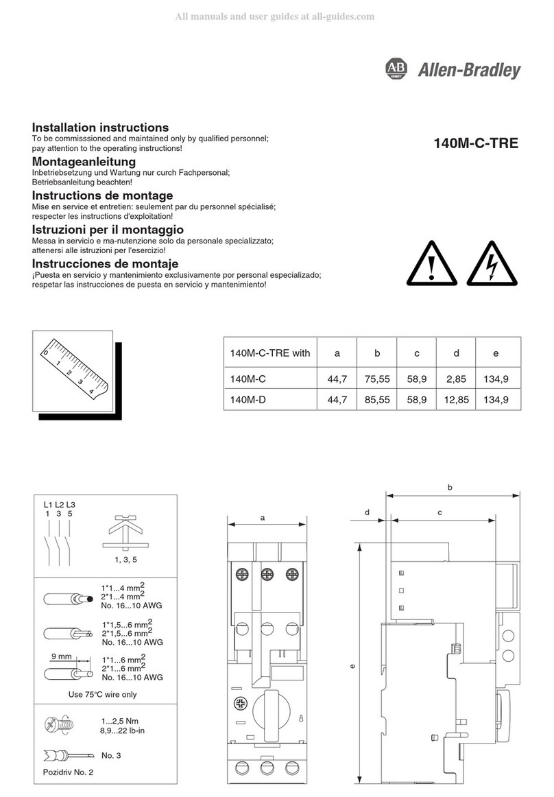
Rockwell Automation Allen-Bradley 140M-C-TRE User manual

Rockwell Automation

Rockwell Automation Allen-Bradley 140M-C-TRE User manual

Rockwell Automation Allen-Bradley 140U Manual

Rockwell Automation

Rockwell Automation Allen-Bradley 140U Manual

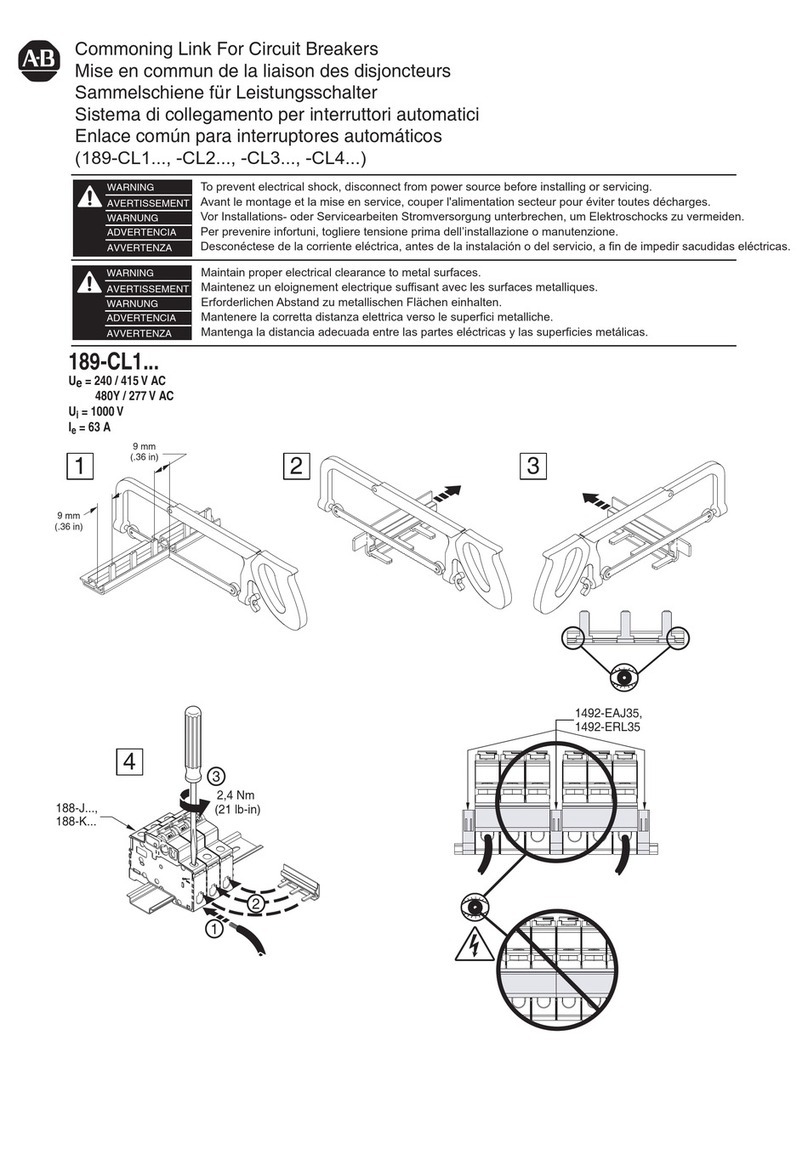
Rockwell Automation 189-CL1 Series User manual

Rockwell Automation

Rockwell Automation 189-CL1 Series User manual

Rockwell Automation Allen-Bradley 140G-N User manual

Rockwell Automation

Rockwell Automation Allen-Bradley 140G-N User manual

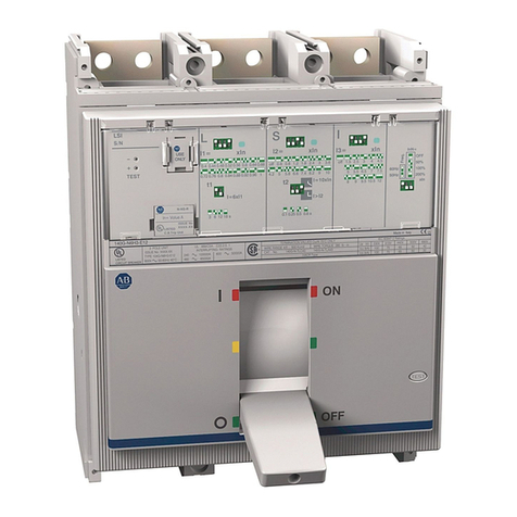
Rockwell Automation Allen-Bradley LSI User guide

Rockwell Automation

Rockwell Automation Allen-Bradley LSI User guide

Rockwell Automation Allen-Bradley 140U User manual

Rockwell Automation

Rockwell Automation Allen-Bradley 140U User manual

Rockwell Automation Allen-Bradley 140U User manual

Rockwell Automation

Rockwell Automation Allen-Bradley 140U User manual

Rockwell Automation 1492-GS1 Series User manual

Rockwell Automation

Rockwell Automation 1492-GS1 Series User manual

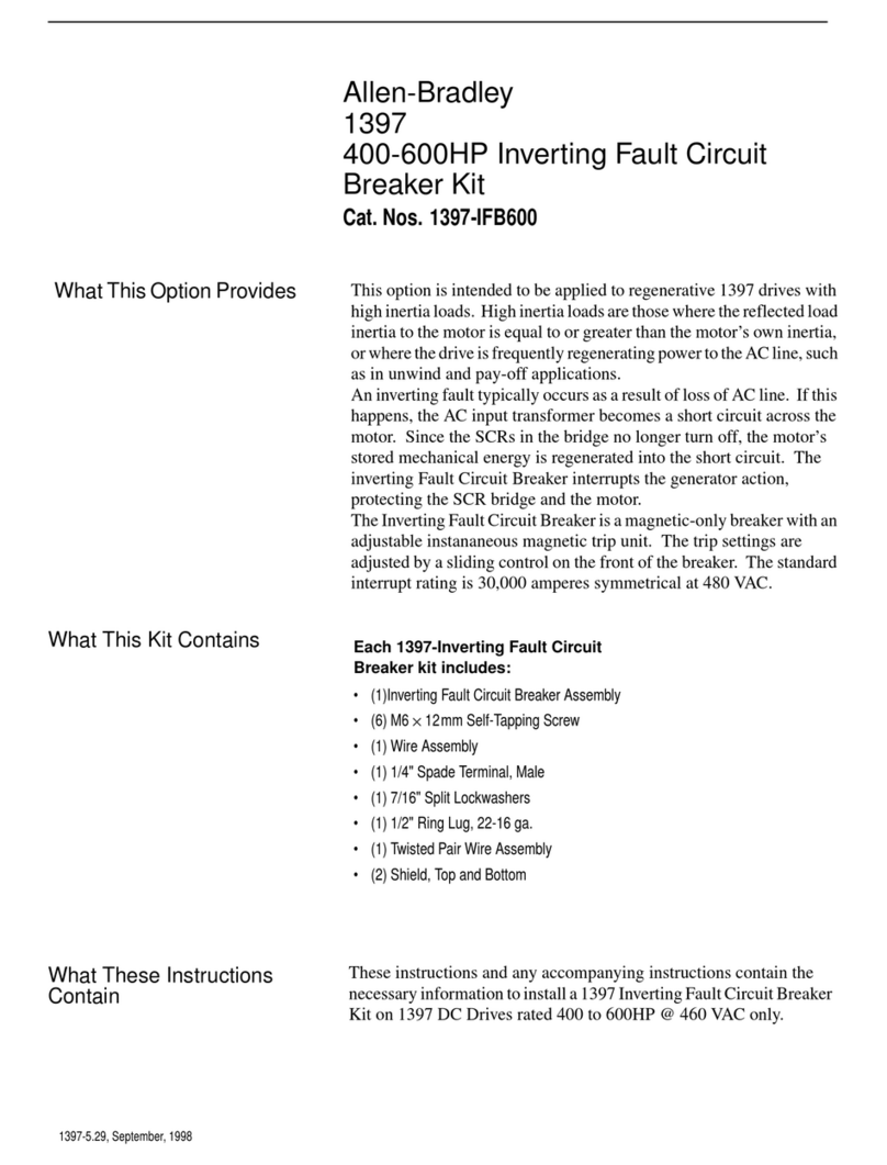
Rockwell Automation Allen-Bradley 1397 User manual

Rockwell Automation

Rockwell Automation Allen-Bradley 1397 User manual

Popular Circuit Breaker manuals by other brands

Eaton AGM2-10-PKZ0 Instruction leaflet

Eaton

Eaton AGM2-10-PKZ0 Instruction leaflet

Malmbergs MB-2169869 instruction manual

Malmbergs

Malmbergs MB-2169869 instruction manual

GE AKR-30 Series Maintenance manual

GE

GE AKR-30 Series Maintenance manual

Siemens 3AH6 operating instructions

Siemens

Siemens 3AH6 operating instructions

Siemens 3VM11 ED1 Series operating instructions

Siemens

Siemens 3VM11 ED1 Series operating instructions

Eaton 150VCP-W Series Interactive Instructions

Eaton

Eaton 150VCP-W Series Interactive Instructions

Siemens SENTRON 3WL10 manual

Siemens

Siemens SENTRON 3WL10 manual

Shihlin electric BW-2000 manual

Shihlin electric

Shihlin electric BW-2000 manual

hager hw+ user manual

hager

hager hw+ user manual

netvox RP02RH Series user manual

netvox

netvox RP02RH Series user manual

Westinghouse DE-ION DH Series Instruction book

Westinghouse

Westinghouse DE-ION DH Series Instruction book

Eaton RVU Series operating instructions

Eaton

Eaton RVU Series operating instructions

Eaton Series NRX Instruction leaflet

Eaton

Eaton Series NRX Instruction leaflet

Eaton QSA40N0 Series Instruction leaflet

Eaton

Eaton QSA40N0 Series Instruction leaflet

Siemens 3RV1.5 operating instructions

Siemens

Siemens 3RV1.5 operating instructions

nader NDM3EU Series product manual

nader

nader NDM3EU Series product manual

ABB SACE Emax 2 manual

ABB

ABB SACE Emax 2 manual

WEG DW-161 Assembly instructions

WEG

WEG DW-161 Assembly instructions

manuals.online logo
manuals.online logoBrands
  • About & Mission
  • Contact us
  • Privacy Policy
  • Terms and Conditions

Copyright 2025 Manuals.Online. All Rights Reserved.