G
F
Trip button(φ4)
Shaft
Pin of KAITENBAN
Joint
90
16
90
48
54
1.2
〜
3.2
125
±
2
61
A
D
E
C
E
D
B
C
B B
K
φ54
54
54
D
K
Protrusion for
KAITENBAN
(1)Do not use organic solvent to clean the Operating handle.
(2)The shaft of the adjustment unit comes out when the Front plate opens.
Be careful at the check in the enclosure.
(3)Be careful that the KAITENBAN and the shaft pin rotate when the Breaker is tripped
under opening the Front plate.
(4)Close the Front plate in the state that the Handle positionis united with the Breaker side.
(5)Operate the Handle with the power of 5N・m and under.
(6)The door lock mechanism doesn't have strength by which the entire door of the enclosure is maintained.
Please fix the door of the enclosure with the detent tool on the enclosure side.
(7)Don't operate the Handle unit under closing the Front panel, when the condition of the Operating unit was locked.
(8)It can not be operated when the mounting direction LINE and LOAD is mounted accidentally.
(9)Should not trip operation to OFF position.
(10)When the door is open, should not touch the live parts.
(11)Normal servise condition・maintenance and others have been described to Handling and Maintenance for Molded-case circuit breakers.
(12)Do not stop the turning ON・OFF and RESET operation on the way.
(13)The door is opened after confirming the handle is at the turning off position.(The horizontal)
Position
of Trip
button
1)Instruction Manual
(1pc)
Trip
button
Trip
button
●The marks used respectively mean the following.
CAUTION
CAUTION
1. Be sure to follow for the performance of IP65
2. Cautionary instructions for operation
3. Specification
IEC 60529 IP65
4. Installation for Operating handle
This means prohibition.
Never ignore this indication.
Be sure to follow these
instructions without fail.
Wrong handling can cause dangerous situation in whichi possibility of fatal
accidents or serious injuries assumed.
Warning for possible electrification
under certain conditions.
(1)Mounting the Operating unit
Mount the Breaker and the Operating unit in
the following matter.
M4
×
62
4)Handle unit mtg.
screws(with Washer)
3)Operating unit mtg.
nuts(2pcs)
:
M4
2)Operating unit mtg.
screws(2pcs)
:
(c)
Please confirm whether the delivered product is the same as the order's one.
Note1
2
3
Please contact us for other models except above table.
※
The Circuit Breaker's attached screws
Breaker mtg.screws
M4
×
55 (2, 3-pole
:
2pcs, 4-pole
:
3pcs)
:
(a)
M4
×
73 (2, 3-pole
:
1pc)
:
(b)
Outline
&
Dimensions
Plate
thickness
Front plate
Drilling Plan
breaker handle
KX
M4
×
0.7 screw
or φ5
0 or higher (5K+100)or higher
Center of
M4×0.7 screw
or φ5
Center of
breaker handle
2,3-pole 4-pole
Cutout Dimensions
Front Plate
Center of
Center of
breaker
Center of the
operating handle
Circuit
breaker
φ9
breaker handle and
Front plate
Center of
breaker
Center of
operating
handle
operating
handle
Left
Hinge
Right
Hinge
Upper figure shows the relative
position of breaker and hinges,
viewing from load side.
Operating unit mtg.nuts
M4(2pcs.)
Excluding two poles
Shaft unit
Breaker
Operating
unit
Pin of
KAITENBAN
F
G
Attached Parts
Dimensions (mm)
MCCB
Breaker type applicable
pole
ELCB
pole
There is no other application except above table.
2・3・4
30.5 861723039
37.5
100.5
35 20141
2・3・4
NF125-UV
V-1UV
V-1UVE
V-2UV
V-2UVE
NF250-UV
EABCD
Breaker type applicable
Adjustment unit
(
V-AD3S
)
Type
name
It cannot be used when the IEC 35mm rail mounting.
For correct operation,please go over
this paper "Instruction Manual for V
type Operating Handle" beforehand.
(
1
)
Operation Lock Mechanism
……
OFF-position lock.
(
2
)
Door Lock Mechanism
…………
The door can be opened with the OFF position only.
(
3
)
Mounting direction
………………
Vertically type(ON side of breaker is upper)
(
4
)
The degree of protection (IEC 60529)is IP65.
(
5
)
The products of which Cat. No. include "E" are for emergency stop equipments
and they have red Handle and yellow Front base.
(
6
)
Using the Adjustment unit as a option, it can be mounted to the different depth Panel.
(
7
)
When the trip button is pushed with the door opened, the breaker does trip.
The position of the trip button is different in the type name.
MOLDED-CASE CIRCUIT-BREAKERS
EARTH-LEAKAGE CIRCUIT-BREAKERS
INSTRUCTION MANUAL FOR V TYPE OPERATING HANDLE
5)Insulating cover
3-pole(1pc)
4-pole(1pc)
(a)and (b)of the securing screw is shown the location for Drilling Plan.
E
T
E
S
R
F
F
O
D
E
P
P
I
R
T
N
O
(a)(b)
Breaker
(a)
(a)
(a)
(a)
(a)
Breaker mtg. screw
1.2
±
20
%
N
・
m
M4
×
73
…
M4
×
55(4-pole)
Operating unit mtg. screw
1.2
±
20
%
N
・
m
M4
×
62
Breaker mtg. screw
1.2
±
20
%
N
・
m
M4
×
55
Insulating
cover Insulating
cover
②
Adjust the protrusion for KAITENBAN to
『
○
』
mark position,
mount the Operating unit on the Breaker by Operating unit
mtg. screws and Operating unit mtg.nuts.
③
Mount the Breaker with Operating unit on the board by
Breaker mtg. screws(2,3-pole
:
3pcs, 4-pole
:
4pcs).
①
Remove a Insulating cover before installing of the
Operating handle.
(Note
:
Be careful not to lose insulating cover mtg. screws.)
V-1UV, V-1UVE
a
b
c
b
c
a
V-2UV, V-2UVE
a
Insulating cover
mtg. screw (2pcs.)
Insulating cover
mtg. screw (4pcs.)
Note:Make a breaker OFF position.
13
2
4
X
Hinge
Front plate
Size of door
Pin for
KAITENBAN
Joint
C
B
A
X
175
□8
1.2
〜
3.2
F'(N)
F(N)
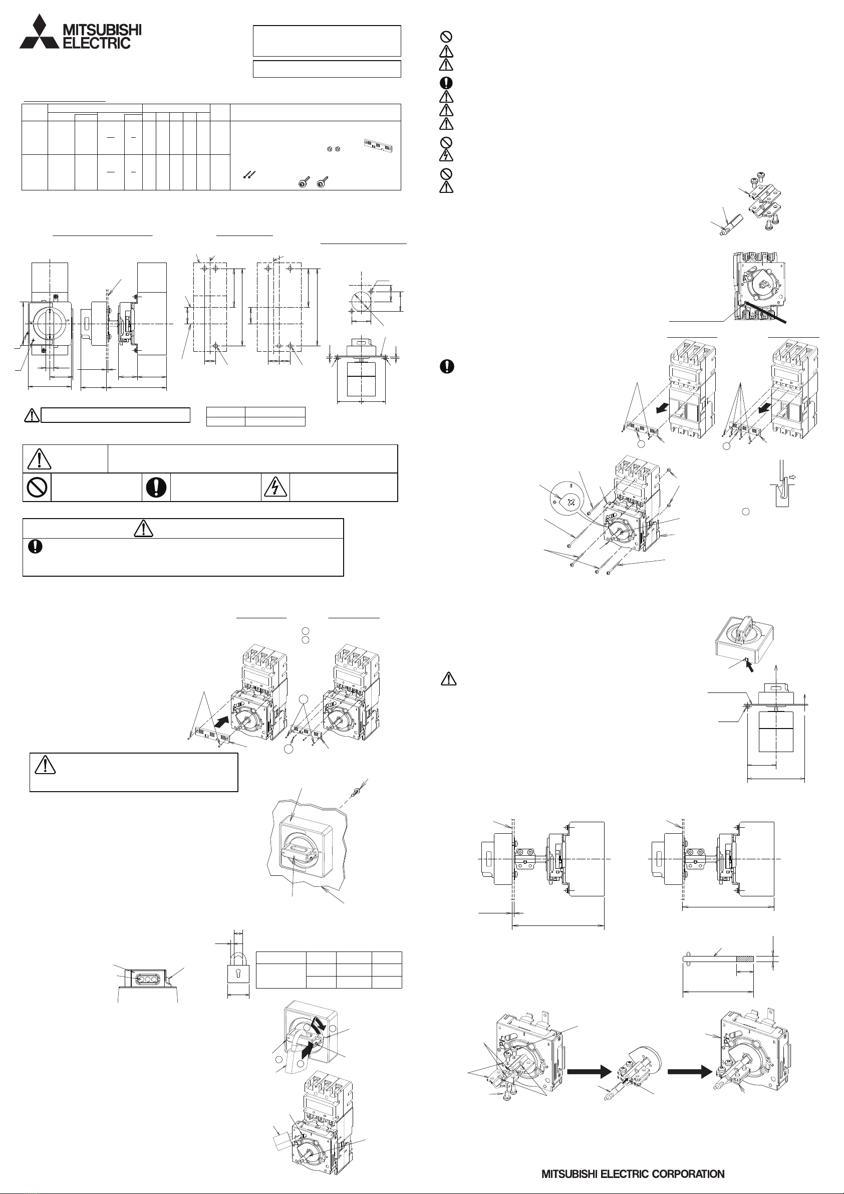
7. Adjustment unit (V-AD3S OPTION)
(
3
)
Installation
Joint mtg. screws
5.5, 6
22 or 23
40
51935
CBA(
)
Handle unit mtg. screws(with Washer)
M5
×
16(2pcs)
・・・
2.5
〜
3.5 N
・
m
(
1
)
Handle unit
(2)How to lock the Operating unit
2.5〜3.5N・m
M5×10(4pcs)
Front base
Front plate
Handle
●
Padlock (to be furnished by customer)
5. Lock Mechanism
6. Door Lock Mechanism
(2)Handle unit
●
How to lock the Handle unit
Note:The Lock plate operation-middle to operation load
may become heavy.
Please operate it until the hole of the center of
the Handle has opened.
(1)Please the door of the door when the space is generated by the distortion etc.of the door.
(2)Please tighten the screw of the handle unit surely by a regulated torque.
(3)Please front plate cutout according to front plate cutout dimensions.
Adjusting the height of the Front plate by installing the Adjustment unit in
the Operating unit becomes possible.
Please cut the Shaft of the Adjustment unit from installation plane of Breaker
according to the height of the Front plate.
Operating
unit
Turn the Handle toward the reset position
at the mark of case.(①)push the Lock plate(②).
return the Handle in OFF position(③).
Use the padlock through the Handle's hole to lock the Handle.
●
How to release the OFF lock
Please detach the Padlock, turn the Handle to reset
direction until the lock plate return to the former position.
(Please check that the Lock plate has plugged up
the hole of the center of the Handle.)
Circuit
breaker
The Operating unit can be locked in "OFF" position.
Insert a Padlock into the Lock hole in OFF position only,
and lock.
A 35,40mm Padlock or a Lockout Hasp can be used.
4.Fasten the Joint mtg.
screws securely.
(
1
)
The door can be locked in ON and TRIP position,
and opened in OFF position.
It is possible to open the door in ON and TRIP position
with pushing the Release parts.(Tool size:width 3×thick1.8mm)
(
2
)
Withstand load to the door interlock
Withstand load to the door F(N)is 200N on the center of
Operating handle.
Otherwise, The operating handle may be destructed.
Note
:Operating handle for 2Poles cannot be used.
When adjustment of Handle unit is not performed
as follows, the molded parts of
Handle unit and KAITENBAN may be broken.
P max
(
2
)
Shaft cutting
X =300 mm −P:V-1U*, V-2U*
(
1
)
Outline
&
Dimensions
Shaft
Cutting length
thickness
Plate
Enclosure
depth
Cutting
length
P
Front plate
Min.162
Front plate
Max.300
Mark of case
Padlock
Handle Lock plate
Lock plate
Padlock
Handle
Shaft unit
Padlock
Lock hole
Release parts
1.Adjust the Pin
for KAITENBAN
to square hole
of Joint.
2.Fasten the Joint temporally
by Joint mtg. screws(4pcs)
Shaft
3.Insert the Shaft until
the end of KAITENBAN
to the space for Joints.
Please insert the pin of
a KAITENBAN, and the pin of
a shaft according to the
same direction.
Insulating cover Insulating cover
④
Mount the Insulating cover contained in the package
of the Operating handle.
Note
:
(Insulating cover mtg.screw should use what
was assembled to the breaker.)
Insulating cover
mtg. screw(2pcs.)
0.6〜1.0N・m
Insulating cover mtg. screw(4pcs.)
…3.5×10:1.2±20%N・m
…3×10 :0.6〜1.0N・m
Breaker mtg. screw
1.2
±
20
%
N
・
m
M4
×
55
U-form projection
Push the tip of the U-form
projection fully toward
the arrowed direction by
the screw driver etc.and
pull out the insulating
cover sliding the upper
direction
Mount the handle unit on the front plate by attaching screws from back
side temporarily. The handle unit should be disposed in positions on the
center of the front panel.
Adjust the handle unit in every direction after mounting, if it does not
work properly with the action below
;
①
ON and OFF operation should be carried out smoothly.
②
When turning the handle from OFF state to the right in a few degrees,
it should be returned automatically. Also it should be kept indicating
OFF state even if applying light loads in the reset direction.
③
When opening the front plate by release operating, it should be closed
smoothly.
④
The operating handle should be parallel to the breaker.
After adjusting, tighten the screws completely.
Dimension of Padlock (mm)
Dimension C
:
8mm or less can be applied.
All
types
Application
Normal
size
Use any Padlock available in market.
The Operating handle can be locked at OFF position.
It can be used the up to 3 Padlocks(A=35,40mm)or
the Lockout Hasp. When the operating handle is locked
in the OFF position by using the Padlock, the door
cannot be opened.
-1- -2-
-3- -4-
XX
V-1UV, V-1UVE V-2UV, V-2UVE
(2pcs)
:
M5
×
16


