Mitsubishi Electric AE-SW Series User manual

22A
ENGLISH
CHINESE
中文
AE630-SW AE1000-SW AE1250-SW AE1600-SW
AE2000-SWA
AE2000-SW AE2500-SW AE3200-SW
AE4000-SWA
AE4000-SW AE5000-SW AE6300-SW
本手册适用于以下型号产品
使用说明书
対象機種
三菱低压空气断路器 World Super AE
MITSUBISHI Low-Voltage Air Circuit Breakers series
World Super AE
AE-SW
ご使用の前に必ずこの取扱説明書をお読みください。
この説明書は、最終ユーザまでお届けください。
IMPORTANT NOTE: Before using these Series AE breakers, please read these
instructions carefully, and make sure that all actual users also read them.
JAPANESE
三菱低圧気中遮断器 World Super AE
取扱説明書
Types covered in this manual
重要注释: 在使用 AE 断路器系列以前,请务必仔细阅读本说明书,
并确保所有用户也阅读本说明。
MODEL
INSTRUCTION MANUAL

E-2
Safety precautions
This means prohibition. Never ignore
this instruction.
Warning for possible outbreak of a fire
under certain conditions.
Warning for possible electrical shock
under certain conditions.
Do not use the product under the conditions with over-rated current. Otherwise, ground-fault or short circuit fault
could occur due to dielectric breakdown, or explosion could occur due to a short circuit protection failure.
Do not touch terminal area. There is a risk of electrical shock.
Be sure to follow these instructions
without fail.
Before using this device, make sure to read this instruction manual thoroughly.
Important safety information is included in this manual. Be sure to follow the instructions.
Please make sure that the end user receives this instruction manual.
This instruction manual is prepared for an electrical expert.
Symbols have the following meaning.
Incorrect handling of the
product will result in a haz-
ardous situation, such as
death or serious injury.
Incorrect handling of the
product may result in a
hazardous situation ac-
cording to circumstances.
The electrical work shall be performed by qualified personnel (electrical expert).
Inspection and maintenance should be performed by qualified personnel (electrical expert). Before performing wir-
ing works, turn off the upstream circuit breaker. Failure to do so may expose you to electrical shock.
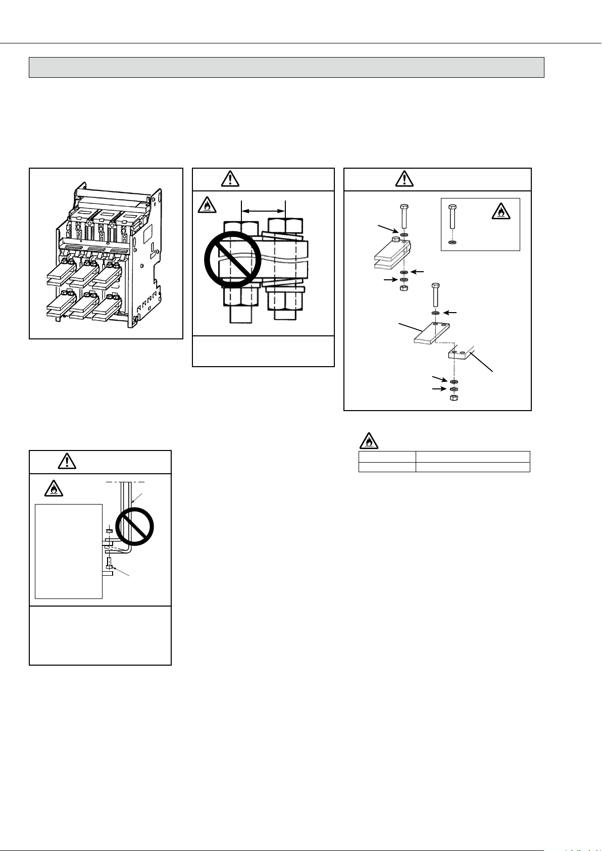
Tighten the terminal screw with the torque specified in the instruction manual. Failure to do so may cause a fire.
Do not install or store in an abnormal environment with high temperature, high humidity, dust, corrosive gas, vibra-
tions, or shocks, etc. To do so may cause a fire, malfunction of the circuit breaker or make it inoperative.
Protect the circuit breaker so that foreign particles, such as dust, concrete powder and iron powder, and rain water
will not enter the circuit breaker. Failure to do so may cause malfunction or fire.
When the circuit breaker trips automatically, remove the cause before turning on the handle. Failure to do so may
cause an electric shock or a fire.
Retighten the terminals periodically. Failure to do so may cause a fire.
Use the product in 50/60 Hz. Failure to do so may cause malfunction, inoperativeness or fire.
Do not use in strong magnetic field.
When using a transceiver, keep it off at least 1 meter from the ACB.
Do not disassemble.
Malfunction and operation fallures can be caused.
Dispose of the product as industrial waste.

E-3
ENGLISH
Table of contents
Safety precautions ………………………………… 2
External view………………………………………… 4
Internal structure …………………………………… 5
Outline dimensions and product weight ………… 5
Unpacking …………………………………………… 6
Storage ……………………………………………… 6
Transportation ……………………………………… 7
Installation …………………………………………… 8
Installation of the drawout handle………………… 9
Installation of the inter-phase barrier (BA) ……… 9
Connection ……………………………………… 10
Insert operation ………………………………… 12
Drawout operation ……………………………… 14
Charging operation ……………………………… 16
Open/close operation …………………………… 17
Door interlock (DI) ……………………………… 19
Cylinder lock (CYL) and Castell lock (CAL) …… 19
OCR alarm (AL) [MRE: manual reset type] …… 19
Shutter lock (SST-LOCK) ……………………… 20
Safety shutter nameplate ……………………… 20
Functions of electronic trip relay (ETR) parts … 21
Characteristics setting for the WS type ……… 23
Characteristics setting for the WM type ……… 24
Characteristics setting for the WB type ……… 25
Characteristics setting for the WF type ……… 26
Characteristics setting for the optional setting modules
… 28
Setting procedure for the electronic trip characteristics
… 30
Wiring diagram …………………………………… 32
Technical notes (Arc space, Reverse connection)
… 34
Technical notes (Performance of withstand voltage)
… 34
Technical notes (Operation environment)……… 35
Warranty ………………………………………… 35
Inspection and maintenance …………………… 36
Service network ………………………………… 42

E-4
External view
< Fixed type >
Note: The fixed type includes lifting hook (HP).
< Drawout type >
Fig. 4-1 Fig. 4-2
Drawout state
Cradle
Drawout position indicator
Aperture for the drawout handle
Lock plate
Drawout handle
Extension
rail
Lifting holes
Control circuit terminal
block
Fixing bolts (P.13)
Back mounting hole (P.8)
Fig. 4-3
Note: The drawout type includes a drawout handle.
Fig. 4-1 shows AE1600-SW 3-pole fixed type, Fig. 4-2 shows AE1600-SW 3-pole drawout type, and Fig. 4-3 shows AE6300-
SW 3-pole drawout type.
<Drawout type>
Arc-extinguishing
chamber
OFF button
ON button
Charging handle
Charging indicator
ON/OFF indicator
Rated nameplate
Manual reset button (option)
Electronic trip relay
(ETR)
Padlock hook
Control circuit terminal block
Lifting hook (HP)
allows a padlock to
be attached to the
OFF button

E-5
ENGLISH
b
a c d7
17 c d
a(Max.)
b
Aperture for the drawout handle
Operating panel center
200
Drawout handle
Max. 173
200
Internal structure
①Control circuit terminal block
②Control circuit connector
③Auxiliary switch
④
Shunt trip device, closing coil, undervoltage trip device
⑤Electronic trip relay (ETR)
⑥Cover
⑦Open/close mechanism
⑧Drawout mechanism
⑨Intermediate base
⑩Arc-extinguishing chamber
⑪Contact on the movable side
⑫Contact on the fixed side
⑬Conductor on the breaker
⑭Conductor on the cradle
⑮Main circuit junction
⑯Base
⑰Contact spring
⑱Flexible conductor
⑲Conductor on the breaker
⑳Conductor on the cradle
Power supply CT
Current sensor coil
Cradle
Cradle nameplate
Table 5-1
Outline dimensions and product weight
Model
AE630-SW
AE1000-SW AE1250-SW AE1600-SW
AE2000-SWA
340 × 410 × 290 × 108
425 × 410 × 290 × 108
300 × 430 × 375 × 104
385 × 430 × 375 × 104
44
54
62
75
27
32
340 × 410 × 290 × 40
425 × 410 × 290 × 40
300 × 430 × 375 × 61
385 × 430 × 375 × 61
35
42
56
70
42 43
35
43
56
70
35
56
70
24
28
Outlinedimen-
sions
Note 1)
a × b × c × d
(mm)
3 poles
4 poles
3 poles
4 poles
3 poles
4 poles
3 poles
4 poles
3 poles
4 poles
Product
weight
(kg)
Note 2)
Fixed
type
Drawout
type
Fixed
type
Drawout
type
Cradle
only
Fig. 5-1
Fixed type
Fig. 5-2
Note 1)
d dimensions: when the product is connected horizontally. For AE2000-SWA, when it is connected vertically.
Note 2)
Weight (reference value) when an electronic trip relay is attached. It does not include any other accessories.
(Breaker OFF and charging)
Table 5-3
AE4000-SW AE5000-SW AE6300-SW
141
159(179)
194
223(247)
98
113(127)
148
166(188)
208
238(269)
107
121(138)
874 × 414 × 290 × 136
1004(1134) × 414 × 290 × 136
889 × 480 × 375 × 123
1019(1149) × 480 × 375 × 123
Model
Outlinedimen-
sions
Note 1)
a × b × c × d
(mm)
3 poles
4 poles
3 poles
4 poles
3 poles
4 poles
3 poles
4 poles
3 poles
4 poles
Product
weight
(kg)
Note 2)
Fixed
type
Drawout
type
Fixed
type
Drawout
type
Cradle
only
Note 1) d dimensions: it is connected vertically.
Note 2)
Weight (reference value) when an electronic trip relay is attached. It does not include any other accessories.
Table 5-2
AE2000-SW AE2500-SW AE3200-SW
51
64
81
101
33
40
52
64
81
101
54
67
85
106
34
42
AE4000-SWA
475 × 410 × 290 × 117
605 × 410 × 290 × 117
439 × 430 × 375 × 109
569 × 430 × 375 × 109
73
92
101
127
46
58
475 × 410 × 290 × 40
605 × 410 × 290 × 40
435 × 430 × 375 × 61
565 × 430 × 375 × 61
Model
Outlinedimen-
sions
Note 1)
a × b × c × d
(mm)
3 poles
4 poles
3 poles
4 poles
3 poles
4 poles
3 poles
4 poles
3 poles
4 poles
Product
weight
(kg)
Note 2)
Fixed
type
Drawout
type
Fixed
type
Drawout
type
Cradle
only
Note 1)
d dimensions: when the product is connected horizontally. For AE4000-SWA, when it is connected vertically.
Note 2)
Weight (reference value) when an electronic trip relay is attached. It does not include any other accessories.
①
②
③
④
⑤
⑥
⑦
⑧
㉔
⑨
⑩
⑪
⑫
⑬
⑭
⑮
⑯
⑰
⑱
⑲
⑳
㉑
㉒
㉓
Fig. 5-3
Fig. 5-4
Drawout type

E-6
Accessories
nameplate
CT rated
nameplate
Rated
nameplate
+60°C
-20°C
Store within
this range.
Storage
Unpacking
①Make sure that the packing case is free from any abnormality such
as being broken and/or wet.
②Check the indication on the package and the rated nameplate of the
breaker, and confirm that it matches your order.
Serial number is indicated on the rated nameplate and on the cradle
nameplate (Fig. 5-1).
Fig. 6-4
* If this product is used after being stored for more than 6 years, maitenance is required including lubrication etc. before
operation. Please contact our representative office.
Fig. 6-5 Fig. 6-6 Fig. 6-7
Fig. 6-9
Fig. 6-10
OFF
H2S 0.01 ppm or less
SO20.05 ppm or less
NH30.25 ppm or less
Relative humidity 85% or less,
without condensation
Avoid humidity Avoid direct sunlight
Avoid direct sunlight during usage. Failure to do so could
result in temperature rise and malfunction. It could also
lead to discoloration of nameplates and molded cases.
Average daily temperature
+35 °C or less
Storage temperature
-20 °C to +60 °C
Caution on dust Avoid corrosive gases
Store in the OFF and DISCHARGED state.
Fig. 6-1 Fig. 6-2 Fig. 6-3
*This is not
included.
Baseplate for fixing Installation
screw
Fixed type
Installation
bracket
Drawout type
Completely seal the product
with the packaging case or a
plastic bag.
Store the drawout type in the CONNECT position.
Fig. 6-8
No direct storage

ENGLISH
E-7
Transportation
Fig. 7-1 Fig. 7-2
Do not roll the product.
Fig. 7-3
Fixed type
Fig. 7-4
When transporting the product with its
cradle attached, check that the lock plate
is protruded in the CONNECT position. Do
not use anything else but the lifting holes.
Drawout type
Fig. 7-5
Since the conductors side is heavy,
be careful not to give an impact to
the product and the conductors when
landing the product.
CONNECT position
Locking plate
Lifting hook hole
25
R12.5
10
Wire length 1 m or more Wire length 1 m or more
1 m or longer
Fig. 7-6
When transporting a drawout type
breaker (AE4000-SW ~ AE6300-SW), be
sure to use 4 wires with a length of 1 m
or longer, or a lifter.
Take caution not to scratch
the control circuit termi-
nal block when lifting the
product with the lifting
hook (HP). Securely attach
the lifting hook (HP) so
that they will not come off
during transportation.
Do not drop the product during
transportation and storage.
Lifting hook (HP)

E-8
M8
Earth terminal
M12
Max.
14 mm
Bolt
Nut
Installation
Installation surface flatness
1 mm or less
1 mm or less
Fig. 8-1
< Drawout type >
Fig. 8-2
AE630-SW ~ AE3200-SW, AE2000-SWA, AE4000-SWA
Insert M12 bolts from above, and attach the cradle.
For AE4000-SW ~ AE6300-SW 3-pole and 4-pole (HN) products, insert four M12 bolts from the bottom and two from
the back and attach the cradle as shown in Fig. 8-3. For the 4-pole (FN)* products, insert six M12 bolts from the bot-
tom and two from the back and attach the cradle as shown in Fig. 8-4.
Perform drawout operation (connect position to drawout position) as instructed. (Refer to P.14 and 15)
M8 Earth terminal
(standard supply)
Fig. 8-8
< Fixed type >
Lifting using a lifter or with
lifting hook(HP)
Fig. 8-5
Fig. 8-6
Fig. 8-7
Lift
Supporter
On AE4000-SWA,AE4000-SW ~ AE6300-
SW, the center of gravity of the cradle
is located at the terminal position.
When the main body is removed from
the cradle, the cradle may turn over
backward. Take measures against
overturning.
When the main body is drawn out,
the center of gravity shifts to the
front. If the cradle is not secured,
take measures against overturning
and dropping.
Fig. 8-3 Fig. 8-4
AE4000-SW ~ AE6300-SW 3-pole & 4-pole (HN) AE4000-SW ~ AE6300-SW 4-pole (FN)*
Installation bracket (Panel side:non-magnetic steel)
Installation bracket
(Panel side:non-magnetic steel)
Cradle
2×M12 2×M12
6×M12
4×M12
M12
lMounting direction
l
Earth terminal
Unless there are any special circumstances, connect the earth terminal to the ground.
Precautions for mounting
Max.
25 mm
Max.
25 mm
Weld nut
(included
as standard)
Bolt
Weld nut
(included
as standard)
Bolt
Fig. 8-9
*4-pole product (FN): 4-pole product of which neutral poles have the same current capacity
as the other poles.
* Insertion direction of bolts is arbitrary.
CAUTION
CAUTION
lAppropriate tightening torque
Bolt size
M12 45±5
Tightening torque (N∙m)
lAppropriate tightening torque
Bolt size
M12 45±5
Tightening torque (N∙m)

ENGLISH
E-9
Fig. 9-1
Installation of the drawout handle
The drawout handle can be installed either onto the right or left of the cradle as required.
A drawout handle, installation bracket, installation screws, and hexagon nuts are provided with the breaker.
Fig. 9-2
Fig. 9-3
Note) When a mechanical interlock (MI) or
door interlock (DI) is attached, the dra-
wout handle cannot be installed onto
the right side of the cradle.
Installation bracket
Cradle
Drawout handle
Installation screw (+) M5 × 12 (supplied)
Tightenning torque:3.2 ± 0.4 N∙m
Hexagon nut M5 (supplied)
Mechanical interlock (MI)
or Door interlock (DI)
Installation onto the left side Installation onto the right side
Installation of the inter-phase barrier (BA)
Insert in the slot on the breaker. (Refer to Fig. 9-4 and Fig. 9-5)
Fig. 9-4
< Fixed type > < Drawout type >
Fig. 9-5

E-10
Connection
Use M12 screws (made of copper), spring washers, and small washers to connect to the conductors.
Clean the contact surface and securely tighten the screws with a appropriate torque.
The connecting area on main circuit terminal of the breaker is different depending on the shape of the breaker’s terminal.
Refer to the outline dimensions in the catalog.
25mm
Main circuit
Fig. 10-1 Use small washers to connect that
the washers do not overlap with each
other.
Fig. 10-3
Fig. 10-2
Please tighten screws after checking
breaker’s terminal and conductor
certainly contact with each other.
Make sure the conductor doesn’t
apply the force to breaker’s terminal
in any direction.
Fig. 10-4
Bolt
Breaker
Conductor
Bolt size
M12 45±5
Tightening torque (N·m)
Keep an insulation distance between the
conductors to be connected according to the
standard of the panel.
Appropriate tightening torque for
conductor connection
Horizontal connection
Small washer
Small washer
Spring
washer
Spring washer
Small washer
Small washer
Conductor
Breaker terminal
(silver plated)
M12
45±5N·m
CAUTION
CAUTION
CAUTION

ENGLISH
E-11
Control circuit terminal block
Tighteing with excessive torque above the specification may cause damages of
terminals and screws.
Be sure to tighten with the specified torque.
After removing screws, make sure not to tighten the screws diagonally.
Be careful not to apply excessive tension to the wirings.
Use a cross-head screwdriver with a diameter that matches the cross-shaped
groove.
M3.5................................. No. 2
Since fault current owing through the conductors causes large electromagnetic forces, the conductors should be
secured rmly, using the values in the below table as a reference. Max. distance between xing support and breaker
bus bar should be less than 200mm.
When selecting conductors to be connected to the breakers, ensure that they have a sufcient current capacity. Refer to the right table.
Breaker
Conductor
Supporting xture
Supporting between live parts of
different poles and between the
power supply and load terminals.
200 mm or less
Fig. 11-1
Table 11-1
Electromagnetic force per 1 m of conductor (in the case of three phase short circuit)
30(0.2)
42(0.2)
50(0.2)
65(0.2)
75(0.2)
85(0.2)
100(0.2)
130(0.2)
5700
11200
15800
26700
-
-
-
-
7700
15100
21400
36100
-
-
-
-
5100
9900
14000
23600
31500
40400
-
-
3500
6800
9600
16200
21500
27600
-
-
3900
7600
10700
18100
24100
30900
-
-
4300
8500
12000
20200
26900
34500
-
-
4500
8900
12600
21200
28200
36200
-
-
Prospective fault current kA (pf)
Conductor distance (mm)
Type
AE630-SW ~
AE1600-SW
AE2000-SWA
AE2000-SW ~
AE3200-SW
AE4000-SW ~
AE6300-SW
3 poles 4 poles 3 poles 4 poles
85 115
6300
12200
17300
29300
-
-
-
-
105 130 190 170 152 145
2500
5000
7000
11800
15800
20000
27800
47000
262
AE4000-SWA
Drawout type Fixed type
3 poles 4 poles
(N/m)
2
2
2
2
3
4
3
2
4
4
4
4
3
Vertical
Conductor to be connected (copper)
Rated current
MAX (A) ArrangementQuantity Conductor size (mm)
Table 11-2
Conductor size
(IEC 60947-1, Ambient Temp. 40 °C, Open air)
*1 For 3200 A, connect a conductor which is sized for 3150 A.
For 3200 A or higher, there is no specication by IEC (IEC 60947-1). (Specication by the manufacturer)
40 x 5
60 x 5
80 x 5
100 x 5
100 x 5
100 x 5
100 x 10
150 x 10
150 x 10
150 x 10
100 x 10
150 x 10
200 x 10
630
1000
1250
1600
2000
2500
3200*1
AE4000-SWA
drawout type
AE4000-SWA
xed type
4000
4000
4000
(AE4000-SW)
5000
6300 Fig. 11-2
2m
Breaker
3m
(Note) Table 11-2 shows the conductor size that is indicated in IEC 60947-1
with an ambient temperature of 40 °C and in an open air environment.
Fig. 11-2 shows the testing conditions.
M3.5 x 10
Torque: 1.0 ± 0.2N·m
Fig. 11-3 Fig. 11-4 Fig. 11-5
A = 7.2 mm or less
Control circuit terminal block
Applicable crimp-type terminals
A A
Applicable crimp-type terminals
for M3.5 screws with an outer
diameter of 7.2 mm or less.
(Wire size 1.25 mm2~ 2.0 mm2)
Crossover wiring

E-12
Insert operation
DRAWOUT positionCONNECT position
①
Pull the lock lever toward you (step 1), unhook the lock lever
from the cradle, and then pull out the extension rail (step 2).
②
With the extension rail pulled out to the furthest position, lift the
breaker once by using a lifter or dedicated lifting hook (HP), and
then lower the breaker down onto the drawout rail. Place the
dent of the breaker onto the notch of the drawout rail. (Fig. 12-5)
④Insert the drawout handle while pressing the OFF
button. Check that the drawout position indicator indi-
cates DISCONNECT (Fig. 12-7).
Using a lifter or with lifting hook (HP)
Fig. 12-2
②
Drop
Pinched finger
When placing the breaker in
the panel, take care not to hurt
your fingers or hands with the
in-panel structure.
(Prohibition)
Do not insert the drawout handle without pressing the
OFF button. When inserting or pulling out the drawout
handle or during operation, be sure to place the dra-
wout handle straight into the Aperture for the drawout
handle. Failure to do so could result in breakage.
Fig. 12-1
①
Extension rail
Lock lever
Step 1
Step 2
Breaker dent
Rail notch
Fig. 12-5
Fig. 12-4
DISCONNECT position
Fig. 12-7
If the breaker is placed on the rail
while the cradle is not secured, the
center of gravity shifts forward. Be
sure to take preventative measures
against the unit tipping over.
④OFF button
Press
Insert
Drawout handle
Aperture for the
drawout handle
Fig. 12-6
③
With the extension rail pulled out to the furthest position, slowly push
the breaker in until you hear the clicking sound when it does not move.
When inserting the breaker from the DRAWOUT position to the
DISCONNECT position, be sure to do so evenly on the right and
left sides. (Do not forcefully push the right or left terminal area only.)
If it is uneven (if the breaker is inserted diagonally), it does not go in
smoothly.
For a breaker installed in an elevated location, perform this opera-
tion with two people.
Click!
Fig. 12-3
③
CAUTION
CAUTION

ENGLISH
E-13
Latch
Unlock position
Cover
Push
Lock plate
Lock position
⑤Press in the lock plate until it clicks onto the latch, and
unlock.
(Caution)
(a) If unlocking the lock plate feels difficult, slightly rotate
the drawout handles to the right or left.
(b)
Be sure to push in the lock plate to the unlock position.
The position indicator may not operate correctly.
Fig. 13-1
⑤
⑥Unlock, release your hands from the lock plate, and
rotate the drawout handle clockwise.
(Caution)
Do not draw out during the insert operation. The
drawout position may not be indicated correctly. If that
is the case, pull out the breaker to the DISCONNECT
position once, and then retry the insert operation.
Fig. 13-2
⑥
⑨
Fig. 13-5
Fixing bolt
⑨For AE4000-SW ~ AE6300-SW, always tighten the fix-
ing bolts on both sides of the cradle as shown in Table
13-5, and securely fix the breaker.
⑦When the breaker is inserted to the testing position,
the drawout position indicator shows TEST position,
and the lock plate is protruded automatically, locking
the drawout handle rotation.
(Caution)
Do not rotate the drawout handle while the lock plate is
protruded.
TEST position
Fig. 13-3
⑦
⑧
Insert the lock plate, and rotate the drawout handle
clockwise. When the breaker is inserted to the CONNECT
position, the lock plate is protruded automatically,
completing the insert operation. At this time, the drawout
position indicator shows the CONNECT position. For all
breaker types, the operation load becomes heavy during
operation from the TEST position to the CONNECT position
or at the main circuit junction insertion position, but this is
not a fault.
Fig. 13-4
(Caution)
(a) After completing the insertion, do not rotate the
drawout handle.
(b) The drawout position indicator shows the position
(CONNECT, TEST) when the lock plate is protruded.
When the lock plate is unlocked, it shows a
reference position.
(c) The breaker cannot be closed with the drawout
handle inserted.
⑧
Checkpoint 1
Lock plate is protruded
Automatic
Checkpoint 2
In CONNECT position
Be sure to insert until the lock plate is protruded. If it
is not protruded, the connection may be incomplete.
CAUTION

E-14
Unlocked state
Lock plate
Latch
Cover
Push
Unlock position
Lock position
OFF button
Push
Drawout handle
Drawout operation
CONNECT position DRAWOUT position
②Insert the drawout handle while pushing the OFF button.
Fig. 14-3
②
(Prohibition)
Do not insert the drawout handle without pressing
the OFF button. Failure to do so could result in
breakage.
Fig. 14-4
③
Fig. 14-5
④
CONNECT position
Fig. 14-2
Fig. 14-1
①
④Unlock, release your hands from the lock plate, and
rotate the drawout handle counterclockwise.
(Caution)
Do not insert during the drawout operation. The
drawout position may not be indicated correctly.
To perform the insert operation, pull out the breaker
to the DISCONNECT position once, and then retry
the insert operation. When transitioning from the
CONNECT position to the TEST position, and when
the breaker terminals are detached from the main
circuit junction, the operation may feel light, but this
is not a fault.
①For AE4000-SW ~ AE6300-SW, unfasten the two fixing
bolts on both sides of the cradle, and unlock. If dra-
wout is performed without unlocking, the cradle and
the drawout mechanism may be damaged.
(Fig. 14-1)
③Push in the lock plate until it clicks onto the latch, and
unlock.
(Caution)
(a) If unlocking the lock plate feels difficult, slightly
rotate the drawout handles to the right or left.
(b) Be sure to press in the lock plate to the unlock
position. The position indicator may not operate
correctly.

ENGLISH
E-15
Lock lever
TEST position
Automatic
⑤When the breaker is drawn out to the TEST position,
the drawout position indicator shows TEST position,
and the lock plate is protruded automatically, locking
the drawout handle rotation.
(Caution)
Do not rotate the drawout handle while the lock
plate is protruded.
Fig. 15-1
⑤
⑥Next, insert the locking plate and rotate the handle
counterclockwise until the drawout position indicator
shows DISCONNECT and the breaker does not move.
Drawout operation is now completed.
The breaker can be pulled out using both hands.
(Caution)
(a) The lock plate sometimes gets protruded before
reaching the DISCONNECT position. If that is the
case, push in the lock plate to stay in the unlocked
state, and continue rotating the handle.
(b) If unlocking the lock plate feels difficult, slightly
rotate the drawout handles to the right and left.
(c) At the DISCONNECT position the drawout handle
may spin around without the lock plate being
protruded.
⑦To detach the breaker from the cradle, pull the lock lever
toward you, unhook, pull out the extension rail evenly on
the right and left side, and then pull out the breaker.
Fig. 15-2
⑥
Fig. 15-4
⑦
When pulling out the breaker,
take care not to hurt your fin-
gers or hands with the in-panel
structure.
Pinched finger
Drop
DISCONNECT
position
Fig. 15-3
By pulling the breaker, the
center of gravity shifts forward.
Be sure to take preventative
measures against a fall or drop
when the cradle is not secured.
CAUTION
CAUTION

E-16
Charging operation
Fig. 16-3
Manual charging operation is also possible using the
charging handle.
Although the charging motor has a short time rating it can
be continuously operated for up to ten times.
Since the charging complete switch is separate from the
motor charging circuit, the sequence can be arranged as
required.
Fig. 16-2
Table 16-1 Motor charging rating
< Motor charging (MD) >
Option
The closing spring is charged by an electric motor. When
the breaker is closed, the spring is charged automatically
(ON-charge method).
Rated
voltage
(V)
Applicable
voltage
range
(V)
Applied
voltage
(V)
Current
[Peak value]
(A)
time
(s)
Inrush
Steady
current
(A)
Charging
time
(s)
24DC
48DC
100-125
AC/DC
200-250
AC/DC
18 ~ 26.4
36 ~ 52.8
85 ~ 137.5
170 ~ 275
24
48
100
125
200
250
22
14
10(10)
12(12)
5(7)
6(8)
6
3
3(4)
3(4)
1(2)
1(2)
≤
5
< 0.4
< 0.4
AC: < 0.45
DC: < 0.25
AC: < 0.45
DC: < 0.25
Criterion for
power
requirement
(VA, W)
500
700
1000
700
1000
Note1 ) Values in parentheses show values for AE4000-SWA 4 pole and AE4000-SW ~ AE6300-SW.
Note2 ) We cannot manufacture AE4000-SWA 4 pole and AE4000-SW ~ AE6300-SW in 24V DC and
48V DC rating.
Note3 ) When choosing from the power supply capacity required to perform motor charging, make sure
that its voltage after a voltage drop at power input is still within the applicable voltage range.
Note4 ) These values are for reference, not guaranteed values.
Note5 ) Common use for 50 and 60Hz in AC.
< Manual charging >
Press the charging handle down at full stroke 7 or 8 times
until a click sounds. (It is completion when a charging han-
dle becomes light.) Then, the closing spring will be fully
charged. The charging indicator will show CHARGED.
Charging handle
Motor charging circuit diagram
Charged Signal
M
Breaker
Control
relay Motor charging
circuit
Charging limit
switch
Charging completion switch
Motor
Control supply
413
414
U1
U2
For 24VDC and 48VDC, the Diode rectier is
not included.
⑧When pulling out the breaker, be sure to do so evenly
on the right and left sides.
(Do not forcefully pull the right or left area only.)
If it is uneven (if the breaker is coming out diagonally),
it does not come out smoothly.
For a breaker installed in an elevated location, perform
this operation with two people.
(Caution)
AE4000-SWA and AE4000-SW ~ AE6300-SW have
their cradle center of gravity on their terminal areas.
Be sure to take preventative measures against a fall or
drop by installing a support for the cradle (Fig. 16-1).
Fig. 16-1
⑧
Model
AE630-SW ~ AE1600-SW,
AE2000-SWA 3pole
AE2000-SW ~ AE3200-SW,
AE2000-SWA 4pole, AE4000-SWA
AE4000-SW ~ AE6300-SW
30N·m
40N·m
* Values in the tables are reference values.
Charging operation power
OFF charging method is also available.
The closing spring is charged
automatically when the breaker is
opened. This is available only by
externally connecting b contact (AXb) of
the auxiliary switch to the motor
charging circuit in series.
In case of DC power supply, please use
high capacity auxiliary switch (HAX).
OFF charging method
U1
U2
Control
supply
Axb
Polarity of DC circuit use
U1
U2
+
–
(Caution)
Do not forcefully press down the charging handle.
Doing so could result in breakage.
Cradle supporter

E-17
ENGLISH
Open/close operation
< Conditions for closing operation >
ON operation becomes available when the following condi-
tions are met.
Manual open/close operation
< Closing >
Push the ON button, the breaker will close. The ON/OFF in-
dicator will show “ON”, and the charging indicator will show
“DISCHARGED”. Operating force is less than 50N.
(Caution)
When an OFF locking device (padlock, cylinder
lock, etc.) is being used, release the lock, and then
perform the closing operation.
When closing or opening a drawout type breaker
at the CONNECT or TEST position, do so with the
locking plate protruded.
When an undervoltage trip device (UVT) is
equipped, wait 1.5 sec. after applying the rated
voltage before closing the breaker.
To perform the ON operation, check that the
drawout position indicator shows “CHARGED”
before pressing the ON button. (Fig. 17-2)
* If undervoltage tripping device
(UVT)
is UVT with
a-contact, wait for 1.8 sec. Instead of 1.5 sec.
< Opening >
Push the OFF button, the breaker will be opened and the
ON/OFF indicator will show “OFF”. Operating force is less
than 50N.
The breaker is OFF condition.
The closing spring is charged.
The charging indicator shows “CHARGED”.
The state without OFF operations.
• Without SHT operation
• Without mechanical lock (Padlock, Cylinder lock, Mechanical
interlock etc.)
• UVT controller power is supplied and no operation with trip terminals.
• The manual reset button is being reset
Fig. 17-2
ON
ON
Fig. 17-3
OFF
OFF
Fig. 17-1
OFF
non-OFF instructions
Manual reset button

E-18
CC circuit diagram
Fig. 18-1
Control supply
A1
A2
Breaker CC unit
CC
One-pulse
circuit
Note)
The 24 V DC to 48 V DC models are not equipped with rectier circuits.
+
SHT circuit diagram
Fig. 18-2
Control supply
Breaker Cut-off switch
SHT unit
SHT
C1
C2
Note) The 24 V DC to 48 V DC models are not
equipped with rectier circuits.
+
Electric open/close operation
< Closing >
Opening operation can be performed electrically by using a
closing coil (CC). By applying the rated voltage to
A1
and
A2
on the control circuit terminal block, the breaker can be
closed.
The pumping preventing relay that performs only one oper-
ation with one input command is built in.
To close again, turn OFF the closing coil control supply
(between
A1
and
A2
) once, and apply the rated voltage
again. For a closing command to CC, wait at least a 0.5
sec. interval after completing charging and turning OFF the
breaker.
When an undervoltage trip device (UVT) is equipped, the
breaker does not close unless the power supply is applied.
(After applying the control supply to UVT, wait 1.5 sec. for
the closing operation to become available.)
If undervoltage tripping device(UVT)is UVT with
a-contact, wait for 1.8 sec. Instead of 1.5 sec.
(Caution)
For a closing command to CC after completing
charging, wait at least a 0.5 sec. interval. If a clos-
ing command is given within 0.5 sec. after charging
completion, the design life of the opening/closing
operation may be shortened.
In some cases, the breaker does not close by a
closing command given within 0.5 sec. after a
manual OFF operation or an OFF operation by SHT.
< Opening >
Opening operation can be performed electrically by using a
shunt trip device (SHT) or undervoltage trip device (UVT).
For SHT, apply a rated voltage to
C1
and
C2
of the control
circuit terminal block.
For UVT, open between the trip terminals
DT1
and
DT2
of the control circuit terminal block. (A short-circuit bar is
equipped when shipped from the factory. Remove this be-
fore using.)
Alternatively, turn OFF the voltage applied to
D1
and
D2
.
UVT circuit diagram (with the 380 to 460 V AC models)
Fig. 18-4
D1
D2
IN1
IN2
OUT3
OUT4
UVT
controller
UVT
coil
External
unit
Breaker
Note) For the rating of the OFF operation press button switch, use
one for 150 V DC and 0.5 A or higher.
The external unit is dedicated to AE-SW. Only one UVT
controller can be connected to one external unit.
2 m or less
DT1
DT2
OFF operating
Press button
Min. 0.2 sec.
+
UVT circuit diagram (with the 100 to 120 V AC, 200 to 240 V AC, or DC spec. models)
Fig. 18-3
Note) For the rating of the OFF operation press button switch,
use one for 150 V DC and 0.5 A or higher.
D1
D2
UVT
controller
UVT
coil
OFF operating
Press button
Min. 0.2 sec.
2 m or less
Breaker
DT1
DT2
+

E-19
ENGLISH
OFFOFF
Release
OFFOFF
Lock
LOCK (OFF) RELEASE
KeepPushing
OFFButton
LOCK (OFF) RELEASE
KeepPushing
OFFButton
LOCK (OFF) RELEASE
Keep Pushing
OFF Button
< Procedures for releasing the door interlock >
Interlocks can be manually released even if the breaker is in the ON state.
For this, make a hole of ø7 or larger in the panel door. (Refer to Fig. 19-1)
For the details such as installation and adjustment methods, check the instruction manual provided with the door interlock.
Door interlock (DI)
Release
Door
Arm
(Breaker ON)
Door hook
(prepared by the customer)
A
ø7 or larger
hole for releasing
Arm
(Breaker OFF)
A
Fig. 19-1
Cylinder lock (CYL) and Castell lock (CAL)
< OFF lock procedures >
Press the OFF button to turn off the breaker.
Turn the key counterclockwise while pressing the OFF but-
ton to lock the OFF state. Then, you can remove the key. (Fig.
19-2)
< Releasing procedure >
Insert the key and rotate it clockwise.
If the key is stiff to rotate, push down the OFF button and
rotate the key clockwise. (Fig. 19-3)
The key cannot be removed in the released state.
Fig. 19-2 Fig. 19-3
OCR alarm (AL) [MRE: manual reset type]
When the breaker is tripped, the OCR alarm (AL) is continuously output.
After the breaker is tripped, press the manual reset button, which is located in front of the breaker, to reset.
Without a reset, the breaker cannot be turned ON.
Fig. 19-4
Manual reset button (trip state)

E-20
Shutter lock (SST-LOCK)
When pulling out a breaker equipped with a safety shutter
(SST) from the cradle, its safety shutter can be locked in the
closing position so that the live parts cannot be touched.
A padlock (shackle diameter ø5 or less) is provided by the
customer.
Padlock
(shackle diameter ø5 or less)
Shutter lock
Fig. 20-1
Safety shutter nameplate
Please refer to the example below when using the safety shutter nameplates “BUSBARS” and “CABLES,” which are enclosed
with the safety shutter (SST).
(Fig. 20-2)
Remove debris and dust from the safety shutter before adhering the nameplate.
(BUSBARS: Line side, CABLES: Load side)
Safety shutter nameplate
(One each is supplied)
Safety shutter nameplate
can be adhered
Fig. 20-2
Other manuals for AE-SW Series
1
This manual suits for next models
11
Table of contents
Other Mitsubishi Electric Circuit Breaker manuals

Mitsubishi Electric
Mitsubishi Electric NF50 Instruction manual

Mitsubishi Electric
Mitsubishi Electric V Series User manual

Mitsubishi Electric
Mitsubishi Electric NF250-SEV Owner's manual

Mitsubishi Electric
Mitsubishi Electric V Series User manual

Mitsubishi Electric
Mitsubishi Electric V-1UV User manual

Mitsubishi Electric
Mitsubishi Electric ST-05SV2 User manual

Mitsubishi Electric
Mitsubishi Electric NF400-SEW User manual

Mitsubishi Electric
Mitsubishi Electric AE630-SW User manual

Mitsubishi Electric
Mitsubishi Electric AE630-SW User manual

Mitsubishi Electric
Mitsubishi Electric AE-SW Series User manual