Mitsubishi Fuso FE User manual


13EB-18
P31533
Electronic Governor
1Housing
2Control rack position sensor
3Cover
4Coil assembly
5Linear DC motor
6Link
7Emergency engine stop lever
8Sensing gear
● Linear DC motor
The linear DC motor 5moves the coil assembly 4vertically
in accordance with signals from the electronic governor con-
trol unit. Via the link 6, this movement is transmitted to the
control rack A, which moves longitudinally to increase and
decrease the fuel quantity.
●Control rack position sensor
The control rack position sensor 2senses whether the con-
trol rack Ais moved to the correct position by the linear DC
motor 5. In the event of a discrepancy between the actual
control rack position and the target control rack position (this
is determined by the electronic governor control unit), the
control unit instructs the linear DC motor to perform a correc-
tive movement.
P31532
3
4
5
86
12
A2
4
5
6
7
STRUCTURE AND OPERATION

13EB-19
13EB
15722
B
8
● Emergency engine stop lever
The emergency engine stop lever 7is connected to the link 6. Via a
cable, it enables the link to be moved from the driver’s seat. In the event
of a system fault that prevents the engine from being stopped normally,
operation of the emergency engine stop lever forces the control rack A
to move to the position at which fuel injection is terminated. This opera-
tion takes place irrespective of the position of the linear DC motor 5.
●Backup engine speed sensor
The backup engine speed sensor Bis fitted inside the governor. It
converts the rotation speed of the sensing gear 8into electric signals
and feeds the signals to the electronic governor control unit to provide
an indication of the engine speed.

13EB-20
1. INSPECTION PROCEDURES
Diagnostic Function
• Whenever the starter switch is placed at ON, the diagnostic function is activated to check all the sensors, etc. If any of
them is found faulty, the warning lamp in the meter cluster is lit to alert the driver. At the same time, the fault location is
stored in memory, and the system enters the backup mode.
Warning Lamp Indications
)deR()rebmA(
rorrelacitirc-ytefaS )nevirdebtontsumelciheV( NOFFO
rorrelacitirc-ytefas-noN )gnileeflortnocroopetipsednevirdebnacelciheV( FFONO
•The stored fault location can be read as a diagnostic trouble code by the Multi-Use Tester II or the diagnosis switch.
CAUTION –
• Check to ensure that the battery voltage is within the specified range.
• Check all the harness and device connectors for looseness. Always remove a connector at least 20 seconds
after placing the starter switch at the LOCK position.
• Do not forget to clear the diagnostic trouble code by the Multi-UseTester II or memory clear switch after a fault
has been rectified.
• As a rule, inspection operations should be performed with the starter switch at the LOCK position. Some
checks, however, may have to be made with the starter switch at the ON position. In such a case, use care to
make sure that no short circuit develops between pins of the connectors or with the body.
• The resistance value of each component is affected by the temperature and the accuracy of the tester. The
reading, therefore, does not always fall within the standard limits. Note that the check values shown in the text
are the values obtained at normal temperature (10 to 35°C {58 to 95°F}).
• Whether or not the system automatically returns to normal from the backup mode after a fault has been re-
moved depends on the diagnostic trouble code (fault location). When the system returns to normal, the
warning lamp will be OFF.
• Even when the fault has been removed and the system has been automatically returned to the normal mode,
the diagnostic trouble code of the fault remains stored in the engine control unit.
• When a fault occurs at a point where the system is not automatically reset, perform the memory clear proce-
dure to let the system exit from the backup mode. P13EB-25
TROUBLESHOOTING

13EB-21
13EB
Inspection Flowchart
The system inspection can be performed effectively by use of theMulti-Use Tester II. The types of system inspections may
be broadly divided as shown below in accordance with the trouble symptoms and diagnostic trouble code outputs.
•Inspections based on diagnostic trouble codes stored in the engine control unit
•Inspections of intermittent troubles
Vehicle brought into workshop
Read diagnostic trouble codes
Trouble code output No communications can be made
with Multi-Use Tester II.
Normal code
output
Identify cause for diagnostic
trouble code issue and
rectify
Normal code output
after erasure
Check for
intermittent troubles
If no communications can be made with all the other systems,
it is highly likely that the diagnostic circuit is faulty.
If no communications can be made with this system only, an open
circuit in the diagnostic output circuit or power supply circuit
(including the ground circuit) of this system is suspected.
Driving test
If the same diagnostic trouble code is issued during test driving, reexamine the cause for the
diagnostic trouble code issue and rectify.
If none of the diagnostic trouble codes stored in the engine control unit before the test driving
is issued, perform the checks on intermittent troubles in addition to the checks based on the
diagnostic trouble codes.
Erase the diagnostic trouble codes.
P13EB-23
P13EB-25
P13EB-26
P13EB-23
^Gr 00

13EB-22
2. CONNECTION OF MULTI-USETESTER II
0SpecialTools
19492
19141
19493
20538
20536
P41125
A
2
1
3
B
C
TROUBLESHOOTING
-acoL noit looTlaicepSfoepahSdnaemaN.oNtraPnoitacilppA
–IIretseTesU-itluM 694199BMmetsysfonoitcepsnI
–ssenrahIIretseTesU-itluM )snoitacinummocrof( 106723KM IIretseTesU-itluMotrewopylppusoT elcihevhtiwetacinummocdnareporp secivedlacirtceleedis
–yromemylno-daeR )8.1E-TRM(kcap MH063580 folortnocdnanoitcepsnirofataD tinulortnocenigne
–dracyromeM esU-itluMnites( )reporpIIretseT 005199BMatadetirwoT
–IIretseTesU-itluM ssenrah 994199BM tiucricasaIIretseTesU-itluMesuoT retset
•Place the starter switch at the LOCK position.
•Connect the 1Multi-Use Tester II harness to 2Multi-Use Tester II
and insert the 3read-only memory in the tester.
•Connect the connector Ato the cigar lighter socket.
•Connect the Multi-Use Tester II connector C(16 pins) to the data link
connector B(16 pins).
NOTE
For the operating procedures for the Multi-Use Tester II, refer to
the instruction manual for the Multi-Use Tester II.

13EB-23
13EB
3. READING AND ERASING DIAGNOSTICTROUBLE CODES
Two types of methods are available for reading or erasing a diagnostic trouble code; one using the Multi-Use Tester II and
one using the vehicle side diagnostic functions.
(1) Method using Multi-Use Tester II
●Current Diagnostic Trouble Code
•Check to see that the memory clear switch 1 is connected.
•Set the starter switch to ON.
•Operatethe Multi-UseTester II to read the current diagnostic trouble
code and determine the fault location.
●Past Diagnostic Trouble Code
•Set the starter switch to ON.
•Disconnect the memory clear switch 1.
•Operate the Multi-Use Tester II to read the past registered diagnos-
tic trouble codes and determine the fault location.
●Erasing Diagnostic Trouble Codes
•Set the starter switch to ON.
•Operate the Multi-Use Tester II to erase all of the diagnostic trouble
codes stored in the engine control unit.
(2) Method Not Using Multi-UseTester II (Method Using
Diagnostic Switch and Memory Clear Switch)
●Current Diagnostic Trouble Code
•Set the starter switch to ON.
•Disconnect the diagnostic switch 2.
•The diagnostic trouble code is displayed by flashes of the red warn-
ing lamp 3.
P41117
P41118
MEMORY
CLEAR
1
DIAG
CHECK
2
3

13EB-24
MEMORY
CLEAR
DIAG
CHECK
1
2
3
●Reading DiagnosticTrouble Code
•Diagnostic trouble codes are indicated by the number of times the red
warning lamp 3 flashes and their duration.
•The flashing intervals also differ between the 10s digit and the units
digit.
•10s digit: 1.2 second interval
•Units digit: 0.4 second interval
•Eachdiagnostic trouble code is displayed from the10s digitfollowed
bythe unitsdigit. As for a code which has no10s digit, the units digit
only is displayed.
•Each diagnostic trouble code is displayed three times in succession.
•If there is no additional codes stored, the sequence is then repeated
from the beginning with each code indicated three times.
•When the diagnostic switch 2 is connected, the engine control unit will
immediately stop displaying codes.
●Past Diagnostic Trouble Codes
•After reading the current diagnostic trouble codes (with the diagnostic
switch 2disconnected), disconnect the memory clear switch 1. Then
the warning lamp 3will restart flashing.
•Thistime, thewarning lampdisplays the past diagnostic trouble codes.
Determine the fault locations based on the indicated codes.
●Erasing Diagnostic Trouble Codes
Disconnect the memory clear switch 1 and the diagnostic switch 2 then
reconnect them. Then all the diagnostic trouble codes stored in the en-
gine control unit will be cleared.
CAUTION –
• If the contents of memory are not to be cleared after display of the
stored codes,set the starter switch to OFF with the memory clear
switch 1 disconnected. Thereafter, connect the memory clear
switch.
• When you change the combination of the injection pump and en-
gine control unit, you must rewrite the pump data stored in the
engine control unit.For this purpose,be sure to perform the diag-
nostic trouble code erasing procedure.
• Whenever the engine control unit has been replaced with a new
one,be sure to erase the diagnostic trouble codes by disconnect-
ing the memory clear switch 1 and diagnostic switch 2 after con-
necting all the connectors. Upon completing the procedure, con-
firm that no diagnostic trouble codes is stored.
P02739
13705
10s digit Units digit
ON
OFF
Diagnostic switch
disconnected
ON
OFF
First diagnostic trouble code dis-
played (Diagnostic trouble code 12)
Second
dagnostic
trouble
code
displayed
1.2 1.2
0.4
0.4
0.4
2.4 2.4 2.82.4
P41119
A second
or more 3 seconds
Connected
Released Memory cleared
at this point
TROUBLESHOOTING

13EB-25
13EB
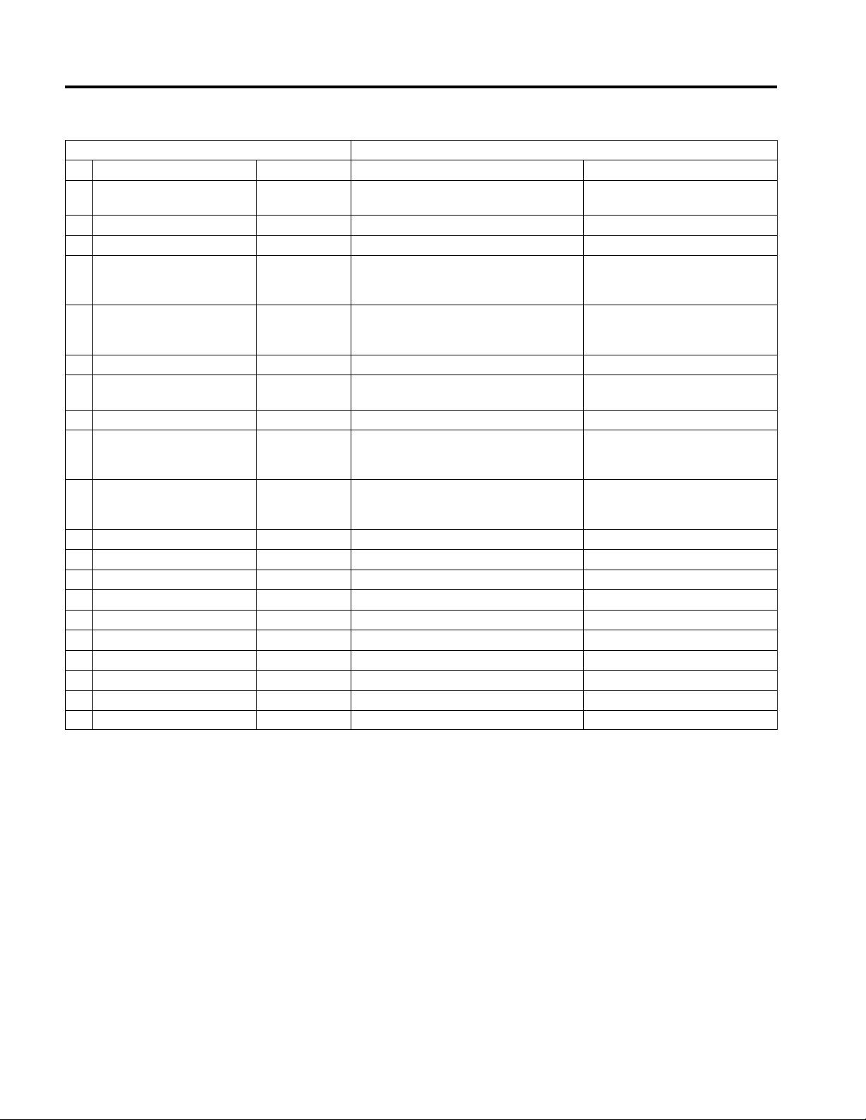
4. DIAGNOSTIC TROUBLE AND CHECK ITEMS
Diagnosis Warning Electronic control unit countermeasure(s) in the case of
code Fault location lamp failure (back-up mode) Drive ability
01 Normal — — ●
03 Pre-stroke actuator Amber Provides control with “0” as correction value. ●
learning function
Sub-control rack position Amber Normal control using the main control rack position sensor ●
06 sensor
11 Governor servo Red *1 Engine stopped by the pull-down function. ×
Pre-stroke control stop engine revolution speed limit (approx-
12 Pre-stroke servo Amber imately 1800 rpm) ▲
Pre-stroke control stop engine revolution speed limit (approx-
13 Pre-stroke sensor Amber imately 1800 rpm) ▲
Back-up engine speed Amber Control using the main engine speed sensor
14 sensor ●
Calculate the engine revolution speed from the pulse count of
15 Engine speed sensor Amber the back-up engine speed sensor. ●
Both the back-up engine
14+15 sensor and the main Red Can not start the engine. ×
engine speed sensors
are faulty upon start-up.
Accelerator pedal position Control using the accelerator pedal sensor I
16 sensor II Amber ●
21 Water temperature sensor Amber Set the water temperature to 80 °C {176°F}. ●
Control rack position Switch to the sub-control rack position sensor control.
22 sensor Amber ▲
Accelerator pedal position Control using the accelerator pedal position sensor II.
24 sensor I Amber ●
Both accelerator pedal
24+16
position
sensor I and Red Set the maximum accelerator depression angle to 30 degrees ▲
accelerator pedal
position
even if the accelerator pedal is depressed
.
sensor II are faulty
31 Idling adjustment volume Amber Set to auto idling. ●
32 Boost pressure sensor Amber Set the boost pressure to 0 kpa {0 mmHg, 0 in. Hg}. ▲*2
33 RAM (ECU internal Red Do not start the engine. ×
memory circuit)
Boost temperature sensor Amber Normal control assuming the boost temperature is
41 80 °C {176 °F}. ●
45 Reverse engine Amber *1 Engine stopped by the pull-down function. ×*2
operation
65 Accelerator switch Amber Limited accelerator depressing angle (Approximately 30%) ●
*1:The pull-down function indicates the rack pull-back action. In the event
of an engine over-run or severe accident, the rack is pulled back
immediately to the no-injection direction in order to protect the engine.
●: Driveable
▲: Back-up mode driving possible
×: Undriveable
*2:Driveable if the starter switch is turned OFF once and then restarted
again.

13EB-26
TROUBLESHOOTING
Diagnosis Diagnosis code
code display Cause Remedy
condition (s)
03 Faulty timing rod, timing sleeve or other Repair or replace the injection pump
parts in the injection pump assembly. assembly. *
Faulty adjusment or pre-stroke position Repair or replace the injection pump
sensor assembly. *
Faulty engine control unit Replace the engine control unit
06 Open or short in harness wire or poor Inspect the harness and the connector
connector contact between the ÕP13EB-41
sub-control rack position sensor and the
engine control unit
Open, short, or poor connector contact in Inspect the sub-control rack position sensor
the sub-control rack position sensor ÕP13EB-35
Faulty engine control unit Replace the engine control unit
11 Open or short in harness wire or poor Inspect the harness and the connector
connector contact between the linear DC ÕP13EB-41
motor and the engine control unit
Open or shorted wire in the linear DC Inspect the linear DC motor ÕP13EB-32
motor connector
Poor adjustment of the emergency Inspect the emergency engine stop button
engine stop cable (The lever is pulled in ÕP13EB-31
the stop direction)
Faulty injection pump assembly rack Repair or replace the injection pump
movement or poor governor actuator link assembly. *
Faulty engine control unit Replace the engine control unit
12 Open or short in harness wire or poor Inspect the harness and the connector
connector contact between the pre-stroke ÕP13EB-41
actuator, pre-stroke cut relay, and
engine control unit
Open or shorted wire in the pre-stroke cut Inspect the pre-stroke cut relay
relay ÕP13EB-34
Faulty pre-stroke actuator Repair or replace the injection pump
assembly. *
Faulty timing rod, timing sleeve, etc. in Repair or replace the injection pump
the injection pump assembly assembly. *
Faulty engine control unit Replace the engine control unit
Displayed if the output
voltage of the control rack
position sensor is less
than 0.06 V or more than
3.5 V.
Displayed if the difference
between the target control
rackposition and the actual
control rack position is
± 1mm {0.039 in.}.
Displayed if the difference
between the target timing
rod angle and the actual
timing rod angle is ± 2°.
*: Contact your MFTA representative for current injection pump repair and replacement procedures.
Indicates that pre-stroke
learning function has not
been executed.

13EB-27
13EB
Displayed if the pulse
count of the main engine
speed sensor is less than
that of the back-up engine
speed sensor.
Diagnosis Diagnosis code
code display Cause Remedy
condition (s)
13 Open or short in harness wire or poor Inspect the harness and the connector
connector contact between the pre-stroke ÕP13EB-41
position sensor and the engine control
unit
Open or shorted pre-stroke position Inspect the pre-stroke actuator
sensor coil ÕP13EB-32
Faulty engine control unit Replace the engine control unit
14 Open or short in harness wire or poor Inspect the harness and the connector
connector contact between the back-up ÕP13EB-41
engine speed sensor and the engine
control unit
Faulty back-up engine speed sensor Repair or replace the injection pump
assembly. *
Faulty engine control unit Replace the engine control unit
15 Open or short in harness wire or poor Inspect the harness and the connector
connector contact between the speed ÕP13EB-41
sensor and the engine control unit
Open or shorted wire or improperly Inspect the engine speed sensor main unit
assembled coil in the engine speed ÕP13EB-33
sensor main unit
Faulty engine control unit Replace the engine control unit
16 Open or short in harness wire or poor • Inspect the accelerator position sensor
connector contact between the using Multi-Use Tester-II ÕP13EB-30
accelerator pedal position sensor II and • Inspect the harness and the connector
the engine control unit ÕP13EB-41
Internal malfunction or faulty adjustment • Inspect the accelerator pedal position
of the lever portion of the accelerator sensor ÕP13EB-30
pedal position sensor II • Inspect the accelerator pedal position
sensor using Multi-Use Tester-II
ÕP13EB-30
Faulty engine control unit Replace the engine control unit
21 Open or short in harness wire or poor Inspect the harness and the connector
— connector contact between the coolant ÕP13EB-41
temperature sensor and the engine
control unit
Faulty coolant temperature sensor • Inspect the coolant temperature sensor
ÕP13EB-35
• Inspect the coolant temperature sensor
using Multi-Use Tester-II ÕP13EB-30
Faulty engine control unit Replace the engine control unit
Displayed if the output
voltage of the pre-stroke
position sensor is less
than 0.9 V or more than
3.4 V.
Displayed if the pulse
count of the back-up
engine speed sensor is
less than that of the main
engine speed sensor.
Displayed if the output
voltage of the accelerator
pedal position sensor is
less than 0.5 V or more
than 4.5 V.
*: Contact your MFTA representative for current injection pump repair and replacement procedures.

13EB-28
TROUBLESHOOTING
Diagnosis Diagnosis code
code display Cause Remedy
condition (s)
22 Open or short in harness wire or poor Inspect the harness and the connector
connector contact between the control ÕP13EB-41
rack position sensor and the engine
control unit
Open or shorted wire in the coil or poor • Inspect the control rack position sensor
control rack position sensor contact ÕP13EB-32
• Inspect the control rack position sensor
using Multi-Use Tester-II ÕP13EB-30
Faulty movement of the injection pump Repair or replace the injection pump
assembly control hook or poor governor assembly. *
actuator link.
Faulty engine control unit Replace the engine control unit
24 Open or short in harness wire or poor • Inspect the accelerator position
connector contact between the sensor using Multi-Use Tester-II
accelerator pedal position sensor and ÕP13EB-30
the engine control unit • Inspect the harness and the connector
ÕP13EB-41
Internal malfunction or poor adjustment • Inspect the accelerator position sensor I
of the accelerator pedal position sensor I ÕP13EB-30
lever
Faulty engine control unit Replace the engine control unit
31 Stuck idling speed adjustment potentio- Reset the knob to PUSH or PULL
meter knob (between PUSH and PULL)
Open or short in harness wire or poor Inspect the harness and the connector
connector contact between the idling ÕP13EB-41
speed adjustment potentiometer and the
engine control unit
Open wire in the switch portion of the Inspect the idling speed adjustment
idling speed adjustment potentiometer potentiometer ÕP13EB-34
or faulty internal movement
Faulty engine control unit Replace the engine control unit
32 Open or short in harness wire or poor Inspect the harness and the connector
connector contact between the boost ÕP13EB-41
pressure sensor and the engine
control unit
Internal malfunction of boost pressure • Inspect the boost pressure sensor using
sensor Multi-Use Tester-II ÕP13EB-30
• Inspect the boost pressure sensor
ÕP13EB-36
Clogged boost hose or faulty assembly Inspect the boost hose
Faulty engine control unit Replace the engine control unit
Displayed if the output
voltage of the control rack
position sensor I is less
than 0.5 V or more than
4.5 V.
Displayed if the output
voltage of the accelerator
pedal position sensor I is
less than 0.5 V or more
than 4.5 V.
Displayed if the output
voltage of the idling
adjustment volume is less
than 0.6 V or mor than
4.6 V.
Displayed if the output
voltage of the boost
pressure sensor is less
than 0.5 V or more than
4.8 V.
*: Contact your MFTA representative for current injection pumprepair and replacement procedures.

13EB-29
13EB
Diagnosis Diagnosis code
code display Cause Remedy
condition (s)
33 Faulty engine control main unit In order to reset the engine control unit,
temporarily turn the starter switch OFF and
erase the diagnostic codes by opening the
memory clear switch Õ P13EB-24
Replace the engine control unit if the
diagnostic codes persist after performing
the above procedure
41 Open or short in harness wire and poor Inspect the harness and the connector
connector contact between the boost ÕP13EB-41
temperature sensor and the engine
control unit
Open or shorted wire or poor assembly • Inspect the boost temperature sensor
of the boost temperature sensor coil ÕP13EB-37
• Inspect the boost temperature sensor
using Multi-Use Tester-II ÕP13EB-30
Faulty engine control unit Replace the engine control unit
45 Faulty phase of engine speed sensor • Inspect the engine speed sensor
— and backup engine speed sensor ÕP13EB-33
• Repair or replace the injection pump
assembly. *
65 Faulty accelerator switch Open or short in harness wire or poor Inspect the harness and the connector
connector contact between the accelera- ÕP13EB-41
tor switch and the engine control unit
Open or shorted wire in the accelerator Inspect the accelerator switch
switch (Accelerator switch is built in the accelerator
pedal position switch.) ÕP13EB-31
Faulty engine control unit Replace the engine control unit
Displayed if the engine
control unit is faulty.
Displayed if the output
voltage of the boost
temperature sensor is
more than 4.9 V.
*: Contact your MFTA representative for current injection pump repair and replacement procedures.
13EB-30
TROUBLESHOOTING
5. Service of Multi-Use Tester II
Multi-Use Tester-II display Inspection procedure
No. Data signal Type of data Inspection condition Evaluation criterion
11 ENGINE SPEED ❙❙❙❙. rpm Gradual acceleration (during engine Synchronization with tachometer
operation)
12 TARGET RACK ❙❙.❙❙ mm Starter switch ON 3 mm
13 REAL RACK ❙❙.❙❙ mm Starter switch ON 3 mm
Accelerator pedal gradually depressed
14 ACCEL. VOLT ❙.❙❙❙ V from throttle-fully-closed to throttle-fully- 1 to 3 V
open position
Engine cold Same as ambient temperature
15 WATER TEMP ❙❙❙.❙ °F Engine warming up Gradual increase
Engine stopped after warmup Gradual decrease
16 BOOST PRESS ❙❙❙❙. mmHg Engine running at high idling speed 270 mmHg or higher
17 PS ANG. DIFF. ❙❙.❙❙ deg 400 < Ne 2,000 –5.5° or greater
Ne: Engine speed 5.5° or smaller
18 SUPPLY VOLT ❙❙.❙❙ V Starter switch ON 7 to 14 V
Throttle completely closed 0 %
19 ACCEL. STROKE ❙❙❙.❙% Pedal gradually depressed Gradual increase
Throttle completely open 100 %
Engine cold Same as ambient temperature
20 BOOST TEMP ❙❙❙.❙ °F Engine warming up Gradual increase
Engine stopped after warmup Gradual decrease
21 START SIG ON/OFF Engine cranked using starter switch ON
33 ACCEL. SW ON/OFF Accelerator pedal depressed OFF
34 DIAGNOSIS SW ON/OFF Diagnosis switch turned ON/OFF ON/OFF
35 DIAG. RESET SW ON/OFF Memory clear switch turned ON/OFF ON/OFF
37 CLUTCH SW ON/OFF Clutch pedal depressed ON
38 NEUTRAL SW ON/OFF Transmission in neutral OFF
42 EXH. BRAKE SW ON/OFF Switch ON ON
51 A/C SW ON/OFF Air conditioner switch turned ON or OFF ON/OFF
61 EXH. BRAKE SIG ON/OFF Exhaust brake operating ON
75 IDLE UP CNCL ON/OFF Idle up prohibited (other than N range) ON
VII

13EB-31
13EB
1Idling speed adjustment potentiometer
2Relay box
3Exhaust brake cut relay < A/T >
Transmission neutral relay < M/T >
4Pre-stroke cut relay
5Exhaust brake relay < M/T >
6Sub control rack position sensor
7Engine coolant temperature sensor
8Pre-stroke actuator
9Boost pressure sensor
10 Control rack position sensor
11 Backup engine speed sensor
12 Linear DC motor
13 Engine speed sensor
14 Exhaust brake 3-way magnetic valve
15 Transmission neutral switch < M/T >
16 Boost temperature sensor
17 Emergency engine stop button
18 Clutch pedal switch
19 Fuel injection rate adjustment resistor
*a: Electronic governor
*b: Injection pump
M/T : Manual transmission
A/T : Automatic transmission
31550
9*a
*b
< Left side of engine >
2
INSPECTION OF ELECTRICAL EQUIPMENT

13EB-32
INSPECTION OF ELECTRICAL EQUIPMENT
Location Maintenance item Standard value Limit Remedy
Output voltage of idling
speed adjustment Knob pulled 1 to 3 V —
potentiometer
1
2
–
3
Replace
Knob 3.6 to 4.3 V —
pushed
1
–
4
92.5 to 101.5 Ω—
6Resistances of sub control
1
–
3
92.5 to 101.5 Ω—
rack position sensor
3
–
4
185 to 203 Ω—
Engine coolant Between terminal 20°C {68°F} (3.25 kΩ)—
7temperature sensor and body 40°C {104°F} (1.5 kΩ) — Replace
60°C {140°F} (620±62 Ω) —
Resistance of
2
–
3
5.5 to 6.1Ω—
8pre-stroke actuator
1
–
3
11.0 to 12.2 Ω—
(measured at
1
–
2
5.5 to 6.1Ω—
connector)
4
–
5
0.9 to 1.3 Ω
< Connector: 3 pin >
3
(3 pin) –
4
(10 pin)
3
(10 pin) –
4
(10 pin) 31.5 to 36.5 Ω—
< Connector: 10 pin > G–C
3
(3 pin) –
9
(10 pin)
3
(10 pin) – 18.0 to 21.0 Ω
< Governor actuator >
9
(10 pin) —
10
G–F
4
(10 pin) –
9
(10 pin)
13.5 to 15.5 Ω—
C–F
Service standards Unit : mm {in.}
Resistances
of control
rack position
sensor
24816
16165
16160
13725
13714
A
B
E
D
FG
C
16184
Repair or replace
the injection pump
assembly. *
Repair or replace
the injection pump
assembly. *
Repair or replace
the injection pump
assembly. *
The values in ( ) are reference values
*: Contact your MFTA representative for current injection pump repair and replacement procedures.

13EB-33
13EB
Location Maintenance item Standard value Limit Remedy
< Connector: 3 pin >
< Connector: 10 pin >
12 < Governor actuator >
Resistance of
13 engine speed sensor
1
–
2
2.1 to 2.5 Ω— Replace
(at 25°C {77°F})
14 Minimum operating voltage of 11 V or more — Replace
3-way magnetic valve
Resistance valve of boost 0°C {32°F} 5880±588 Ω—
16 temperature sensor 20°C {68°F} 2455±245 Ω— Replace
80°C {176°F} 322±32 Ω—
ÊTightening torque Unit : N·m {ft.lbs, kgf·m}
Location Parts to be tightened Tightening torque Remarks
7Coolant temperature sensor 34 ± 6.9 {25±5, 3.5±0.7} —
13 Lock nut of engine speed sensor 24 to 35 {17 to 26, 2.4 to 3.6} —
24816
16165
16160
G
A
B
F
C
D
E
Resistances
of linear DC
motor 9.0 to 9.8 Ω—
321
14013
14318
Unit : mm {in.}
Repair or
replace the in-
jection pump
assembly. *
*: Contact your MFTA representative for current injection pump repair and replacement procedures.
2
(3 pin) –
1
(3 pin)
2
(3 pin) –
2
(10 pin)
1
(10 pin) –
2
(10 pin)
1
(10 pin) –
1
(3 pin)
A– B

13EB-34
INSPECTION OF ELECTRICAL EQUIPMENT
Connector terminal
Accelerator pedal position sensor
Item inspection harness
1
: Power
2
: GND (–)
3
: Output(+)
supply (+)
Output voltage with
knob pulled –+
Output voltage with
knob pushed
Output characteristics
02779
02778
1A
C
B
C
1
23
4.3
3.6
3
1
0300°
Angle of rotation
Output voltage (V)
PUSH
PULL
}
}
1
Inspection of idling speed adjustment potentiometer
• Disconnect the harness Aof the idling speed adjustment potentiometer
1from the cab-side harness B. Then, connect an inspection harness
Cbetween harnesses Aand B. (The inspection harness must be
made specially for this procedure.)
• Turn the starter switch to the ON position.
• Check the output voltages of the idling speed adjustment
potentiometer 1in accordance with the following table.
• If the output voltages are out of specification, replace the idling speed
adjustment potentiometer 1.
◆ Service procedure
07387 +–
+
2
1
3
4
4
3
1
2
–+
–
34
Inspection of pre-stroke cut relay and exhaust brake
cut relay (normally-closed type with 4-pin connector)
• Perform continuity checks in accordance with the following table.
1234
Not energized
Energized
:Continuity exists between terminals.
:Terminals across which 12 V DC is applied.
:Continuity no longer exists between terminals.
• Replace the relay if any abnormality is evident.
1.0 - 3.0
3.6 - 4.3

13EB-35
13EB
1234
No current
Current
07142
+–
+–
5
Inspection of exhaust brake relay (Open type 4 pin)
• Follow the table below to inspect continuity :
: There is continuity between terminal and .
: Indicates that 12 volts DC is applied to the line between
the terminals.
• If any fault is found, replace the relay.
2
1
3
4
–
+
431
2
13722
1
13799
21
43
6
6
Inspection of sub control rack position sensor
• Measure the resistances between the following terminals :
1
and
4
;
1
and
3
;
3
and
4
.
• If any resistance is out of specification, replace the sub control rack
position sensor 6.
• Have replacement performed by the nearest MFTA Dealer.
7
Inspection of engine water temperature sensor
• Put the engine water temperature sensor 7in a container of engine oil.
• Heat the oil to each of the specified temperatures. Stir the oil to ensure
that it heats up evenly.
• At each of the specified temperatures, measure the resistance be-
tween the terminal
1
and body of the engine water temperature
sensor 7.
• If the measurements are out of specification, replace the engine water
temperature sensor.
Item Standard value Limit Remedy
(reference values)
Engine coolant Between 20°C {68°F} (3.25 k) ohms —
temperature Terminal 40°C {104°F} (1.5k) ohms — Replace
sensor and body 60°C {140°F} (650±62k) ohms —

13EB-36
INSPECTION OF ELECTRICAL EQUIPMENT
P31493
F
Inspection of control rack position sensor
Perform the following inspections. If any abnormality is evident, have
inspection and repair performed by the nearest MFTA.
●Measurements on connectors
Measure resistances between terminals as specified in the standard
table.
13790
3
62
51
4
8
Inspection of pre-stroke actuator
Perform the following inspections. If any abnormality is evident, have
inspection and repair performed by the nearest MFTA Dealer.
CAUTION –
The pre-stroke actuator 8 must be inspected when the engine is
cold.
(1) Measurements on connectors
Measure the resistance between terminals
2
and
3
;
1
and
3
;
1
and
2
;
4
and
5
.
9
Inspection of boost pressure sensor
• Mount pressure gauge Afor boost pressure measurement as shown
in the diagram.
• Connect the Multi-Use Tester-II . Õ P13EB-22.
• Set the Multi-Use Tester-II for boost pressure measurement
• Start the engine. Compare the value displayed on the Multi-Use
Tester-II and the value indicated by pressure gauge A. If the values
are different, replace boost pressure sensor 9.
B: To inlet manifold.
20580
AB
6
H
Inspection of linear DC motor
Perform the following inspections. If any abnormality is evident, have
inspection and repair performed by the nearest MFTA Dealer.
(1) Measurements on connectors
Measure resistances between terminals as specified in the standard
table.
P31493
54321
10 9 8 7 6
21
3
54321
10 9 8 7 6
21
3
This manual suits for next models
4
Other Mitsubishi Fuso Truck manuals

Popular Truck manuals by other brands


Pfaff
Pfaff SILVERLINE I HU W-20 SL Translated Operating Instructions

Peterbilt
Peterbilt 579 Operator's manual

Navistar
Navistar ProStar+ Operation and maintenance manual

Chevrolet
Chevrolet 10-30 1967 Series Owner's and driver's manual

Hoppe
Hoppe AUDIO MINI Installation instructions & owner's manual

BorMann
BorMann PRO BWR2515 manual