Indicators, Gauges and Switches (BD2G)
OK
monitor test switch
.. When this switch
is
pushed
with starter switch ON:
Alternator
not
charging
and engine oil pressure
warning lamps glow (with
engine stopped).
Ba
ttery
electrolyte level
and air cleaner element
warning lamps glow (with
engine running).
Battery switch
@i·.L-.---"------<.J
-§o-
Lighting
~I"
switch
Twist
~
1st 2nd
position
position
501959
502666
Position
Head
lamps
Working
lamp
Instrument
panel lamp
rop)
$
Water
temperature
gauge Overheat
.--
______
(red) .
Normal
TEMP
(green)
50
1889
Service meter
Every 6 minutes
dial advances
1
hour
one number.
501887
00
502665
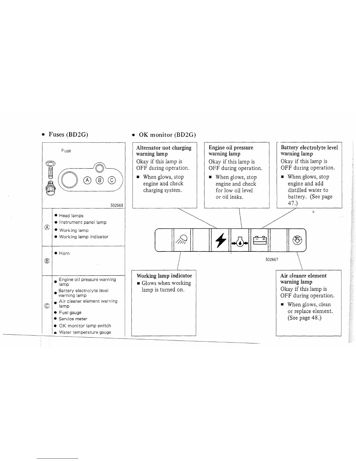
OK
monitor
..
When any lamp glows
during operation, stop
machine soon and check
for cause. (See page 16.)
I Fuel gauge
Empty
(red)
Full
(green)
501888
1st 2nd
(l)
Starter switch
Twist
'Twist
Glow plug indicator
Glows when starter switch
is
I
turned to HEAT.
".
START
HEAT
OFF
ON
START
Heat engine.
Insert
or
pull
out
key.
Keep engine
running.
Start
engine.
501956