10
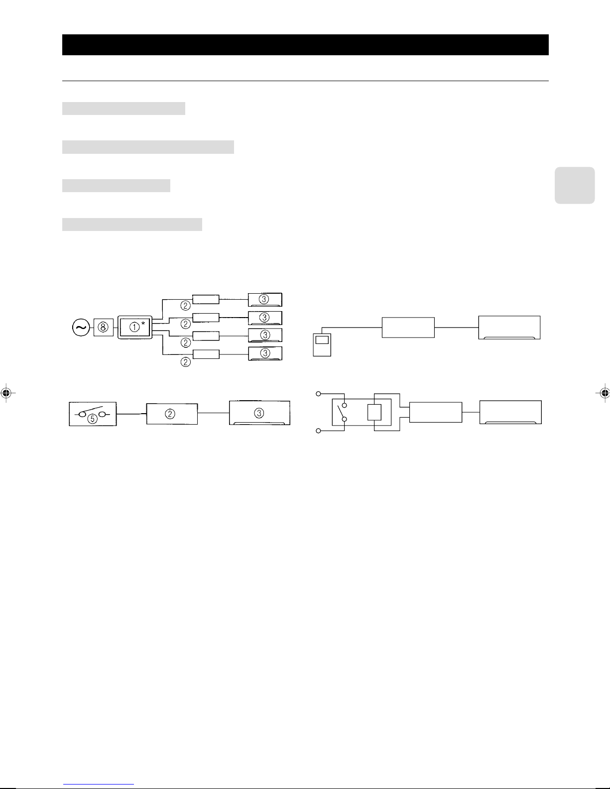
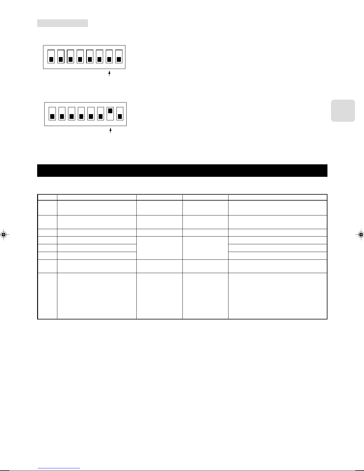
Remote control (CN591) mode switch
SW 500 Functions
Do not use the CN591 remote control
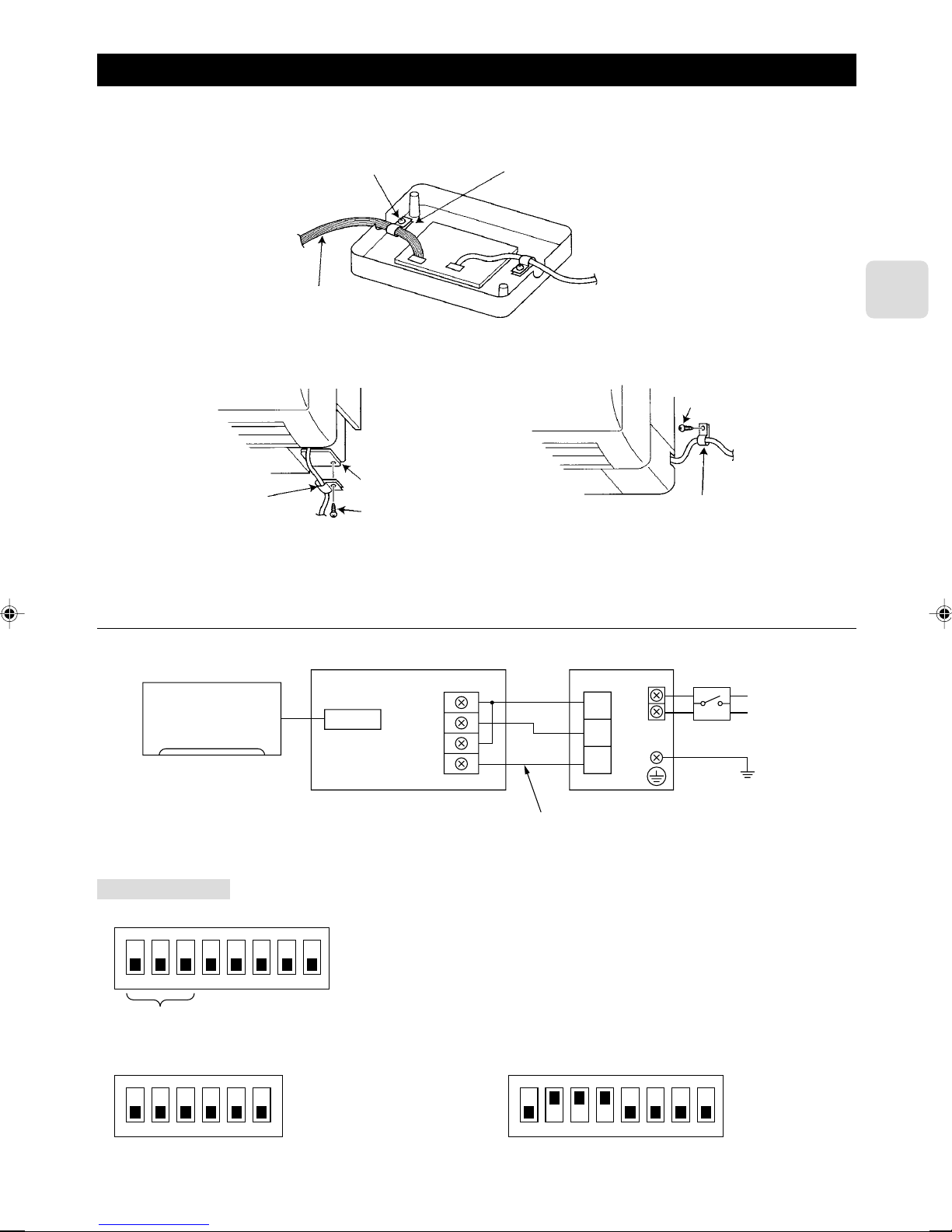
ON/OFF Prohibited/Allowed mode 1
ON/OFF Prohibited/Allowed mode 2
(level input)
ON/OFF Prohibited/Allowed mode 3
(pulse input)
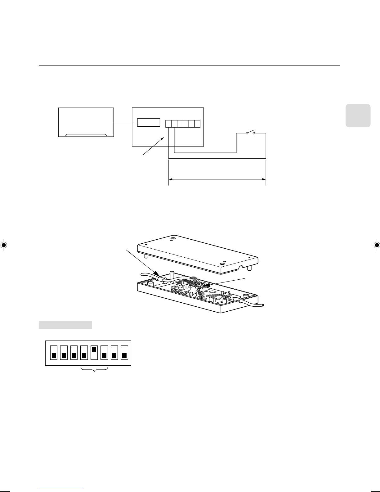
Coin timer mode 1 (for a no-voltage
contact point a)
Coin timer mode 2 (for a no-voltage
contact point b)
Cooling-Heating/Temperature settings
mode 1 (3 temperature patterns)
Cooling-Heating/Temperature settings
mode 2 (8 temperature patterns)
Operating Details
–
Manual operations prohibited when CN591 No. 1 and No. 3 are closed, permitted
when open.
Only when No. 1 and No. 3 are closed and manual operations are prohibited.
On when CN591 No. 1 and No. 2 are closed, off when open.
(Cannot be operated from the remote control when manual operations are pro-
hibited. Only valid when operated from the CN591.)
On when CN591 No. 1 and No. 2 are closed, off when open.
Manual operations prohibited when No. 1 and No. 3 are closed, permitted when
open.
(Cannot be operated from the remote control when manual operations are pro-
hibited. Only valid when operated from the CN591.)
On when CN591 No. 1 and No. 2 are closed, off when No. 1 and No. 3 are closed.
Manual operations prohibited when No. 1 and No. 4 are closed, and permitted
when No. 1 and No. 5 are closed.
(Same as when they are open.)
Permitted and on when CN591 No. 1 and No. 2 are closed, manual operations
prohibited and off when open.
(When permitted, the unit can be operated from the remote control.)
Manual operations prohibited and off when CN591 No. 1 and No. 2 are closed,
permitted and on when open.
(When permitted, the unit can be operated from the remote control.)
On when CN591 No. 1 and No. 2 are closed, off when open.
When No. 1 and No. 3 are closed 20 °C
When No. 1 and No. 4 are closed 24 °C
When No. 1 and No. 5 are closed 28 °C
(When multiple switches No. 3, 4, and 5 are closed, the highest temperature will
be selected.)
Heat when No. 1 and No. 6 are closed, cool when open.
(Remote control operations are valid as always.)
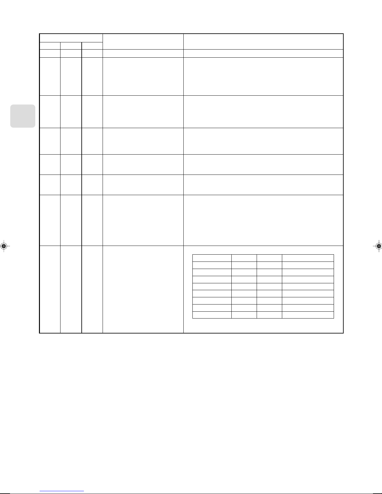
On when CN591 No. 1 and No. 2 are closed, off when open.
No. 1 and No. 3 No. 4 No. 5 Temperature settings
Open Open Open 16 °C
Closed Open Open 18 °C
Open Closed Open 20 °C
Closed Closed Open 22 °C
Open Open Closed 24 °C
Closed Open Closed 26 °C
Open Closed Closed 28 °C
Closed Closed Closed 30 °C
Heat when No. 1 and No. 6 are closed, cool when open.
(Remote control operations are valid as always.)
No. 5
OFF
OFF
ON
ON
OFF
OFF
ON
ON
No. 6
OFF
ON
OFF
ON
OFF
ON
OFF
ON
No. 4
OFF
OFF
OFF
OFF
ON
ON
ON
ON