Autorisierungsverfahren
7/128
2 Autorisierungsverfahren
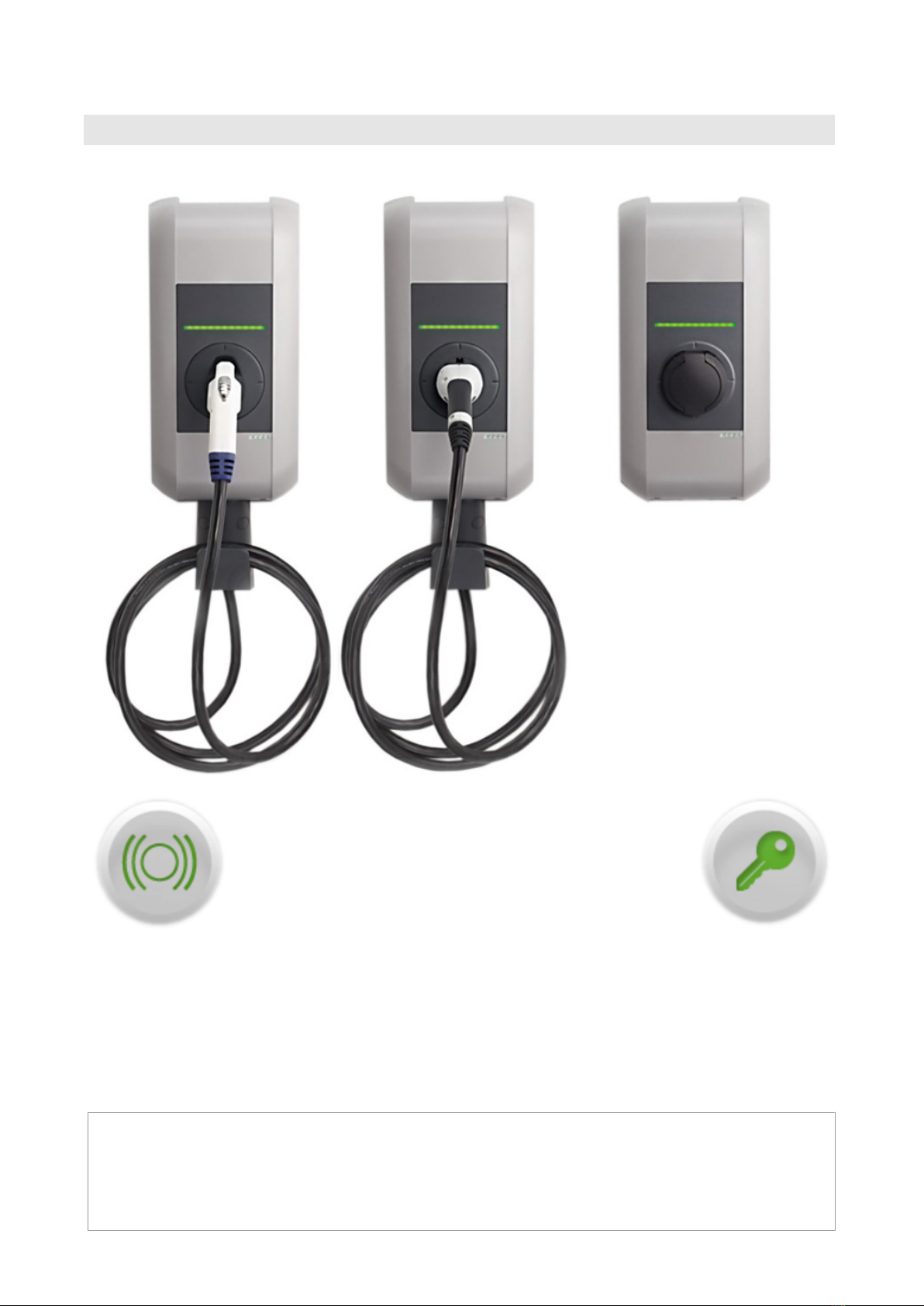
2.1 Status LED
Status LED - Segmente…
Die Status LED informiert über den aktuellen Betriebs-
zustand der Stromladestation und besteht aus 4 Seg-
menten (S1 bis S4), die gemeinsam oder einzeln
leuchten können.
Alle Segmente können in unterschiedlichen Farben
leuchten oder blinken.
Wenn nicht anders angegeben, leuchten alle 4 Seg-
mente gemeinsam.
Status LED Funktion
Blinkt langsam
alle 3 Sekun-
den
grün Betriebsbereit (Ladekabel ist noch nicht auf beiden Seiten angesteckt;
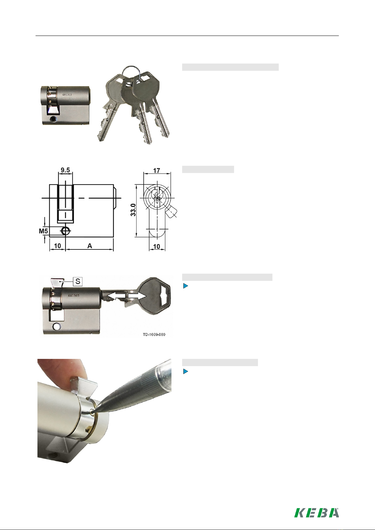
optional: die Ladestation wurde durch Schlüsselschalter oder RFID Karte
korrekt autorisiert)
blau Autorisierung ist erforderlich (Stromladestation wurde noch nicht kor-
rekt autorisiert; Autorisierung mit RFID, Schlüsselschalter oder externer
Freigabe erforderlich)
Leuchtet per-
manent
grün Fertig zum Laden (Ladekabel ist auf beiden Seiten angesteckt und verrie-
gelt)
blau Fertig zum Laden mit ISO15118 (Ladekabel ist auf beiden Seiten ange-
steckt und verriegelt)
Externe Freigabe noch erforderlich (Autorisierung mit RFID oder
Schlüsselschalter durchgeführt; Fahrzeug korrekt verbunden; Externe
Freigabe am Freigabeeingang noch erforderlich)
Blinkt jede Se-
kunde
grün Ladevorgang wird durchgeführt (gilt für „EN 61851 Mode 3“ Ladevor-
gang)
blau Ladevorgang wird durchgeführt (gilt für „ISO15118“ Ladevorgang)
Leuchtet nach dem Anstecken
kurz orange
Warten auf Verriegelung (Ladekabel wurde angesteckt und es wird ver-
sucht, den Stecker zu verriegeln)
Grüne LED erlischt kurz alle 3
Sekunden
Warten auf Abstecken (Ladevorgang beendet, Fahrzeug abgesteckt)
Blinkt langsam alle 5 Sekun-
den orange
Temperaturüberschreitung (Ladevorgang vorübergehend unterbrochen
und wird nach Abkühlung wieder fortgesetzt)