Miyachi Unitek 100DP User manual

USER'S MANUAL 990-295
Revision B June 2007
100DP/300DP DUAL PULSE
STORED ENERGY
RESISTANCE WELDING POWER SUPPLIES
Model Stock No.
100DP/115 1-293-01
100DP/230 1-293-01-01
300DP/115 1-294-01
300DP/230 1-294-01-01

100DP/300DP DUAL PULSE RESISTANCE WELDING POWER SUPPLY
ii 990-295
Copyright © 2005 Miyachi Unitek Corporation
The engineering designs, drawings and data contained herein are the
proprietary work of Miyachi Unitek Corporation and may not be
reproduced, copied, exhibited or otherwise used without the written
authorization of Miyachi Unitek Corporation.
Printed in the United States of America.
Revision Record
Revision EO Date Basis of Revision
A 20633 12/05 None. Original edition.
B 21448 6/07 Added open load detection feature

100DP/300DP DUAL PULSE RESISTANCE WELDING POWER SUPPLY
990-295 iii
CONTENTS
Page
Revision Record ........................................................................................................................................ ii
Contact Us .........................................................................................................................................v
Safety Notes ....................................................................................................................................... vi
Chapter 1. Description
Section I: Features .................................................................................................................................. 1-1
Features ..................................................................................................................................... 1-1
Description ..................................................................................................................................... 1-2
Section III: Major Components ............................................................................................................. 1-4
Major Components ........................................................................................................................... 1-3
Front Panel Display and Display Controls ............................................................................... 1-3
Schedule Number and Chain Switch ........................................................................................ 1-4
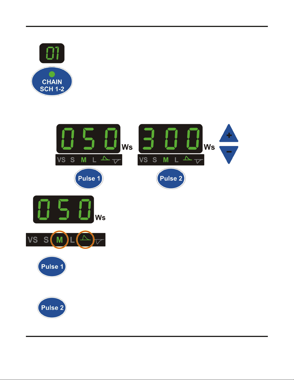
Energy and Pulse Indicators, Pulse Edit Buttons, Up/Down Buttons ...................................... 1-4
Polarity Select ........................................................................................................................... 1-7
Charge Monitor ........................................................................................................................ 1-7
WELD/NO WELD Switch ....................................................................................................... 1-7
Emergency Stop Switch Operation .................................................................................................. 1-7
Chapter 2. Installation and Setup
Section I: Installation ............................................................................................................................. 2-1
Unpacking ..................................................................................................................................... 2-1
Space Requirements ......................................................................................................................... 2-1
Utilities ..................................................................................................................................... 2-2
Power ..................................................................................................................................... 2-2
Compressed Air and Cooling Water ......................................................................................... 2-2
Input Logic Configuration ............................................................................................................... 2-2
Section II: Setup ..................................................................................................................................... 2-3
Connections to External Equipment ................................................................................................ 2-3
Weld Head Connections .................................................................................................................. 2-4
Foot Pedal-Actuated Weld Head Connection .................................................................................. 2-5
EZ-AIR Weld Head Connections ..................................................................................................... 2-6
Chapter 3. Operation
Section I: Introduction ........................................................................................................................... 3-1
Before You Start .............................................................................................................................. 3-1
Pre-Operational Checks ................................................................................................................... 3-1
Connections .............................................................................................................................. 3-1
Power ..................................................................................................................................... 3-1
Compressed Air ........................................................................................................................ 3-1
Adjust Buzzer Loudness .................................................................................................................. 3-1

100DP/300DP DUAL PULSE RESISTANCE WELDING POWER SUPPLY
iv 990-295
CONTENTS (Continued)
Page
Chapter 3. Operation (Continued)
Initial Setup ..................................................................................................................................... 3-2
Section II. Operation .............................................................................................................................. 3-3
Using Existing Weld Schedules ....................................................................................................... 3-3
Modify Weld Schedules .................................................................................................................. 3-3
Using the WELDS Counter ............................................................................................................. 3-4
Using LIMIT Set .............................................................................................................................. 3-4
Chain Schedules 1 & 2 .................................................................................................................... 3-5
Dual Weld Head Operation ............................................................................................................. 3-5
Programming Lock ........................................................................................................................... 3-5
Schedule Lock .................................................................................................................................. 3-5
Chapter 4. Maintenance
Section I. Troubleshooting ..................................................................................................................... 4-1
Troubleshooting ............................................................................................................................... 4-1
Error Codes .................................................................................................................................... 4-2
Section III. Maintenance ........................................................................................................................ 4-4
Calibration ..................................................................................................................................... 4-4
Electrode Maintenance .................................................................................................................... 4-4
Parts Replacement ........................................................................................................................... 4-4
Section IV. Repair Service ..................................................................................................................... 4-5
Appendix A. Technical Specifications ............................................................................................... A-1
Appendix B. Electrical and Data Connections ..................................................................................B-1
Appendix C. System Timing ...............................................................................................................C-1
Appendix D. The Basics of Resistance Welding ............................................................................... D-1
Appendix E. Quality Resistance Welding Solutions: Defining the Optimum Process .................E-1

100DP/300DP DUAL PULSE RESISTANCE WELDING POWER SUPPLY
990-295 v
CONTACT US
Thank you for purchasing a Miyachi Unitek™ Resistance Welding System Control.
Upon receipt of your equipment, please thoroughly inspect it for shipping damage prior to its
installation. Should there be any damage, please immediately contact the shipping company to file a
claim, and notify Miyachi Unitek at:
1820 South Myrtle Avenue
P.O. Box 5033
Monrovia, CA 91017-7133
Telephone: (626) 303-5676
FAX: (626) 358-8048
e-mail: [email protected]
The purpose of this manual is to supply operating and maintenance personnel with the information
needed to properly and safely operate and maintain the Miyachi Unitek™ 100DP and 300DP Resistance
Welding System Control.
We have made every effort to ensure that the information in this manual is accurate and adequate.
If you have any questions, or if you have suggestions to improve this manual, please contact us at the
above location/numbers.
Miyachi Unitek Corporation is not responsible for any loss due to improper use of this product.

100DP/300DP DUAL PULSE RESISTANCE WELDING POWER SUPPLY
vi 990-295
SAFETY NOTES
DANGER
•Lethal voltages exist within this unit.Never perform any maintenance inside this unit.
•Never perform any welding operation without wearing protective safety glasses.
This instruction manual describes how to operate, maintain and service the 100DP and 300DP
Resistance Welding Power Supplies, and provides instructions relating to its safe use. A separate
manual provides similar information for the weld head used in conjunction with the power supply.
Procedures described in these manuals must be performed, as detailed, by qualified and trained
personnel.
For safety, and to effectively take advantage of the full capabilities of the weld head and power supply,
please read these instruction manuals before attempting to use them.
Procedures other than those described in these manuals or not performed as prescribed in them, may
expose personnel to electrical or burn hazards.
After reading these manuals, retain them for future reference when any questions arise regarding the
proper and safe operation of the power supply.
Please note the following conventions used in this manual:
WARNING: Comments marked this way warn the reader of conditions which might result in
immediate death or serious injury.
CAUTION: Comments marked this way warn the reader of conditions which might result in either
damage to the equipment, or injury to the individual.

100DP/300DP DUAL PULSE RESISTANCE WELDING POWER SUPPLY
990-295 1-1
CHAPTER 1
Description
Section I: Features
Features
The Miyachi Unitek 100DP/300DP Dual Pulse Resistance Welding Power Supply precisely controls
welding energy and weld head timing.
•Multi-function microprocessor control
provides repeatable process control and is
compatible with air or manually actuated
weld heads. Facilitates multiple applications
at a single work-station and protects weld
schedules from changes by unauthorized
personnel.
•Dual pulse welding eliminates weld splash.
Improves weld quality, especially when
welding plated materials.
•Alternating polarity allows the user to set up
a pulse to change from positive to negative
polarity each time the welder is fired. This
allows the user to equalize the wear between
two electrodes in many parallel gap welding
processes.
•Two air valve drivers are provided to
sequentially control two separate air operated
weld heads, if desired. As shipped, Air
Valve Driver 1 is configured to drive a 24
VAC weld head, but can be reconfigured to
drive a 24VDC weld head instead. Air Valve
Driver 2 can only drive a 24VDC weld head.
•Three relays provide signals for when the unit is ready to weld, when a weld is completed, and when
the weld counter has reached its preset limit.
•Remote schedule selection simplifies use in automated systems. A CONTROL SIGNALS connector
accepts remote control signals for Emergency Stop, Remote Weld Inhibit, and Remote Weld
Schedule Selection.
•The chain schedule feature allows Schedule 1 and Schedule 2 to be chained together.
•Schedule protection and system security features protects weld schedules from changes by
unauthorized personnel.

CHAPTER 1: DESCRIPTION
100DP/300DP DUAL PULSE RESISTANCE WELDING POWER SUPPLY
1-2 990-295
•The schedule lock feature allows you to restrict welding to one selected weld schedule.
•The digital display allows operators to set welding energy accurately and quickly.
•The Power Supply is compatible with manually actuated weld heads and air actuated heads with 1-
level or 2-level foot switches.
•The Power Supply is compatible with force fired and non-force fired weld heads. Squeeze (delay)
time is adjustable from 0 to 2.999 seconds.
•A built-in weld counter allows you to control events which are a function of the number of welds
made.
•The firing circuit uses single pole, double pole or optical firing (pressure) switches.
•The energy monitor and lockout helps prevent poor welds caused by firing the power supply before
the capacitor bank is properly charged or discharged.
•The line failure turndown safety feature discharges the capacitor bank when input power is
interrupted.
•The Power Supply is protected from radio frequency interference and electromagnetic interference,
resulting in reliable operation even in high electrical noise environments. Input switch debounce
circuitry eliminates false triggering.
Detailed instructions on using these features are located in Chapter 3, Operating Instructions.
NOTE: For the rest of this manual, the Miyachi Unitek 100DP/300DP Dual Pulse Resistance
Welding Power Supply will simply be referred to as the Power Supply.
Description
The Power Supplies are versatile, 100 Watt-second and 300 Watt-second stored energy, capacitor
discharge, dual pulse power supplies which can effectively solve most precision, small parts,
resistance welding problems.
You can program up to 15 weld schedules and save them in memory. A built-in schedule protection
feature protects weld schedules from unauthorized or inadvertent changes. The exclusive charge
monitor and firing lockout feature guarantees that weld quality is independent of line voltage
fluctuations and the speed at which the power supply is operated.
Dual pulse welding improves weld quality and eliminates weld splash. Dual pulse means each weld is
performed with two pulses with independent energy levels and independent polarity. The first pulse
displaces the plating or contamination and reforms the surface so that it is in intimate contact with the
electrode. The second pulse welds the base metals.
The remote schedule feature allows the Power Supplies to reliably select weld schedules in automated
applications.
The Power Supplies can be used with manual, user actuated, or air actuated weld heads. The units are
designed to operate at either 100-120VAC or 200-240VAC, 50/60 Hz.

CHAPTER 1: DESCRIPTION
100DP/300DP DUAL PULSE RESISTANCE WELDING POWER SUPPLY
990-295 1-3
Section II: Major Components
Major Components
The major components are the front panel, which contains the operator’s controls and indicators, and the
rear panel, which contains fuses, circuit breakers and power and signal connectors. The rear panel
connections are discussed in Chapter 2, Installation and Setup.
Front Panel Display and Display Controls
The front panel of the Control below shows controls and indicators. The function of each item is
described on the following pages.
Front Panel Controls

CHAPTER 1: DESCRIPTION
100DP/300DP DUAL PULSE RESISTANCE WELDING POWER SUPPLY
1-4 990-295
Schedule Number and Chain Switch
The 2-digit LED displays which welding schedule is selected for use.
The CHAIN SCH 1-2 button will “chain” Schedule 1 and Schedule 2 together,
meaning welding pulses will alternate between these two schedules. The green
light on this switch will be ON when the “chain” function is in use.
Welding will continue repeating between these schedules until you press the
CHAIN SCH 1-2 button again and the green light on the button goes OFF. Welding
will then continue from a single schedule.
Energy and Pulse Indicators •Pulse Edit Buttons •UP/DOWN Buttons
The 3-digit LED displays the energy for each pulse in Watt-
seconds (Ws).
When in the “edit” mode, this display will flash until editing is
complete.
PULSE and POLARITY indicators. These displays will light up to
indicate which pulse length and polarity has been selected for each
pulse.
Press either of these buttons for approximately 1 second to put the Power Supply
into the “edit” mode. This enables you to modify the settings for each weld
schedule.
Press the Pulse 1 button and wait for the LED to flash. When the LED flashes,
you can change the energy, pulse length, and polarity for Pulse 1. To accept the
changes, press the Pulse 1 button again and the LED will stop flashing. To exit
the “editing” mode without accepting changes, press the clear button or any
other button on the front panel.
Press the Pulse 2 button and follow the same procedures to modify Pulse 2.

CHAPTER 1: DESCRIPTION
100DP/300DP DUAL PULSE RESISTANCE WELDING POWER SUPPLY
990-295 1-5
The UP (+) and DOWN (−) buttons have two functions.
During “normal” operation, these are used to scroll up or down through the
schedule numbers in order to select a schedule. The schedule number displayed
in the 2-digit LED is the schedule selected for welding.
In the “editing” mode, these buttons will increase or decrease the values in the
PULSE 1 and PULSE 2 energy, WELDS or LIMIT SET displays.
Pulse Select
This button is only active when the Power Supply is in the “editing” mode. Press
this button repeatedly until the pulse duration you want is lit underneath the 3-
digit energy display. As shown below, the MEDIUM (M) pulse duration is selected.
NOTE: The VERY SHORT (VS) setting gives the highest peak current and
shortest duration for the energy setting. The LONG (L) setting gives the lowest
peak current and longest duration for the energy setting.
Weld Counter and Setup

CHAPTER 1: DESCRIPTION
100DP/300DP DUAL PULSE RESISTANCE WELDING POWER SUPPLY
1-6 990-295
Pressing this button causes the green LED on the button to go ON and the 6-digit
COUNTER display will show the total number of welds the Power Supply has
made since the last time it was reset to zero. This feature can be used to count the
number of welds during a particular shift or work day
Pressing this button causes the green LED on the button to go ON and the 6-digit
COUNTER display will show the LIMIT SET for the number of welds made. After
the limit is reached, the Power Supply will “beep” each time a weld is made. This
signals the Operator to take action.
Pressing this button for about 1 second causes the green LED on the button to go
ON and the 6-digit COUNTER display to blink. This allows the arrows to
increase or decrease the LIMIT SET value. Pressing this button again saves the
setting and stops the 6 digit display from blinking and saves the value.
This feature is useful for counting weld made on a set of electrodes to determine
when to change electrodes. .
When you are using the weld count, limit set, squeeze time, or hold time
functions, the time in the 6-digit COUNTER display will reset to zero when you
press and hold this button for about a second.
Depending on which button is pressed, this 6-digit display in the
COUNTER section is used to display the number of welds made (WELDS),
the limit that has been set for a set of electrodes (LIMIT SET), squeeze time
(SQZ), or the hold time (HOLD). It also displays error codes as described
in Chapter 4.
Pressing this button causes the green LED on the button to go ON and the 6-digit
COUNTER display will show the squeeze time for the current schedule. Pressing
this button for about 1 second causes the green LED on the button to go ON and
the 6-digit COUNTER display to blink. This allows the arrows to increase or
decrease the squeeze time. Pressing this button again saves the setting
Pressing this button causes the green LED on the button to go ON and the 6-digit
COUNTER display will show the hold time for the current schedule.
Pressing this button for about 1 second causes the green LED on the button to go
ON and the 6-digit COUNTER display to blink. This allows the arrows to
increase or decrease the hold time. Pressing this button again saves the setting.

CHAPTER 1: DESCRIPTION
100DP/300DP DUAL PULSE RESISTANCE WELDING POWER SUPPLY
990-295 1-7
Polarity Select
This button is only active when the Power Supply is in the “editing” mode. Press
this button repeatedly until the polarity you want is lit underneath the 3-digit
energy display. As shown below, positive (+) polarity is selected.
NOTE: When ALTERNATING polarity is selected, both waveforms below will be
lit.
Charge Monitor
When the green light is lit, the capacitors are fully-charged and ready to weld. The light will turn on a
short time after a weld is completed. If the WELD/NO WELD switch is in the OFF position, the CHARGE
MONITOR light will not be lit.
WELD/NO WELD Switch
When the switch is in the WELD position, the programmed weld sequence can
initiate weld energy.
When you set this switch to the NO WELD position, no weld current can flow.
However, the Control can execute a complete weld sequence. This function is
used to adjust the weld head prior to operation.
Emergency Stop Switch Operation
If your work station is equipped with an EMERGENCY STOP SWITCH (connected to the emergency stop
connection of the Control), operate the switch to immediately stop the welding process. All power to
the air valves and power circuits will be disconnected. The 6-digit display will show E-STOP. To
resume operation, reset the EMERGENCY STOP SWITCH to the normal position.


100DP/300DP DUAL PULSE RESISTANCE WELDING POWER SUPPLY
990-295 2-1
CHAPTER 2
Installation and Setup
Section I: Installation
Unpacking
The Power Supply is shipped to you completely assembled, together with the accessories you ordered,
and a shipping kit. The contents of the shipping kit is listed in Appendix A, Technical Specifications. Be
sure that the contents of the shipping kit match the Shipping Kit List and that you have received the
accessories that you ordered.
Verify that the Power Supply shows no signs of damage. If it does, please contact the carrier. Also,
contact Miyachi Unitek Customer Service at the address, phone number, or e-mail address listed under
Contact Us in the front of this manual.
Space Requirements
•Allow ample workspace around the Power
Supply so that it will not be jostled or struck
while welding.
•Allow sufficient clearance around both sides
and back of the Power Supply for power and
signal cabling runs.
•Install the Power Supply in a well-ventilated
area that is free from excessive dust, acids,
corrosive gases, salt and moisture.
•Other installation considerations are:
─The work surface must be level, stable,
free from vibration, and capable of
supporting the combined weight of the
total welding system. The weight of the
Power Supply is 66 lbs ( 30 kg).
─The Power Supply must be far enough
from the weld head to avoid contact with
weld splash.
─Make sure there are no sources of high-
frequency energy close by.

CHAPTER 2: INSTALLATION AND SETUP
100DP/300DP DUAL PULSE RESISTANCE WELDING POWER SUPPLY
2-2 990-295
Utilities
Power
Because of the different electrical requirements for the countries in which the Power Supply is used, the
Power Supply is shipped without a power cable connector. The required connections for your power
cable connector are described in Appendix B, Electrical and Data Connections. Input power
requirements for the Power Supply are as listed below.
Power Input Specifications
Model Input Voltage,
50-60 Hz,
3 phase (Vrms)
Ckt Brkr
Current (A rms)
Copper Wire
Gauge,
7 strands (AWG)
Wire Dia
(mm)
100DP/115 100-120 15 10 2.5
100DP/230 200-240 10 10 2.5
300DP/115 100-120 15 10 2.5
300DP/230 200-240 10 10 2.5
Compressed Air and Cooling Water
If you require compressed air and cooling water service for the weld head, please refer to the weld head
manufacturer’s user’s manual for service specifications.
Input Logic Configuration
The unit is shipped from the factory configured for LOW = TRUE INPUTS. This is used for a switch
closure to ground to activate, or to turn an input ON. The unit can also be configured for HIGH = TRUE
INPUTS which is commonly used for a PLC or other external device to supply +24VDC to activate, or to
turn an input ON.
Instructions for changing this configuration, including electrical schematics, are in Appendix B.

CHAPTER 2: INSTALLATION AND SETUP
100DP/300DP DUAL PULSE RESISTANCE WELDING POWER SUPPLY
990-295 2-3
Section II: Setup
Connections to External Equipment
All connections, other than the weld cable connections, between the Power Supply and external
equipment are made through the rear panel.
Rear Panel Components and Connectors
NOTE: The weld cable connections from the weld head are made at the weld cable
terminals on the front panel.

CHAPTER 2: INSTALLATION AND SETUP
100DP/300DP DUAL PULSE RESISTANCE WELDING POWER SUPPLY
2-4 990-295
Weld Head Connections
1. Connect one end of a weld cable to the negative (-) welding transformer terminal on the Power
Supply.
2. Connect one end of the second weld cable to the positive (+) welding transformer terminal on
the Power Supply.
3. Connect the other end of the weld cables to the weld head.
4. Install electrodes in the weld head electrode holders.
NOTES:
●Do not attach the firing switch, foot switch or EMERGENCY STOP cables at this time.
●If you need additional information about the weld heads, please refer to their user’s
manuals.

CHAPTER 2: INSTALLATION AND SETUP
100DP/300DP DUAL PULSE RESISTANCE WELDING POWER SUPPLY
990-295 2-5
Foot Pedal-Actuated Weld Head Connection
1. Adjust the weld head force adjustment knob to produce 5units of force, as displayed on the
force indicator index.
2. Connect the weld head firing switch cable connector to the Power Supply firing switch cable
connector.
3. Connect a normally closed, approved, EMERGENCY STOP SWITCH across the two leads of the
operator emergency stop switch cable. This switch, when operated (open), will immediately
stop the weld cycle. See Appendix B. Electrical and Data Connections for circuit details.
4. Set the WELD/NO WELD switch on the Power Supply front panel to the NO WELD position. In
this position, the Power Supply cannot deliver weld energy, but the firing switch connection
can be verified.
5. Set the circuit breaker on the rear panel of the Power Supply to the ON position.

CHAPTER 2: INSTALLATION AND SETUP
100DP/300DP DUAL PULSE RESISTANCE WELDING POWER SUPPLY
2-6 990-295
EZ-AIR Weld Head Connections
NOTE: These instructions describe connection to the Miyachi Unitek EZ-AIR weld head. Non-EZ-
AIR heads may be connected to the Power Supply but are not covered in these instructions. For non-EZ-
AIR head instructions, refer to the manual provided with the specific weld head.
1. Adjust the weld head force adjustment knob to produce 5units of force, as displayed on the
force indicator index.
2. Connect the weld head firing switch cable connector to the Power Supply firing switch cable
connector.
This manual suits for next models
9
Table of contents
Other Miyachi Unitek Power Supply manuals