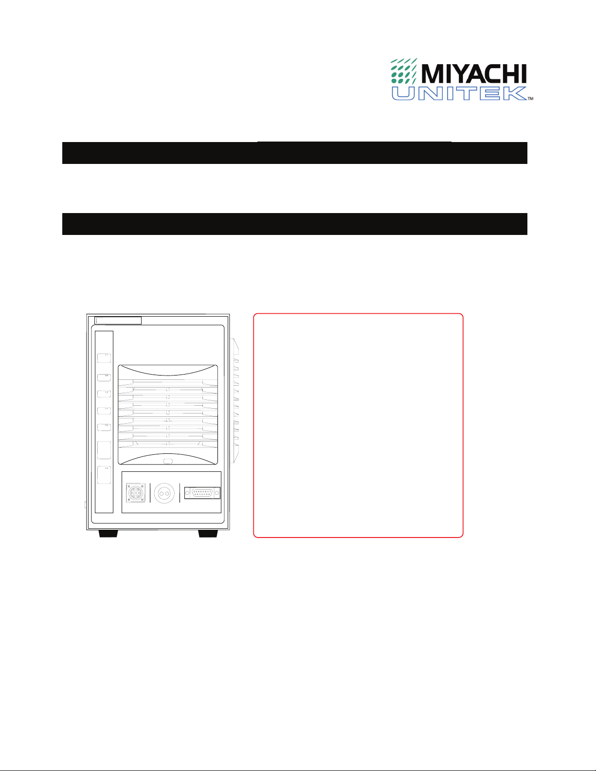
Miyachi Unitek UP-120B User manual

USER'SMANUAL 990-800
Revision A March 2003
Inverter Power Supply
UP-120B
Operation Manual
C
O
N
T
E
N
T
S
WEL
D
I
N
G
P
O
WER
S
U
PPLY
S
1
2
0
WEL
D
I
N
G
P
O
WER
S
U
PPLY1. For Correct Use 1-1to5
2. Introduction
2-1
3. Name and Functions of
Each Section
3-1to23
4. Connection Method 4- 1to2
5. Interface 5-1to6
6. Basic Operation
6-1
7. Time Chart
7-1
8. Maintenance 8-1to4
9. Specifications 9-1to10
10. Outline
10-1
11. Troubleshooting 11-1to3

Copyright © 2003 Unitek Miyachi Corporation
The engineering designs, drawings and data contained herein are
the proprietary work of UNITEK MIYACHI CORPORATION and may
not be reproduced, copied, exhibited or otherwise used without the
written authorization of UNITEK MIYACHI CORPORATION.
Printed in the United States of America.
REVISION RECORD
Revision EO Date Basis of Revision
A 19703 3/03 Original Release.

UP-120B
1-1
1. Special Precautions
Safety Precautions
Before using, read "Safety precautions"
carefully to understand the correct method
of use.
•These precautions are shown for safe
use of our products and for prevention of
damage or injury to operators or others.
Be sure to read each of them, since all of
them are important for safety.
•The meaning of the words and symbols is
as follows.
Do not touch the inside of the Power Supply unnecessarily.
Since very high voltages are applied to the inside of this Power Supply, it is
very dangerous to touch it unnecessarily. You may touch it only when you
replace the fuse or battery.
When inspecting the interior of the Power Supply, be sure to turn off the
power source of the Power Supply and wait for at least 5 minutes.
Never disassemble, repair or modify the Power Supply.
These actions can cause electric shock and fire. Do not do anything other
than the maintenance described in the operation manual.
Denotes operations and practices
that may imminently result in serious
injury or loss of life if not correctly
followed.
DANGER
!
Denotes operations and practices
that may result in serious injury or
loss of life if not correctly followed.
WARNING
!
Denotes operations and practices
that may result in personal injury or
damage to the equipment if not
correctly followed.
C
A
UTION
!
These symbols denote
"prohibition". They are
warnings about actions out
of the scope of the warranty
of the product.
These symbols denote
actions which operators
must take.
Each symbol with a triangle
denotes that the content
gives DANGER, WARNING
or CAUTION to the operator.
!
DANGER
!

UP-120B
1-2
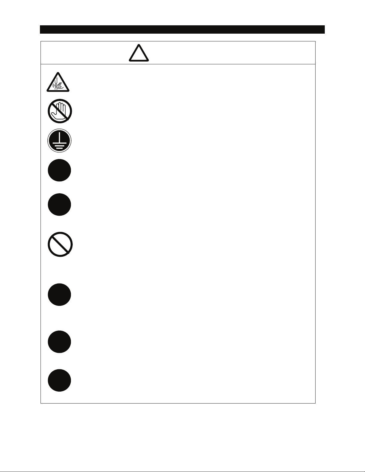
Do not put your hands between the electrodes.
When welding, keep your fingers and hands away from the electrodes.
Do not touch any welded part or electrodes during welding and just after
welding finished.
The welded part of a workpiece, electrodes and arm are very hot.
Do not touch them; otherwise you may be burnt.
Ground the equipment.
If the Power Supply is not grounded, you may get an electric shock when
there is trouble, or when electricity leaks.
Connect the specified cables securely.
Cables of insufficient current capacities and loose connections can cause fire
and electric shock.
Do not damage the power cable and connecting cables.
Do not tread on, twist or tense any cable. The power cable and connecting
cables may be broken, and that can cause electric shock and fire.
Stop the operation if any trouble occurs.
Continuous operation after occurrence of a trouble such as burning smell,
abnormal sound, abnormal heat, smoke, etc. can cause electric shock and
fire.
If such a trouble occurs, immediately consult Unitek Miyachi Corp. or your
distributor.
Persons with pacemakers must stay clear of the welding machine.
A person who uses a pacemaker must not approach the welding machine or
walk around the welding shop while the welding machine is in operation,
without being permitted by his/her doctor. The welding machine generates a
magnetic field and has effects on the operation of the pacemaker while it is
turned on.
Protective gear must be worn.
Put on protective gear such as protective gloves, long-sleeve jacket, leather
apron, etc. Surface flash and expulsion can burn the skin if they touch the
skin.
Wear protective glasses.
If you look at the flash directly during welding, your eyes may be damaged. If
any Surface flash and expulsion gets in your eye, you may lose your
eyesight.
W
A
RNING
!
!
!
!
!
!

UP-120B
1-3
Apply the specified source voltage.
Application of a voltage out of the specified range can cause fire and electric
shock.
Do not splash water on the equipment.
Water splashed over the electric parts, can cause electric shock and short
circuits.
Use proper tools (wire strippers, pressure wire connectors, etc.) for
termination of the connecting cables.
Do not cut the conductor of wire. A flaw on it can cause fire and electric
shock.
Install the equipment on firm and level surface.
If the equipment falls or drops, injury may result.
Do not sit on, do not put things on it.
Sitting on it, or putting things on it may cause malfunction.
Keep combustible matter away from the welding machine.
Surface flash and expulsion can ignite combustible matter. If it is impossible
to remove all combustible matter, cover them with non-combustible material.
Do not cover this equipment with a blanket, cloth, etc.
If such a cover is used, it may be heated and burn.
Do not use this Power Supply for purposes other than welding.
Use of this equipment in a manner other than specified can cause electric
shock and fire.
Use ear protectors.
Loud noises can damage hearing.
Keep a fire extinguisher nearby.
Keep a fire extinguisher in the welding shop in the case of fire.
Maintain and inspect the equipment periodically.
Maintain and inspect the equipment periodically, and repair any damage
nearby before starting operation.
CAUTION
!
!
!
!
!
!
!
!

UP-120B
1-4
Precautions for Handling
Install this Power Supply on a firm and level surface. If it is inclined, malfunction
may result.
For ventilation, provide 10
cm clearances to the intake and exhaust (page 8-3).
Do not install this Power Supply in the following places:
Damp places (where humidity is 90% or higher), dusty places, places where
chemicals are handled, places near a high-frequency noise source,
places where it is subjected to vibration and shock, hot or cold places (where
temperatures are above 40or below 5), and places where water will be
condensed.
Do not put a screw, a coin, etc., in the Power Supply, since they can cause a
malfunction.
Clean the outside of the Power Supply with a soft, dry cloth or one wet with a
little water. If it is very dirty, use diluted neutral detergent or alcohol. Do not use
paint thinner, benzine, etc., since they can discolor or deform the Power Supply.
Operate the Power Supply according to the method described in this operation
manual.
Operate the switches and buttons carefully by hand. If they are operated roughly
or with the tip of a screwdriver, a pen, etc. they may be broken.
Operate the switches and buttons one at a time. If two or more of them are
operated at a time, the Power Supply may have trouble or may be broken.

UP-120B
1-5
Warning Labels for Safety
Location: UP-120B interior, side surface of acrylic cover.
Output terminal cover.
Location: Power supply breaker cover.
DANGER
WHEN INSPECTING INTERNAL, MAKE SURE
TO TURN OFF MAIN CIRCUIT BREAKER
AND WAIT FOR AT LEAST 5 MINUTES
NOT TO GET AN ELECTRIC SHOCK.
HIGH
VOLTAGE
DANGER

UP-120B
1-2

UP-120A
2-1
2. Introduction
The Unitek Peco FINE SPOT-INVERTER UP-120B is an inverter-type power supply, large in
capacity and specially designed to be used for spot welding and fusing. In addition, it is small
in size and convenient to move or shift. Monitor function is provided, which enables judging
defective or non-defective welding.
Features
Has a welding current monitoring function for judgment of the weld quality.
Has six control systems (Primary constant-current effective value control,
secondary constant-current effective value control, secondary constant-power
effective value control, primary constant-current peak value control, secondary
constant-voltage effective value control and constant-phase control)for stable
weld quality.
Has an interrupting function([INTERRUPT]) to interrupt fusing current by
externally inputting a displacement of the electrode, etc., for stable fusing.
Since an inverter is used, the power factor is high and the power condition is
stabilized.
Various items can be set easily by the menu selection system.
Applicable to inverter transformers manufactured by various companies by
changing the frequency (600Hz/800Hz/1000Hz).
With four protective functions, the operator can work at his/her ease.
Overcurrent detecting function
No-current detecting function
Thermostat fault detecting function
Selfdiagnostics
Small and light, but having a capacity rating of 48kVA (at 440VAC input)and
maximum setting of 20kA.

UP-120A
2-2

UP-120B
3-1
3. Name and Functions of Each Section
UP-120B
Fig. 3-1
[WELD POWER]lamp (Green LED)
This lamp lights up when the power is supplied to UP-120B.
[READY]lamp (Green LED)
This lamp lights up when the system is ready to start welding.
To turn on this lamp:
[WELD ON/OFF]key
WELD ON/OFF setting of program unit UP-627A and
External WELD ON/OFF signal
must all be turned on.
[START]lamp (Green LED)
This lamp stays lit while the start signal is input.
PROGR
A
M
RESET
TROUBL E
MONI TOR
WEL D
TROUBL E
WEL D
I
/
ORS- 4 8 5
I NDI C
A
TOR
ST
A
RT
RE
A
DY
POWER
WEL D
W E L D I N G P O W E R S U P P L Y
IS-120B
COI L I N
TROUBLE
RESET
WELD
POWER
RE
A
DY
ST
A
RT
WELD
TROUBLE
WELD
ON/OFF
Frontpanel
FINE SPOT - INVERTER
PULL

UP-120B
3-2
[WELD]lamp (Green LED)
This lamp stays lit while the welding current is flowing.
[TROUBLE]lamp (Red LED)
This lamp lights up when trouble is detected. At this time, the program unit makes a
peeping sound, and the work done by UP-120B is interrupted.
[RESET]key
If this key is pressed while the [TROUBLE]lamp is lit, that lamp is turned off.
The [TROUBLE]lamp lights up again, however, as long as there is trouble.
Accordingly, remove the cause of the trouble before pressing this [RESET]key.
If the [TROUBLE]lamp lights up while work is being done, press the [RESET]key,
then input the start signal again, and the work continues.
[WELD ON/OFF]key
This key is one of those which are required for turning on the [READY]lamp.
Each time this key is pressed, it is turned ON and OFF alternately. If it is turned on,
[READY]lamp lights up, and if the key is turned off, the lamp goes off.
[RS-485]connector
For external communication.
Data Out "YES/NO" is selectable by setting DIP switch on the internal PC board
(Factory default is "YES"). This PC board is mounted rear left of the UP-120B. (See
Fig. 3-2)
When the DIP switch is turned on, weld time, current, count, etc., are output after
HOLD has ended through the RS-485 serial interface. (For transmission format, see
Serial Interface Specifications on p. 9-4.)
Duration of the Data Out is approx. 80
ms.
The next Start is disabled during the Data Out (See Time Chart).
When switching the DIP switch, be sure to turn
off the power supply and wait for at least 5
minutes to prevent electric shock.
DANGER
!

UP-120B
3-3
Fig. 3-2
[TOROIDAL COIL] connector
For a toroidal coil connection. Used for secondary constant-current effective value
control and secondary constant-power effective value control. (Toroidal coil is an
option.)
[PROGRAM UNIT] connector
Connects to Program Unit UP-627A or Monitor Unit UP-628A. Used for welding
schedule setting and/or reviewing monitor result.
Filter Cover
An air filter is provided inside this cover. To be removed for maintenance of the air
filter.
The fan motor may hurt your finger.
When replacing / cleaning it, be sure to turn off
the power supply.
DANGER
!
PC Boar d
Dataout:YESFront
Many DI P swi t ches ar e on t he PC boar d;
sel ect t he cor r ect one.
WhenchangingoverDIP
switch,takecarenot
todamagePCboard.
Dataout:NO
Setting DIP switch

UP-120B
3-4
Fig. 3-3
Connecting terminal block for external input/output signal
This terminal block is used to input the schedule signals and output trouble signals.
Welding Power Supply Breaker
For three-phase power supply.
Welding Power Supply Breaker Lever
Pulling up this Lever supplies power; pushing down, disconnect power supply.
Trip Button of Welding Power Supply Breaker
Checks trip operation of the Breaker. Periodic checks are recommended.
Welding Transformer [I/O]connector
For connecting [SENS]cable of welding transformer manufactured by Unitek
Miyachi Corp.
Terminal block for welding power output
This terminal block is used to connect to the input of the welding transformer.
Powersupplybreakercover
PEL3L 2L1
U V
POWER OUT
1
5
1
61
7
1
81
9
2
02
1
2
22
3
2
42
5
2
62
7
2
82
9
3
03
1
3
23
3
3
43
5
3
63
7
3
83
9
1
4
1
3
1
2
1
1
1
0
9
8
7
6
5
4
3
2
1
I/O terminal cover
Outputterminalcover
(withterminalcovermounted) (with terminal covers removed)
Rear panel
I/O

UP-120B
3-5
UP-627A (Sold separately)
Fig. 3-4
1[TROUBLE RESET]key
If this key is pressed while the [TROUBLE]lamp of UP-120B is lit, the lamp goes off.
It has the same function as the [RESET]key of UP-120B.
2[CURSOR]keys
These keys are used to move the cursor ( or )to select an item.
3[+ON/-OFF]keys
These keys are used to change the value of a selected item or turn it on and off.
When the [+ON]key is pressed, the selected value increases, and if the [-OFF]
key is pressed, the value decreases. The selected item is turned on by pressing the
[+ON]key, and turned off by pressing the [-OFF]key. To switch the range for
[CURR RANGE](See p. 3-19), press [+ON]for [LOW]; [-OFF]for [HIGH].
4[ENTER]key
This key is used to write the set or changed value and [ON/OFF]data in UP-627A.
After any data is set or changed, be sure to press this [ENTER]key to write that
data before moving the cursor.
If this [ENTER]key is not pressed, UP-627A does not recognize the set data.
5[MENU]key
This key is used to display the [MENU]screen. Press this key to return to [MENU]
screen from any other screens.
6Connector
This connector is used to connect the circuit cable. Connect the other end of the
cable to the [PROGRAM UNIT]connector of UP-120B.
W
ELDINGSCHEDUL E P R O G R A M U N I T
ON
OFF
CURSOR
MA-627ATROUBLE
RESET ENTER
MENU
1 2 3 4 5
6

UP-120B
3-6
Explanation of Screen
Hatched letters (000)An item for which a value must be input or
ON/OFF is set.
Move the cursor ( ) to the number or
ON (or OFF)to be set or changed, and
press [+ON/-OFF]key.
Outline letters () An item which is indicated on the screen
but cannot be changed by any operation.
[MENU]screen
UP-627A has various functions, which are set in the respective screens. [MENU]
screen displays those functions in a menu form.
Move the cursor () to an item you desire; press [ENTER] key to go to the selected
screen except MODE SWITCH screen.
Note: To go to MODE SWITCH screen , press [MENU]key and [TROUBLE
RESET]key on the program unit panel simultaneously for 4 seconds.
POWER SUPPLY STATE screen
This screen is used to display and set the information on UP-120B.
Letters used in the following explanation
[MENU]
POWER SUPPLY STATE COPY SETUP
DATA
SCHEDULE SCHEDULE MODE
MONITOR MODE SWITCH
MONITOR SET STEPPER COUNT
HEAT INCREASE
INITIALIZE
-POWER SUPPLY STATE
CONTROL #0001
PROGRAMED DATE 2000. 12. 03
POWER SOURCE FREQUENCY
WELD POWER FREQUENCY
MA-627A ROM VERSION #[]
IS-120B ROM VERSION #[]
This screen shows initial settings.
(a)
(b)
(c)
(d)
(e)
(f)
1
2
3
4
5
6
7
8
9
10
11

UP-120B
3-7
(a)CONTROL #
Input the identification No. of your UP-120B.
If you have two or more units of UP-120B, input 0001 for the first one, 0002 for the
second one, 0003 for the third one, and so on.
(b)PROGRAMED DATE
Input the date when the data is set.
(c)POWER SOURCE FREQUENCY
The frequency of the welding power is measured and indicated automatically.
(d)WELD POWER FREQUENCY
Change the output frequency of the inverter power supply of UP-120B with dip
switches in the body. The frequency set with the dip switches is indicated as the
WELD POWER FREQUENCY. (It is set to 1000Hz when delivered.)
Fig. 3-5
(e)UP-627A ROM VERSION #
The ROM version No. of program unit UP-627A is indicated.
(f)UP-120B ROM VERSION #
The ROM version No. of UP-120B is indicated.
DIP switch setting
Printed circuit board
Setting to 1000Hz
Settingto800HzSetting to 600Hz
IS- 120B
rear
Make sure the DIP switches
are set correctly. When changing
over DIP switch,
take care not to
damage circuit
board.

UP-120B
3-8
SCHEDULE screen
Up to 15 welding schedules can be set on UP-120B. Those schedules are indicated
as SCHEDULE #01 to #15.
This screen is used to set the schedule No., length of weld time, welding current, and
so on. This data can be indicated in the 12 modes as shown below, but the indicated
items are the same in all the modes.
HEAT has two setting modes, HIGH and LOW ranges (See CURR RANGE on page
3-19). The following screens are for HIGH range mode. The indication mode, ms
mode or CYC mode, can be changed with CYC WELD (See page 3-18)on the
MODE SWITCH screen.
Primary constant-current
effective value control ms mode
Primary constant-current
effective value control CYC mode
-SCHEDULE #01 CTRL 0
PRIMARY RMS
SQD SQZ WE1 COOL WE2 HOLD OFF
TIME 0000 0000 000 000 000 000 0000
ms
UP SLOPE 000 ms
DOWN SLOPE 000 ms
HEAT 00.1 00.1 kA
PULSATION 1GAIN(1-9) 1
VALVE #1WELD ON/OFF OFF
-SCHEDULE #01CTRL 0
PRIMARY RMS
SQD SQZ WE1 COOL WE2 HOLD OFF
TIME 000 000 00 00 00 00 00 CYC
UP SLOPE 00 CYC
DOWN SLOPE 00 CYC
HEAT 00.1 00.1 kA
PULSATION 1GAIN(1-9) 1
VALVE #1WELD ON/OFF OFF
Secondary constant-current
effective value control ms mode
Secondary constant-current
effective value control CYC mode
-SCHEDULE #01 CTRL 1
SECONDARY RMS
SQD SQZ WE1 COOL WE2 HOLD OFF
TIME 0000 0000 000 000 000 000 0000
ms
UP SLOPE 000 ms
DOWN SLOPE 000 ms
HEAT 00.1 00.1 kA
PULSATION 1GAIN(1-9) 1
VALVE #1WELD ON/OFF OFF
-SCHEDULE #01 CTRL 1
SECONDARY RMS
SQD SQZ WE1 COOL WE2 HOLD OFF
TIME 000 000 00 00 00 00 00 CYC
UP SLOPE 00 CYC
DOWN SLOPE 00 CYC
HEAT 00.1 00.1 kA
PULSATION 1GAIN(1-9) 1
VALVE #1WELD ON/OFF OFF
Secondary constant-power
effective value control ms mode
Secondary constant-power
effective value control CYC mode

UP-120B
3-9
-SCHEDULE #01 CTRL 2
POWER RMS
SQD SQZ WE1 COOL WE2 HOLD OFF
TIME 0000 0000 000 000 000 000 0000
ms
UP SLOPE 000 ms
DOWN SLOPE 000 ms
HEAT 00.1 00.1 kW
PULSATION 1GAIN(1-9) 1
VALVE #1WELD ON/OFF OFF
-SCHEDULE #01 CTRL 2
POWER RMS
SQD SQZ WE1 COOL WE2 HOLD OFF
TIME 000 000 00 00 00 00 00 CYC
UP SLOPE 00 CYC
DOWN SLOPE 00 CYC
HEAT 00.1 00.1 kW
PULSATION 1GAIN(1-9) 1
VALVE #1WELD ON/OFF OFF
Primary constant-current
peak value control ms mode
Primary constant-current
peak value control CYC mode
-SCHEDULE #01 CTRL 3
PRIMARY LIMI
T
SQD SQZ WE1 COOL WE2 HOLD OFF
TIME 0000 0000 000 000 000 000 0000
ms
UP SLOPE 000 ms
DOWN SLOPE 000 ms
HEAT 00.1 00.1 kA
PULSATION 1GAIN(1-9) 1
VALVE #1WELD ON/OFF OFF
-SCHEDULE #01 CTRL 3
PRIMARY LIMI
T
SQD SQZ WE1 COOL WE2 HOLD OFF
TIME 000 000 00 00 00 00 00 CYC
UP SLOPE 00 CYC
DOWN SLOPE 00 CYC
HEAT 00.1 00.1 kA
PULSATION 1GAIN(1-9) 1
VALVE #1WELD ON/OFF OFF
Secondary constant-voltage
effective value control ms mode
Secondary constant-voltage
effective value control CYC mode
-SCHEDULE #01 CTRL 4
VOLTAGE RMS
SQD SQZ WE1 COOL WE2 HOLD OFF
TIME 0000 0000 000 000 000 000 0000
ms
UP SLOPE 000 ms
DOWN SLOPE 000 ms
HEAT 10.0 10.0 V
PULSATION 1GAIN(1-9) 1
VALVE #1WELD ON/OFF OFF
-SCHEDULE #01 CTRL 4
VOLTAGE RMS
SQD SQZ WE1 COOL WE2 HOLD OFF
TIME 000 000 00 00 00 00 00 CYC
UP SLOPE 00 CYC
DOWN SLOPE 00 CYC
HEAT 10.0 10.0 V
PULSATION 1GAIN(1-9) 1
VALVE #1WELD ON/OFF OFF
Constant-phase control ms mode Constant-phase control CYC mode

UP-120B
3-10
When using another maker's transformer and <SECONDARY RMS>, <POWER
RMS>or <FIXED PULSE>, connect the toroidal coil (sold separately)to the
secondary of the transformer. If it is not connected, the no connection of the
toroidal coil will be judged as non-current and error message E-05 is displayed.
Even when E-05 (non-current error)is displayed, current flows; take care
in handling.
-SCHEDULE #01 CTRL 5
FIXED PULSE
SQD SQZ WE1 COOL WE2 HOLD OFF
TIME 0000 0000 000 000 000 000 0000 m
s
UP SLOPE 000 ms
DOWN SLOPE 000 ms
HEAT 10.0 10.0 %
PULSATION 1GAIN(1-9) 1
VALVE #1WELD ON/OFF OFF
-SCHEDULE #01 CTRL 5
FIXED PULSE
SQD SQZ WE1 COOL WE2 HOLD OFF
TIME 000 000 00 00 00 00 00 CYC
UP SLOPE 00 CYC
DOWN SLOPE 00 CYC
HEAT 10.0 10.0 %
PULSATION 1GAIN(1-9) 1
VALVE #1WELD ON/OFF OFF
Each screen shows initial settings in HIGH range mode. In LOW range mode, HEAT settings
are 0.10 kA and 0.10 kW, respectively. HIGH and LOW ranges do not affect Secondary
constant-voltage effective value control and Constant-phase control.
(a)SCHEDULE #
Select one of #1 to #15 for the SCHEDULE to be set.
Under ordinary circumstances, select #1 first, then select the other in order.
(b)CTRL
Select one from the following six welding current control methods.
0 <PRIMARY RMS>
Primary constant-current effective value control
1 <SECONDARY RMS> Secondary constant-current effective value control
2 <POWER RMS> Secondary constant-power effective value control
3 <PRIMARY LIMIT> Primary constant-current peak value control
4 <VOLTAGE RMS> Secondary constant-voltage effective value control
5 <FIXED PULSE> Constant-phase control
(c)TIME
Set the time for each operation during the welding. The unit of the time is ms or CYC.
For each operation, see the time chart.
SQD / Squeeze delay time
Length of time added to SQZ only for the
first weld after start signal in repeat operation
SQZ / Squeeze time
Length of time until proper squeeze is
applied to workpiece
WE1 / Weld 1 time
Length of time to supply welding current
CAUTION
D
A
NGER
!
Table of contents
Other Miyachi Unitek Power Supply manuals