Mizar Tilt User manual

2
www.mizarimaging.com
Tilt User’s Guide
© 2019 Mizar Imaging, LLC. All Rights Reserved.
7 MBL Street / Lillie 220 / Woods Hole, MA 02543 / +1.508.939.7500
Table of Contents
Warnings and Safety 3
Definitions of Safety Symbols 3
Warnings 4
Safety Features 5
How the Tilt Works 6
Getting to Know Your Tilt 7
Getting to Know Your Tilt 8
Adjustment Tips 9
How to Image 10
Advanced Alignment and Installation 12
Installation 12
Aligning Tilt Optical Components 13
Tips for Mounting Samples 17
Recommended Specimen Chambers 18
Assembling Mizar Cube Chambers 19
Troubleshooting 21

3
www.mizarimaging.com
Tilt User’s Guide
Warnings and Safety
This product is designed to be completely safe when used as intended. Any other use of
the Tilt not outlined in this manual — including modifications and/or disabling safety fea-
tures — may result in serious injury or property damage. In order to ensure safe operation,
take care to review the following safety information before using the Tilt.
Definitions of Safety Symbols
SYMBOLS USED IN THIS MANUAL
Warning Notice
Instructions containing a warning notice detail the hazards and
safe operation of the Tilt. Ignoring these safety instructions can
result in serious injury or property damage.
SYMBOLS USED ON THE TILT
Laser Hazard Label
This symbol is displayed near the laser output on the Tilt to warn
the user that this product emits laser light. Exposing your eyes or
skin to the emitted laser light may result in injury.

4
www.mizarimaging.com
Tilt User’s Guide
Warnings
The Tilt uses lasers as a light source.
1 – Laser Safety
A focused sheet of laser light is emitted from the front lens of the Tilt. Never look directly
into emitted or reflected laser light — doing so may cause permanent vision loss. Keep the
light path clear of mirrors or other reflective objects that may redirect the laser light.
The Tilt uses Class 3B/IIIb lasers. Consult with your institute’s laser safety officer for
institute safety procedures. Be sure to read and follow all safety instructions from the
laser manufacturer.
2 – Intended Use
This product is intended only to provide tilted excitation for fluorescent samples during mi-
croscopic imaging. During operation, this product must be attached to an approved inverted
microscope stand. Use of the Tilt for any other purpose, including the use of unsupported
microscope stands and laser products, can result in serious injury and property damage.
Complete information on microscope stand compatibility and supported laser products can
be obtained from Mizar Imaging.
3 – Installation
Installation of the Tilt must only be performed by a trained service professional. Improper
setup may impair performance of the Tilt and can result in unsafe exposure laser light.
4 – Removal, Modification, and Repair
Do not attempt to remove or disassemble any part of the Tilt. Any modifications or at-
tempts to repair this product can result in unsafe exposure to laser light. Please contact
Mizar Imaging if the Tilt requires service.
5 – Precautions at Startup
Before operating the Tilt or turning on the laser source, ensure that the optical fiber carry-
ing the laser light is securely fixed to both the Tilt and the laser launch. Check that all safety
features included with the Tilt are in place.

5
www.mizarimaging.com
Tilt User’s Guide
Safety Features
In order to reduce the risk of injury due to laser exposure, the Tilt is equipped several safety
features. These include, a laser shield (I), a light trap (II), locking screws (III), and a fiber
adapter cover (IV). Removal of any of these components will increase the risk of injury.
I. Laser Shield – The laser shield sits above the sample and is intended to protect the
user from stray or reflected laser light
II. Light Trap – The light trap is placed opposite of the optical assembly aperture and pre-
vents further travel of any laser light that has passed through the sample field.
III. Locking Screws – The locking screws are located on each of the Tilt sled arms and
prevent removal of the sled/optical assembly from the stage.
I V. Fiber Adapter Cover – The fiber adapter cover is intended to prevent removal of the
optical fiber during operation and to protect the fiber from accidental damage.

6
www.mizarimaging.com
Tilt User’s Guide
How the Tilt Works
The Tilt from Mizar Imaging takes advantage of Lateral Interference Tilted Excitation
(LITE) microscopy as described in Fadero, et al., 2018. LITE is a novel variation of light
sheet fluorescence (LSFM), or single plane illumination microscopy (SPIM).
The design of most LSFM/SPIM microscopes involve the use of two objectives, the
orientation of which limits the numerical aperture (NA) of the detection objective. The Tilt
from Mizar Imaging gives researchers the freedom to use LSFM/SPIM with high resolution,
high-NA objectives.
LITE uses a cylindrical lens to turn a collimated beam of light into a wedge-shaped beam
that converges to a sheet at the lens’s focal point. However, with a cylindrical lens alone
the length of this sheet would be too narrow to cover the field of view of the objective,
resulting in poor illumination of the sample.
To solve this problem, we use a photomask containing four slits before the beam enters
the cylindrical lens. This method (Golub, et al., 2015) has the effect of creating an interfer-
ence pattern at the focal point of the cylindrical lens. This, mathematically and in practice,
elongates the sheet to ~300 μM, with a thickness about 4 μM.
In order to image samples within the working distance of high-NA objectives, the excitation
beam is angled (“tilted”) such that the bottom ray of the converging sheet is parallel to
the focal plane of the detection objective. This way, the light sheet forms at the focal plane
of the detection objective. This ability to have the thinnest part of the light sheet directly
at the focal plane of any objective — including high NA and oil immersion objectives — is
what gives the LITE technology its edge.
Laser
Detection Objective
Photomask
Cylindrical Lens
Light Trap

7
www.mizarimaging.com
Tilt User’s Guide
Getting to Know Your Tilt
In order to begin imaging, you will need to position center of the light sheet at the focal
point of the objective. To accomplish this, you will make use of the three colored position-
ing knobs on the Tilt (Fig A).
1 – FRONT HEIGHT ADJUSTMENT (GREEN)
The Green knob adjusts the height of the front side of the Tilt (Fig B), effectively sweeping
the sheet up and down above the objective. Adjust the Green knob to position the light
sheet vertically at the focal point of your objective.
2 – LATERAL ADJUSTMENT (BLUE)
Adjusting the Blue knob will slide the Tilt sled forward and back (Fig B), thereby changing
the lateral position of the light sheet. Use the Blue knob to center the focused light sheet
over your objective.
3 – REAR HEIGHT ADJUSTMENT (PINK)
Turning the Pink knob will raise and lower the height of the back side of the Tilt
(Fig. B). Make use of this knob to adjust the final Tilt angle after positioning the light
sheet over the objective using the Blue and Green knobs.

9
www.mizarimaging.com
Tilt User’s Guide
Adjustment Tips
Below is a quick method to learn how adjustments are made to the Tilt lightsheet:
1. Turn the laser on low power, roughly 2-5 mW.
2. Place a colored acrylic slide onto the sample holder platform (as pictured).
3. Adjust the (Green) Front Height Adjustment knob located below the Tilt stage (Fig A-1).
You will see one to four lightsheets move across the slide.
4. Turn the (Blue) Lateral Adjustment knob (Fig A-2) to see its effect on the lightsheet.
This knob moves the optic assembly closer or further from the sample holder platform
(Fig B-2). You will see the lightsheets either converge closer to the optic assembly or
further away depending on which way you are turning the knob.
5. While continuing to turn the Blue Focusing knob, place your other hand on the Green
Angle Adjustment knob and begin to fine tune the lightsheet. Try to get the narrowest
lightsheet you can directly above the objective lens.
6. Once you have developed a sense for how the adjustments of both the (Blue) and
(Green) work, focus your lightsheet ~3 mm to the right of the point directly above the
objective lens. Once you have your sample on the microscope, differences in refractive
index between air and your sample will cause the lightsheet to shift about 1-4 mm.
7. Zero the included inclinometer to the stage and then place it on one of the Tilt sled
arms. Turn the (Pink) Rear Height Adjustment knob (Fig A-3) until the inclinometer
reads the desired Tilt angle (~3.3-3.4°).

10
www.mizarimaging.com
Tilt User’s Guide
How to Image
1. Check the LIGHTSHEET
Your Tilt was properly aligned when installed and should not need to be realigned if undis-
turbed. However, it is good practice to verify that everything looks good prior to imaging,
and only takes a few seconds:
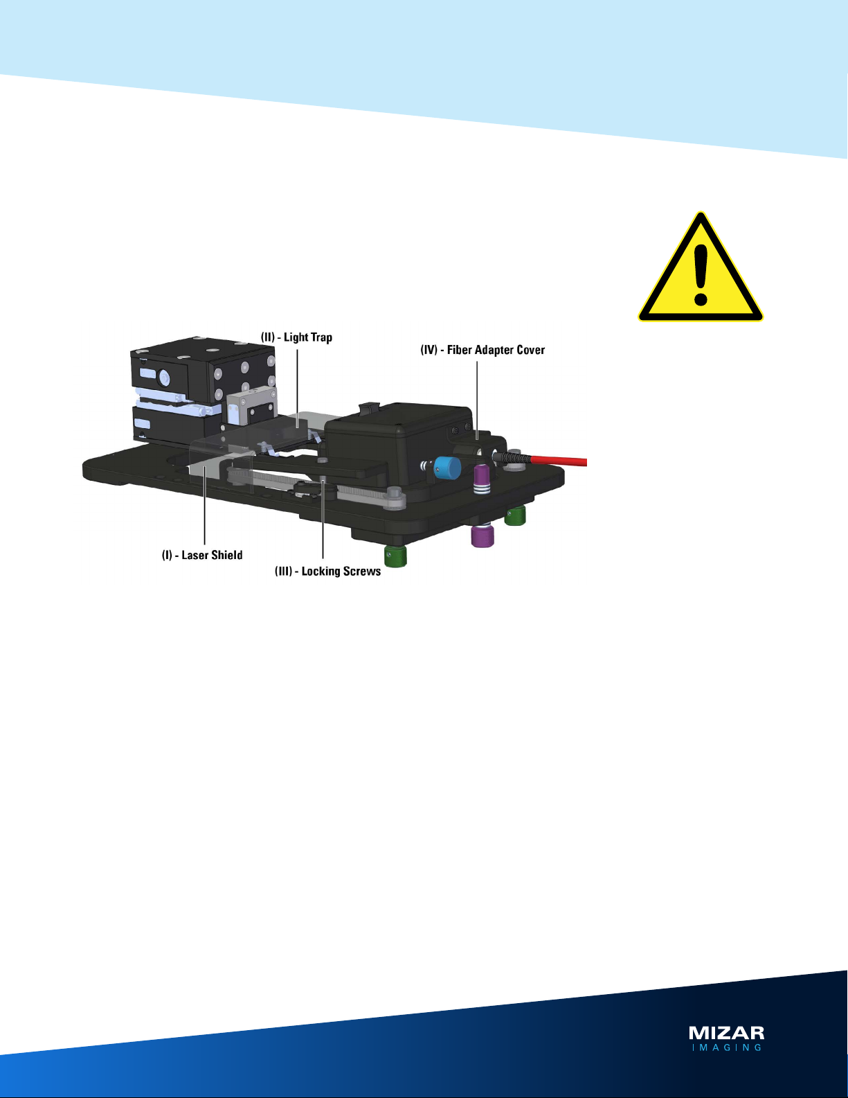
• With the laser on low power (~2 mW) take a piece of lens paper (or a lint-free wipe) and
hold it over the front lens cover where the four light sheets emerge from the Tilt optic
assembly.
• Check to see that the light sheet is evenly illuminated side-to-side, i.e., that one side is
not brighter than the other.
• Check also that the top pair is equal in brightness to the bottom pair.
Sheet not looking good? See Aligning Tilt Optical Components on pages 12-16.
Or call us for support at +1.508.939.7500.
2. Load your sample
Mount your specimens in a suitable sample chamber, and place sample chamber onto the
sample holder platform.
For detailed tips on mounting samples seeTips for Mounting Samples on page 17.
See also Recommended Specimen Chambers on page 18.
3. Coarse / Fine Focus the Lightsheet
3.1 Locate specimen and focal plane of interest.
With the laser off, use any type of transmitted light to find your sample. Focus on the ap-
proximate focal plane of interest.
3.2 Switch to live view on your computer.
Having located your sample and the focal plane of interest, turn off transmitted light and
direct 100% of the light path of your microscope to the camera. Switch to live mode in your
microscope’s software.
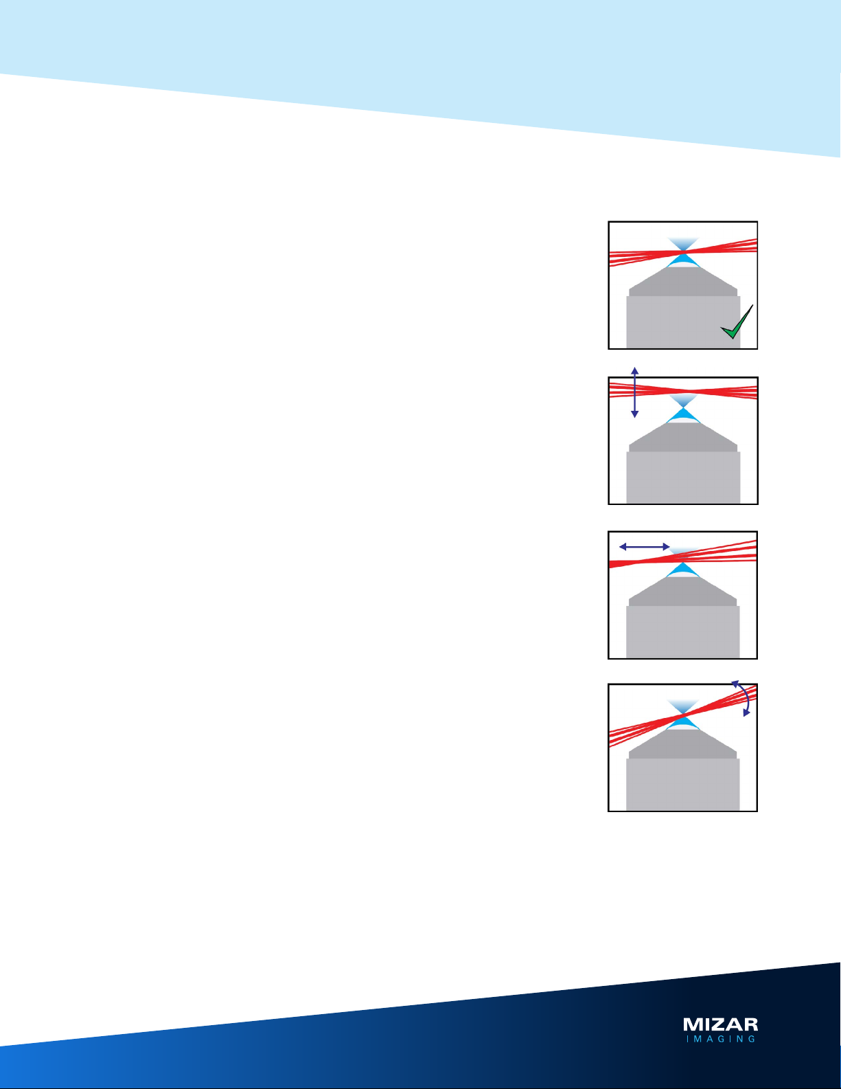
3.3 Coarse adjustment of the lightsheet.
• Set laser power to medium-low (10-30 mW) and open the shutter to the laser.
• Turn the (Green) Angle Adjustment knob on the bottom of the Tilt stage until you see
fluorescent signal from your sample. You may need to adjust your camera exposure or
perform a quick autoscale.
• With autoscaling off, adjust the (Green) knob until the image is as its brightest.

11
www.mizarimaging.com
Tilt User’s Guide
3.4 Fine adjustment (focusing) of the lightsheet.
For experience and visualization of how fine adjustment works, we recommend
doing the training exercise described in AdjustmentTips on page 8.
• With autoscaling off, turn the (Green) adjustment knob back and forth to sweep the
sheet/s through the sample.
• If your sheet is positioned correctly, you will see a single bright image on the screen as
you move the sheet through the sample. If so, you are done.
• If the sheet is not centered over the objective, your sample will be illuminated multiple
times as the four component-sheets are passing through your sample.
• Use the (Green) knob to set the lightsheet to the centermost “dim” spot.
• Turn the (Blue) knob to move the Tilt assembly either forward or back — in the direction
that makes the image on screen brighter.
• Repeat the above steps until only a single bright image is seen when adjusting the
(Green) knob.
3.5 Check the angle of the lightsheet.
• Use the digital inclinometer included with the Tilt to check angle of the your lightsheet.
Be sure to zero the inclinometer on the stage prior to measuring.
• If your lightsheet is outside normal operating range (~3.3° +/- 0.5°) use the (Pink) Rear
Height Adjustment knob to raise or lower the back part of the Tilt.
• Re-adjust the (Green) knob so that your sample is illuminated.
4. Ready to Image
4.1 Adjust laser power and camera settings.
Once you have completed adjustments to the lightsheet, you are ready to modify laser
power and camera settings to make sure you have optimal illumination and acquisition
settings ahead of capturing images. As a general rule, always start with the laser power
being as low as possible and only turn up as needed.
4.2 Fine tune lightsheet when changing field of view
During your imaging session, you may move to a different specimen within the sample
chamber. It is the best practice to fine tune the vertical position of the sheet for each new
field of view, in case the focus has changed slightly. Again, with autoscaling off, adjust the
(Green) adjustment knob until the brightest image is on the screen. If needed, this should
just be a very slight shift in the sheet height. The higher the NA of the objective, the more
important this will be.

12
www.mizarimaging.com
Tilt User’s Guide
Advanced Alignment
and Installation
1. Installation
Your Tilt will be installed at delivery. These steps must only be performed by a trained
service professional.
1.1 Remove existing microscope stage
The Tilt replaces your existing microscope stage. To remove your existing stage, remove
the screws securing it to the stand and lift the stage up.
1.2 Install stage adapters (if needed)
Use the provided screws to attach the provided stage adapters. Note that certain stands
require only spacers for mounting the Tilt.
1.3 Affix theTilt stage
Place the Tilt stage atop your stand and affix it to the stage adapters or through the spacers
using the screws from your existing microscope stage.
1.4 Install the Tilt optical assembly
Place the Tilt optical assembly on top of the three adjustable posts (above the Green and
Pink knobs) on your Tilt stage. Attach a single mode fiber from your laser launch to the rear
of the Tilt optical assembly. To prevent removal of the optical assembly from the stage,
install the provided screws through the holes in each the top and bottom arms.
1.5 Install the safety features
Attach the Fiber Cover, Light Trap, and Laser Shield with the provided hardware.
1.5 Install the stage in your software
The Tilt uses an ASI MS-2000 stage controller. Most common imaging software packages
contain the appropriate ASI drivers — if not, check with your software provider for compati-
bility. When adding the device to your software, set the baud rate to 115200, and verify that
dip switches 4 and 5 on the rear of the controller are both set to the “down” position.

13
www.mizarimaging.com
Tilt User’s Guide
Advanced Alignment
and Installation
2. Aligning Tilt Optical Components
WARNING: Aligning optical components should only be carried out by installer or certi-
fied engineer. Your Tilt will be properly aligned upon its initial installation, and only on rare
instances will it become necessary to perform a realignment. If you feel yourTilt optical
components require realigning call our trained scientists at +1.508.939.7500.
TO BE CARRIED OUT ONLY BY INSTALLER OR CERTIFIED ENGINEER:
Inside the Tilt enclosure, there are two mirrors used for aligning the collimated laser with
the lens assembly. Each has two screws for adjustment — one for horizontal aiming, the
other for vertical.

14
www.mizarimaging.com
Tilt User’s Guide
Advanced Alignment
and Installation
Before starting, print the mirror and collimator alignment targets, making sure
not to “scale” the page when printing. Cut and fold the targets where indicated.
To collimate the beam:
1. Couple a low powered alignment laser (“Visual Fault Locator” or similar) to the back of
the Tilt. Make sure the fiber and fiber coupler are matched (angled or straight). Alterna-
tively, use a laser launch set to <2mW.
2. Remove the collimating lens by loosening the three set screws and pulling
straight back.
3. Set the lens on a flat surface and ensure it is pointed away from nearby people.
4. Turn on the laser and aim it at the alignment template. Adjust the beam by turning the
threaded head of the collimating lens until the beam fills the target.
5. Move the template along the beam path at various distance (short to long). Ensure
that the beam neither converges nor diverges and that it fills the template circle at all
distances. If the beam shrinks/expands at any point along this length, readjust the lens.

15
www.mizarimaging.com
Tilt User’s Guide
Advanced Alignment
and Installation
To align the mirrors:
1. Open the top lid of the Tilt and hang the alignment target over the front edge,
blocking the path to the lens. Make sure the bottom of the target is flush with
the bottom surface of the Tilt enclosure and center the target in the window.
2. Connect a fiber-coupled low power alignment laser (“Visual Fault Locator”) to
the Tilt, making sure the fiber coupler on the collimating lens is properly matched
with the fiber.
3. Turn on the laser. You should see an ellipse projected onto the alignment target.
4. Using the adjustment knobs on each of the mirrors, center the ellipse both vertically
and horizontally within the target — making sure to “fill” the target ellipse as much as
possible, and that the ellipse is brightest in the center. Refer to the tips and figure on
the next page for details on the function of each alignment screw.
5. After the beam is centered, remove the alignment target.
6. You should see a pattern of 4 lines, with the center 2 lines thicker than the top and
bottom. Verify that the pattern is symmetric both vertically and from left to right.

Tilt User’s Guide
16
www.mizarimaging.com
Advanced Alignment
and Installation
Mirror Alignment Tips:
• The best way to get a sense of how the alignment works is to adjust the
knobs and monitor how the adjustment affects the position and shape of
your beam - both at the target before the lens and the sheets after the lens.
Screws 1 and 4 move the beam vertically, screws 2 and 3 adjust horizontal
position.
• Generally speaking, Mirror 2 will be used to set the final vertical and lateral
positions, and Mirror 1 is used to “fill” Mirror 2. Issues with ellipse width/
height (too narrow/short), rotation, twisting, or clipping result from poor
alignment of Mirror 1. Adjust knobs 1 and 2 until the ellipse almost fills the
template — centering the ellipse on the target with knobs 3 and 4 on Mirror 2
as you go.
• If the beam is not entering the lens straight, the focal distance left-to-right will
be slightly different, resulting in a pattern similar to the “mirrors not square”
example above. Adjust the lateral aiming of the beam to correct for this.

17
www.mizarimaging.com
Tilt User’s Guide
Tips for Mounting Samples
Sample prep with the Tilt is straightforward, and indeed is similar to how you would nor-
mally mount a sample for imaging on any inverted microscope. That said, there are a few
key considerations to keep in mind when mounting samples for the Tilt.
2.1 Mount as you normally would
As a first pass, mount your samples as you would normally mount them for imaging on an
inverted microscope. For instance, if you immobilize your sample in 0.5% agarose, then do
that as well for imaging with the Tilt; if you do some sort of trick to bring your sample as
close to the cover slip as possible, such as glue, then use that as well with the Tilt; etc.
2.2 Tilt-specific considerations
The goal here is to maintain an unobstructed lightsheet all the way to your sample of
interest. Anything that gets in the way of your lightsheet (meniscus of the medium, a dirty
side wall of the sample chamber, other specimens, etc.) can create shadows and/or act as
a lens (“Anything curved can act as a lens”) and lead to a deterioration of the lightsheet.
Here are several tips for minimizing obstructions:
• Keep the sides of your sample chamber clear of fingerprints, oil, grease, etc.!
• Make sure there is adequate medium in your sample chamber. The meniscus can have a
lensing effect and distort the incoming lightsheet.
• If you use agarose or similar mounting gel, make sure you fill the entire well - either with
the gel or a medium that matches its refractive index (i.e. water for agarose). Also make
sure the gelling agent is well dissolved/incorporated. Undissolved particulate can cause
shadowing. Boiling for a longer period of time or filtering will help with this.
• If your specimen has features that obstruct the path of the lightsheet — such as a large
yolk sac — orient the sample with your region of interest facing the incoming lightsheet,
such that the obstructing element is not in the way.
• Mount your samples at low density. If plating cells, plate at low density as the “shad-
ows” from a nearby cell may in some cases disrupt the lightsheet. The same principle
holds for larger specimens.
• Sample multiple specimens per well, and multiple wells. Illumination artifacts sometimes
vary between individual specimens within a single well. Mount a sufficient number of
specimens to allow adequate sampling.

18
www.mizarimaging.com
Tilt User’s Guide
Recommended
Specimen Chambers
The key to successful imaging with the Tilt is an imaging chamber with flat, optically clear
sides to allow an unobstructed path for the lightsheet. Currently there are two commercial
options we routinely use.
Mizar Cubes on #1.5 coverslips.
The Mizar Cube chambers are open-ended modified cuvettes placed on coverslips. They are
custom-made from the same high-quality borosilicate glass as cuvettes and are reusable
and autoclavable. In contrast to manufactured chambers, quality of the side walls is consis-
tent and easy to control for. As long as they are kept clean and free of fingerprints, grease
(used for mounting; see below), etc., the cuvette glass is ideal for lightsheet imaging.
ibidi μ-Slide 2/4/8 Well chambers
The ibidi μ-Slide 2, 4, and 8-well chambered coverslips come pre-sterilized, and are a good
disposable option for general use and cultured cells. Many scientists already comfortable
with culturing cells on chambered slides prefer this option, as only minimal changes in
workflow and sample prep are required for successful lightsheet imaging.
For information on ibidi μ-Slides, visit: https://ibidi.com/13-chambered-coverslips
Other products in the ibidi μ-Slide line that contain round chambers are NOT suitable for
use with the Tilt.
Note: Manufacturing of imaging dishes typically does not include quality control for the
side walls. We occasionally find a chamber whose side walls distort the lightsheet. In these
cases, we recommend either scanning for areas less impacted by the imperfections or
mounting the sample in a different chamber altogether.

19
www.mizarimaging.com
Tilt User’s Guide
Assembling Mizar
Cube Chambers
Everything you will need to get started:
Mizar Cubes, Mizar Cube holder w/ helper insert, 22x40mm #1.5 coverslips,
silicon vacuum grease
How to assemble Mizar Cube imaging chambers
1. Spread a thin layer of vacuum grease on the inside of a petri dish, or similar flat surface.
2. Using a gloved hand to avoid fingerprints, firmly press a Mizar Cube into the thin
layer of grease; inspect the bottom of the Mizar Cube for complete coverage with
the grease.

20
www.mizarimaging.com
Tilt User’s Guide
Assembling Mizar
Cube Chambers
3. Place the helper insert inside the Mizar Cube holder, and lay a 22x40mm
coverslip on top
4. Align the Mizar Cube squarely with the coverslip and press firmly to seal the
Mizar Cube.
5. The assembled Mizar Cube chamber is now ready to loaded with your sample. Alterna-
tively, a sample can be immobilized on a 22x40mm coverslip prior to sealing the Mizar
Cube chamber around it and filling with media.
Table of contents