4
Manual
Manual Expert 1400/3400 GB 0704
MJK Automation A/S
Byageren 7
DK-2850 Naerum
Denmark
Tel.: +45 45 56 06 56
Fax: +45 45 56 06 46
www.mjk.com
Introduction
Thank you for choosing ExpertTM Level Transmitter.
We have done everything possible to make a level
transmitter that can fulfil all your demands.
ExpertTM Level Transmitter is suitable for all kinds of level
measurements. It can control and supervise levels in wells
and tanks - including aggressive and polluted media.
The ExpertTM Level Transmitter is both easy to install and
put into service, but read this manual first - then you will
get the most benefits from the ExpertTM Level Transmitter
right from the beginning.
You can always contact your representative or the MJK
Service Hotline for advice and guidance. Also, take a
look at http://www.mjk.com
ExpertTM Level Transmitter is registered trademark of MJK.
Thank you for choosing MJK Automation A/S as your
supplier of hydrostatic level transmitter.
Product identification
It is very important for the overall measuring accuracy that
the pressure transmitter has the correct pressure range.
Check that the item(s) delivered corresponds to the
ordered item(s) by means of the information on the label
on the packing:
On the model 3400 transmitters, the pressure ranges to-
gether with the corresponding part numbers are printed
on a label on the transmitter housing.
For all versions the pressure range is indicated on the
label.
Safety instructions
1: Read this manual carefully.
2: Be aware of the environment on the installation site.
Wear necessary protective equipment and follow all current
safety regulations.
3: Do not operate the equipment outside the specified
electrical, thermal and mechanical parameters (see
datasheet). Install the device only in media for which the
wetted materials have sufficient durability. (See datasheet
for housing material)
Max. supply voltage is 30 VDC.
4: Do not connect or use any programming interface/
equipment while the transmitter is located in an explosion
hazardous environment.
Hazardous areas
1: All current local and national standards, regulations
regarding installation and use of Ex or hazardous zone
approved equipment, certifications and safety instructions
for Ex equipment that have been used together with the
installation of the Expert 1400 or 3400 level transmitter
must be strictly observed.
2: The use of an approved zener barrier or isolator is
mandatory when installing Expert™ Level Transmitter
1400 and 3400 in explosion hazardous areas.
Repair
1: Repair of EX approved equipment must only be made
by MJK or by a service representative approved by MJK.
On the model 1400 transmitters, the pressure ranges to-
gether with the corresponding part numbers are printed
on a label on the transmitter housing.
For all versions the pressure range is indicated on the
label.
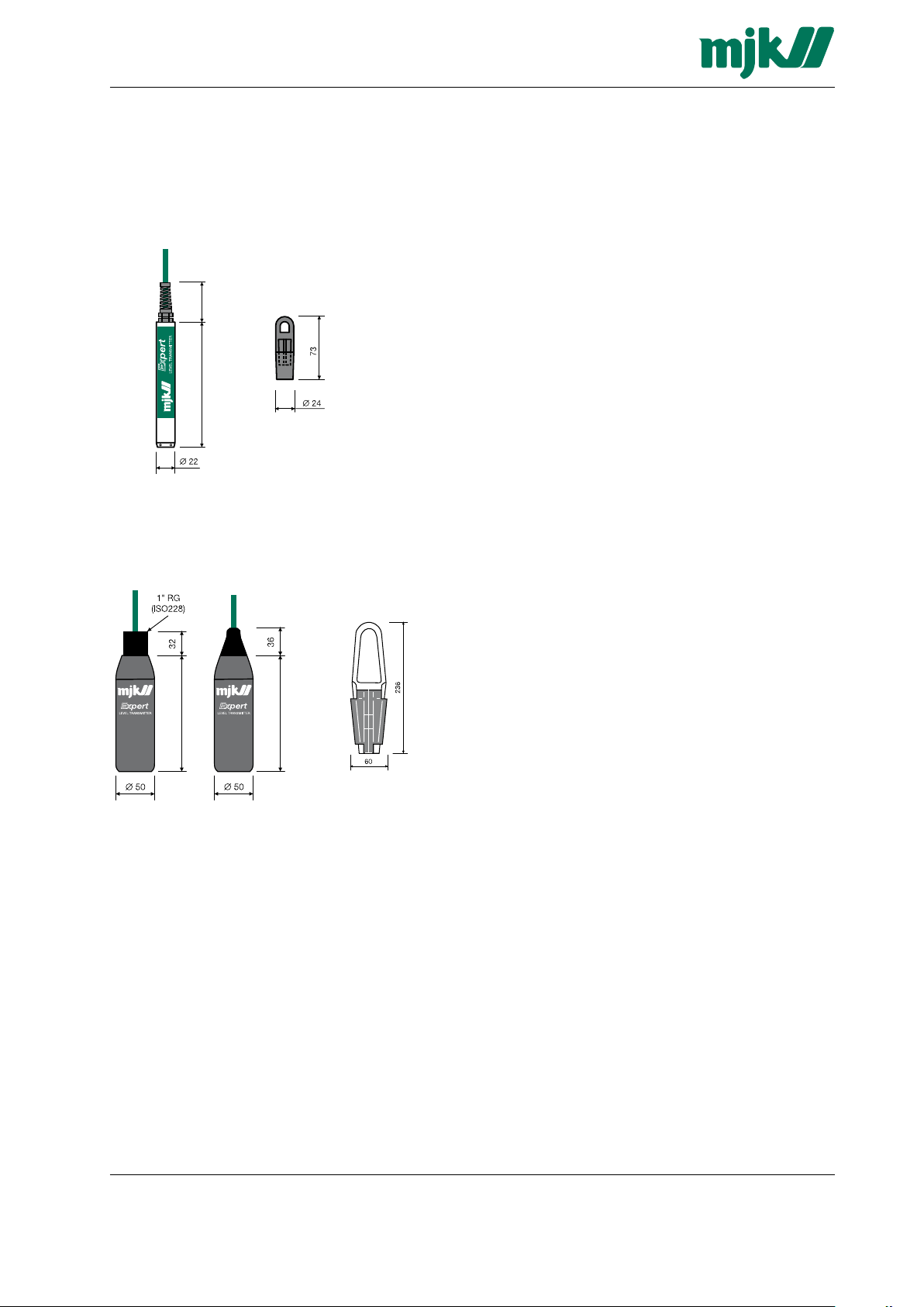
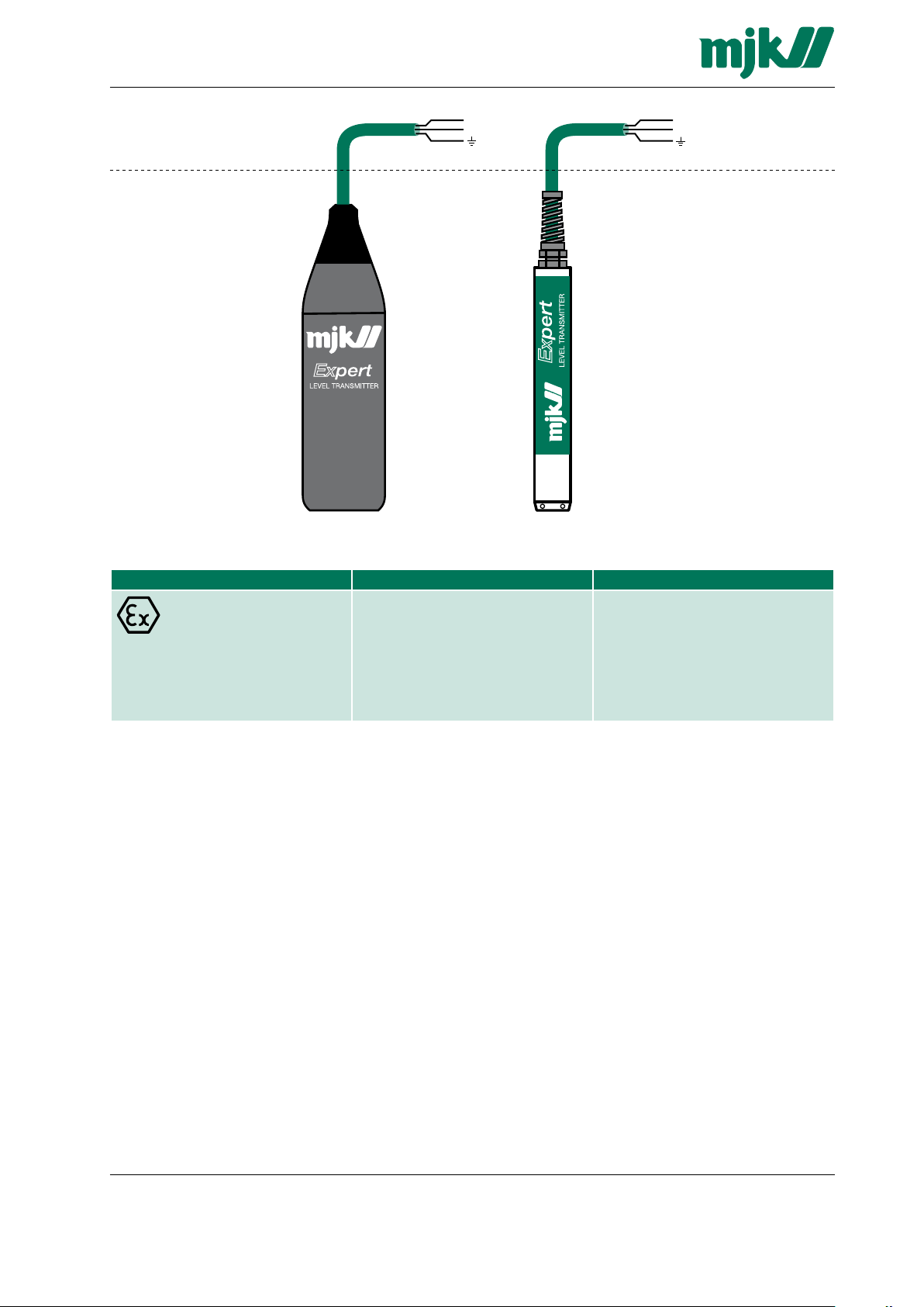
3400 transmitter
1400 transmitter