mk-messtechnik GmbH U8/12-1M User manual

Manual
BV15
Analog transmitter
U8/12-1M
Digital optical transmitter
for analog voltage signals


Inhaltsverzeichnis
1 Box contents.......................................................................................................................4
2 C aracteristics....................................................................................................................4
3 Field of application.............................................................................................................5
4 Maintenance....................................................................................................................... 5
5 Trouble s ooting.................................................................................................................6
6 Accessories / Options.........................................................................................................7
7 Contact...............................................................................................................................7
Appendix: Details..............................................................................................................A1

Date:
03.05.12
U8/12-1M
Page: 4 Manual
1 Box contents
Quantity Description
1 Transmitter U8/12-1M
1 Receiver U8/12-1M
1 optical fiber 62,5 / 125µm
2 C argers (or 1+1 power supply)
1 Manual (englis )
1 External battery pack1 (optional)
T e s ipment includes c arged batteries. However, due to t e self-
disc arging of NiMH-batteries t ey s ould be rec arged again before use.
Read c ap. 4 (Maintenance) before c arging t e devices!
2 Characteristics
T e U8/12-1M can be used to optically transmit analog voltage signals.
Because of t e optical transmission, t e system is very robust against EMS
(electromagnetic susceptibility). It can wit stand ig electric and
magnetic fields, like t ey appear in EMC-tests and also is optimized for low
noise emission.
T e standard voltage range of t e system is +/-15V. It is available in
numerous variants. For more information about t e variants, see
datas eet or call us.
Power is supplied by internal NiMH-batteries w ic make t e system easy
to use. T e U8/12-1M is prepared for t e use of external batteries (wit
optional battery pack).
mk-messtec nik GmbH - Zeppelinstr. 1 - 73274 Notzingen - Tel: +(49) 7021-9566925
Read c ap. 5 before
c arging!

U8/12-1M Date:
03.05.12
Manual Page 5
3 Field of application
•Transmission of analog signals during EMC-tests
•Transmission of analog signals over long distances wit out voltage
loss (up to 100m or more, depending on timing requirements)
•Handle ground potential problems
T e U8/12-1M as integrated filters enabling EMS and EMI testing. T ere is
no need for external filtering.
4 Maintenance
Rec arge batteries after use wit t e enclosed c arger. To prevent a lazy
battery effect, disc arge t e devices every 5 times completely by using t e
automatic switc off (Leave t e system on, until it turns off automatically).
Afterwards, c arge t e devices as usual.
T e devices ave to be turned off before connecting to t e c arger. If t is
is disregarded, t e system mig t get damaged!
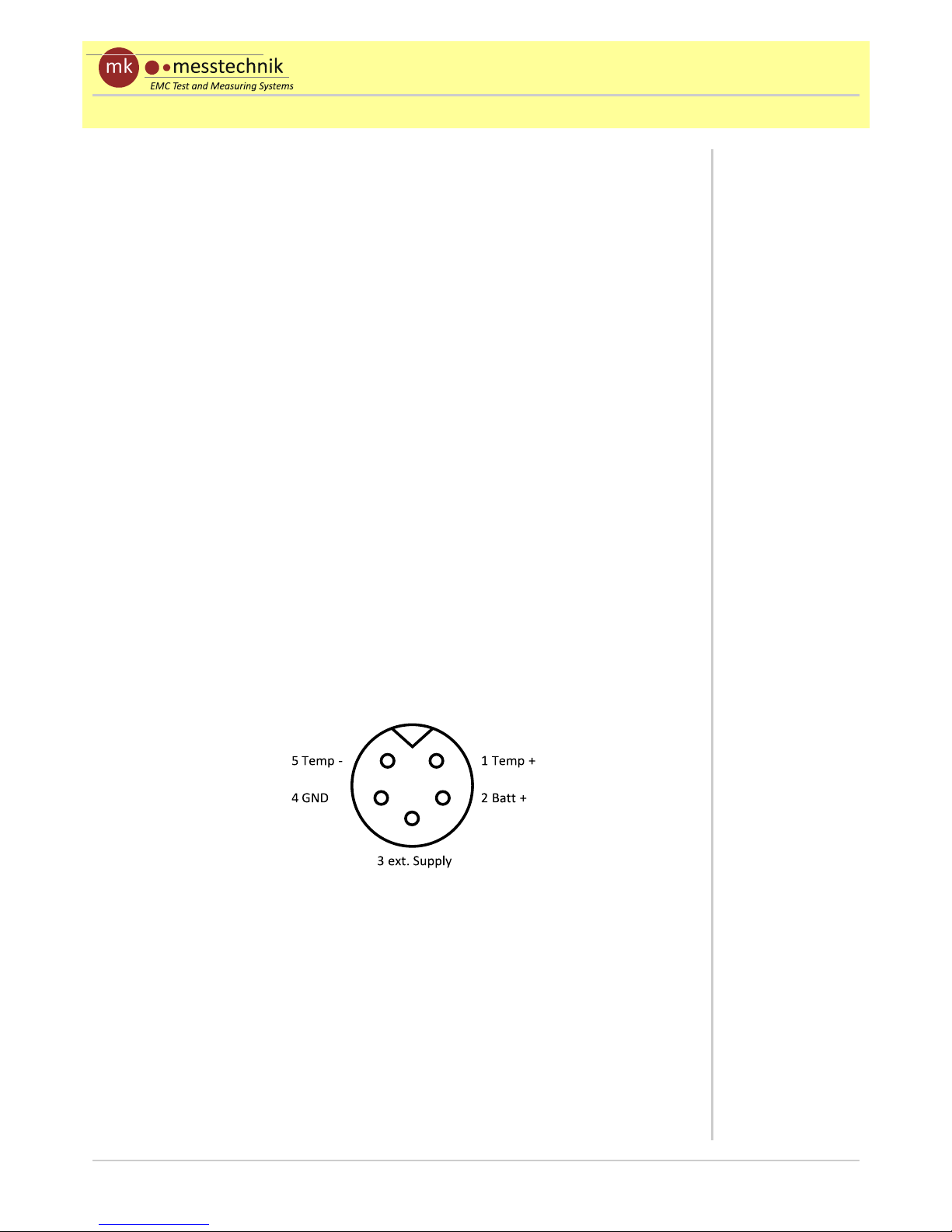
Fig. 4.1 s ows t e pinning of t e c arge connector. C argers ave to be
connected to pin 2 (+) and pin 4 (GND). An external supply (8-10V, 0.5A)
can be connected to pin 3 (+) and pin 4 (GND). se only power supplies
which are certified by mk-messtechnik.
T e included c argers are not meant to power t e transceivers during
operation. T e transceiver outside t e s ielded room can be run wit an
external power supply (optional). T e internal transceiver can be run wit
an external battery, if needed (optional). Do not use t e external power
supply or c arger to power t e transceiver inside t e s ielded room w ile
EMI-tests are running. T is mig t damage t e transceiver!
Due to self-disc arge issues wit NiMH batteries, rec arge batteries before
use, if t e system as not been used for a longer time.
mk-messtec nik GmbH - Zeppelinstr. 1 - 73274 Notzingen - Tel: +(49) 7021-9566925
Maximum c arging
current is 1 A
Fig. 4.1: Pinning of charge- / buffer connector
Do not use charger
or power supply
during EMI-test!
Devices must be
turned off before
connecting to
charger, or else the
system might get
damaged!
Pinning of c arge- /
buffer connector

Date:
03.05.12
U8/12-1M
Page: 6 Manual
Do not use cleaning agents or solvents to clean t e devices, only use a
slig tly moistened, soft clot .
Do not open t e devices, as t ere are no parts inside w ic ave to be
maintained. T e opened ousing can pose a fire azard t roug s ort-
circuit currents! Please contact your distributor or t e manufacturer if you
ave any problems. Send in t e complete system (bot transceivers), if a
problem cannot be solved by turning t e devices off and on again or by
c ecking t e positions of t e switc es. Please contact us in any case before
sending in t e devices.
5 Trouble shooting
T e following trouble s ooting list is provided to assist you w ile aving
problems. It mig t let you use t e system again wit out a long down time:
Error: Possible reasons: Solution:
No transmission, DC
voltage at output
No optical signal at t e
receiver
System (transmitter)
turned off
C eck optical fibers and
connections, c ange
fibers if necessary
Turn on t e devices,
take care of power-up
sequence
Transmission stops Low battery
Signal of source
interrupted
C eck LEDs at
transmitter and
receiver, rec arge
batteries
Test source signal
directly at t e device
under test
Device cannot be
turned on, cannot be
c arged
Batteries damaged
Internal fuse is broke
C arger or cable
damaged
Batteries
overdisc arged
Send in device to t e
manufacturer
Send in device to t e
manufacturer
C eck / replace c arger
C arge batteries, maybe
use ot er c arger (5
battery cells)
Output voltage does not
correspond to t e
expected value
Voltage divider was not
taken into account
Set / Include ratio at t e
oscilloscope
mk-messtec nik GmbH - Zeppelinstr. 1 - 73274 Notzingen - Tel: +(49) 7021-9566925
Do not open the
devices!
Short cut / fire
hazard!

U8/12-1M Date:
03.05.12
Manual Page 7
Error: Possible reasons: Solution:
Low-impedance at
input
Input wiring defective Send in device to t e
manufacturer
6 Accessories / Options
Part Order number Comment
Optical fiber LWL-1-xm x = lengt in m, simplex
External batteries BP-84 8,4V/4A
Connector cable for
BP-60
SC-20-5m-5m Lengt approx. 20cm
C arger wit
connector plugs CH-5 Standard c arger
Manual MA-U8/12-1M German or englis
7 Contact
mk-messtec nik GmbH
Zeppelinstraße 1
D-73274 Notzingen
Tel.: (+49) 7021 / 9566925
Mobil: (+49) 160 / 96205204
Fax: (+49) 7021 / 978206
Email: info@mk-messtec nik.de
www: www.mk-messtec nik.de
WEEE-Reg.-Nr. DE 21806070
mk-messtec nik GmbH - Zeppelinstr. 1 - 73274 Notzingen - Tel: +(49) 7021-9566925

Date:
03.05.12
U8/12-1M
Page: 8 Manual
mk-messtec nik GmbH - Zeppelinstr. 1 - 73274 Notzingen - Tel: +(49) 7021-9566925

U8/12-1M Date:
05/03/12
Manual - Appendix Page A1
Appendix: Details and operation
The following hapter is used to des ribe spe ial details of the U8/12-1M
system with 8 hannels (+/-15V) for unidire tional transmission.
a) Housing and connectors / switches
Fig. a.1 shows the ba k (left) and front (right) side of the transmitter with
onne tors and swit hes. It is set up in a shielded metal ase made to be
used inside an absorber lined hamber. It has integrated filters. The signals
an be onne ted dire tly to the BNC plugs at the ba k. To avoid
interferen es or other EMC issues, always use BNC ables as short as
possible to onne t your DUT.
•Signal onne tors BNC (In1 .. 8: +/-15V 1M
Ω
||10pF)
•Power push button with ontrol LED (Pwr On/Off)
•Battery information LED (Info)
•Charge plug (Charge)
•Opti al onne tor FSMA (Optica Out)
•PC USB onne tor, used for internal programming and firmware
updates, not ne essary for ustomer.
The housing of the BNC plugs is onne ted to the aluminum ase, whi h is
onne ted to the ir uit GND. This should be taken into a ount during the
test (possible ground loops, short ir uits, parasiti s to GND-plane!).
mk-messte hnik GmbH - Zeppelinstr. 1 - 73274 Notzingen - Tel: +(49) 7021-9566925
Fig. a.1: transmitter with connectors
Charge
Pwr Info
On/Off
Optical
Out PC
In 1
± 15 V 1 MΩ / 10pF
In 2 In 3 In
In 5 In 6 In 7 In 8
Transmitter
The BNC housings
have the same
potential as the
aluminum ase.

Date:
05/03/12
U8/12-1M
Page: A2 Manual - Appendix
Fig. a.2 and Fig. a.3 show the front and ba k side of the table top re eiver:
•Power swit h with ontrol LED (Power)
•Signa detect LED gives information about the working link to the
transmitter.
•Signal onne tors BNC (Ch 1 .. 8): +/-15V 10mA
•Opti al onne tor FSMA (Optica In)
•Power plug (DC In 9 .. 12V 1A)
mk-messte hnik GmbH - Zeppelinstr. 1 - 73274 Notzingen - Tel: +(49) 7021-9566925
Re eiver
Fig. a.2: Front side of tab e top receiver
Power
Ch 2Ch 1 Ch 3 Ch Ch 5 Ch 6 Ch 7 Ch 8
Signal Detect
U8/12-1M Receiver
Fig. a.3: Rear side of tab e top receiver
Optical In DC In
9..12 V
1 A
U8/12-1M-Receiver
S/N:
mk-messtechnik GmbH
Zeppelinstr. 1
7327 Notzingen
Germany
WEEE-Reg.-Nr. DE21806070
www.mk-messtechnik.com

U8/12-1M Date:
05/03/12
Manual - Appendix Page A3
b) peration and handling of the U8/12-1M
•Conne t the opti al fiber
•Conne t the analog signal ables to transmitter. It is re ommended
to hoose the ables as short as possible, sin e the transmitter input
(1MΩ || 10pF) is not mat hed to your appli ation (avoid
os illations).
•Conne t the output of the re eiver to a suitable high-impedan e
voltage measurement devi e, su h as an os illos ope or multimeter.
The length of the onne tor able should not be signifi antly longer
than 1m, sin e the upper frequen y limit is lowered by the parasiti
apa itive load.
•Set the voltage measurement devi e to the expe ted voltage and
time range, if ne essary. If used, take optional in luded voltage
divider into a ount, while setting / he king your measurement
devi e.
•Plug in power supply of the re eiver.
•Turn on all devi es (no order to be re ognized). Communi ation
between transmitter and re eiver will be indi ated by the Signal
dete t LED at the re eiver.
•The U8/12-1M system is ready to use about two se onds after
turning on the transmitter.
•Che k info LED if transmission stops suddenly!
If the transmission suddenly stops after a long duration of measurement,
he k the Info LED of the transmitter (see Figure a.1). If the battery power
falls below 7,2V, the Info LED is swit hed on. The system should be
reloaded soon. Below 5,8V, the system is turned off automati ally.
The measurements an be extended by using the optional battery pa k
(BP-84) with onne tor able or a power supply ertified by mk-
messte hnik. The external supply an be onne ted to the system any time
(parallel). The onne tion to the internal battery is de oupled with a diode.
Only use the battery pa k and onne tor ables from mk-messte hnik!
Others might lead to a damage of the system!
mk-messte hnik GmbH - Zeppelinstr. 1 - 73274 Notzingen - Tel: +(49) 7021-9566925
Check info LED if
transmission stops
suddenly!
nly use battery
packs and connector
cables provided
from mk-
messtechnik. ther
modules influence
EMS-performance
and might damage
the opto-system!

Date:
05/03/12
U8/12-1M
Page: A4 Manual - Appendix
mk-messte hnik GmbH - Zeppelinstr. 1 - 73274 Notzingen - Tel: +(49) 7021-9566925
Table of contents
Popular Transmitter manuals by other brands

Valcom
Valcom T7C Series manual

AUREL
AUREL TX1-HCS-433 instruction manual

Becker
Becker Centronic VarioControl VC421A Assembly and operating instructions

Williams Sound
Williams Sound T1-216 Specification sheet

Masibus
Masibus TT7S00-HR-S user manual

Badger Meter
Badger Meter Data Industrial 340 BN/MB Installation & operation manual