MKN HansDampf 6.1 User manual

Service manual
Service manual & wiring diagrams
Electric and Gas Combisteamer Silver II
European CE-Version
2010/02/23 SEV/KA
Model Serial-No. / date
Csxxxxx From U to
HansDampf 6 1 07020766 / June 2007
HansDampf 6 2 Maxi 07020584 / June 2007
HansDampf 10 1 07020584 / June 2007
HansDampf 10 2 Maxi 07020584 / June 2007
HansDampf 20 1 07020584 / June 2007
HansDampf 20 2 Maxi 07020584 / June 2007
1

Service manual
Overview of the error messages
Error message Description
Err 1
Error core temperature probe
Err 2
Error chamber probe 1
Err 3
Error chamber probe 2
Err 4
Core temperature probe not calibrated
Err 5
Error drain probe
Err 7
Error reference probe on board defect
Err 8
Risk of ice
Err 9
Overtemperature cooking chamber
Err 10
Overtemperature electronic
Err 11
Electronic too hot
Err 20
Core temp replace not possible
Err 30*
No fan 1
Err 31*
Fan runs
Err 32*
No fan 2
Err 33*
Fan direction wrong
Err 36*
Jumper setting at frequency controller wrong
Err 40
Not authorized access
Err 66**
No water
Err 71*
No gas 1
Err 710*
No gas 2
Err 72*
No gas fan 1
Err 720*
No gas fan 1
Err 73*
General gas fault 1
Err 730*
General gas fault 2
Err 74*
No flame 1
Err 740*
No flame 2
Err 101***
Battery empty
Err 120
12 Volt ground error
Err 121
UREF0 Ground error at probe or pcb
SHO
Demo mode
-n-
Emergency program
-c-
Carry out unit configuration in the service area
*= Only at Gas units
**= Only at units with WaveClean
***= Only at units with gas and communication pcb
2

Service manual
Contents
Overview of the error messages 2
Overview of the technical features & options HansDampf Silver 2 5
Keypad and displays of the HansDampf Silver 2 6
Functional diagram of the DynaSteam technology 7
The automatic cleaning system WaveClean 8
How to open the Front Panel and the Side Walls 6 x – 20 x 12
Basics of the gas technology 13
CO2 value calibration 16
Gas orifices and fan speeds 20
Internal gas supply check 21
Check-up of the connection pressure (operating pressure) 22
Rearrangement of the gas type 23
Adjustment of the cooking chamber door for 6 x up to 20 x 24
DynaSteam unit documentation 25
Description of the frequency controller 28
The main menu (Password overview & Diagnosis memory) 30
Service menu HansDampf Silver 31
Settings area (basic settings) 46
Layout of the control pcb Silver2 (Electric-Version) 49
Layout of the control pcb Silver2 (Gas-Version) 51
Layout of the gas- und communication pcb Silver 2 53
Fuse protection schematic for CE Electric units 54
Fuse protection schematic for CE Gas units 55
Rewiring and reprogramming manual at use of the reserve relay K 23 56
Continuation rewiring and reprogramming the reserve relay 57
How to activate and disable the demo mode 58
Appendix A: Wiring diagram #209367 for HansDampf Silver 2 electric (6 x – 20 x)
Appendix B: Wiring diagram #209370 for HansDampf Silver 2 gas (6 x – 20 x)
3

Service manual
4

Service manual
Overview of the technical features & o tions HansDam f Silver 2
Technical feature
HansDampf silver
Electric
HansDampf silver
Gas
Contactor controlled fan motor X
Frequency controlled fan motor X
Three-phase motor
without fan speed-sensor X
Frequency controlled motor
with fan speed sensor X
Gas- and communication pcb O tion X
Manual cleaning program Only if unit is not
equi ed with
WaveClean
o tion
Only if unit is not
equi ed with
WaveClean
o tion
Automatic cleaning system
WaveClean (two pumps, trap) O tion O tion
DynaSteam steaming unit X X
Pressure switch at the
DynaSteam steaming unit
Only at o tion
WaveClean
Only at o tion
WaveClean
Four point core temp probe O tion O tion
Tube shower integrated O tion O tion
DryTronic
(Fresh air pipe with lift magnet) O tion O tion
Back ventilated chamber door X X
Triple glazed camber door O tion O tion
This overview exclusively contains equipment/additional functions relevant for the service
Reserved for changes
5

Service manual
Key ad and dis lays of the HansDam f Silver 2
6

Service manual
Functional diagram of the DynaSteam technology
With automatic cleaning system WaveClean
Without automatic cleaning system WaveClean
The graphics shows units with the optional DryTronic system (Fresh air pipe with lift magnet)
7

Service manual
DynaSteam Features
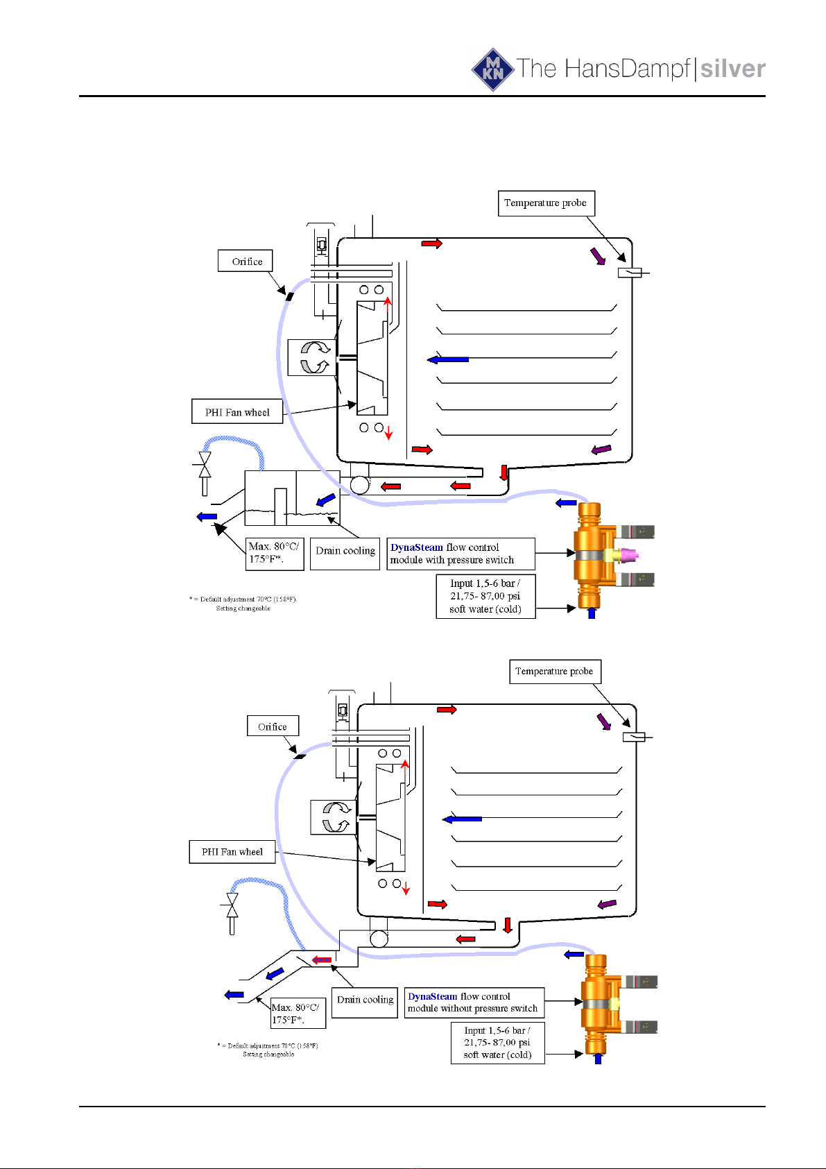
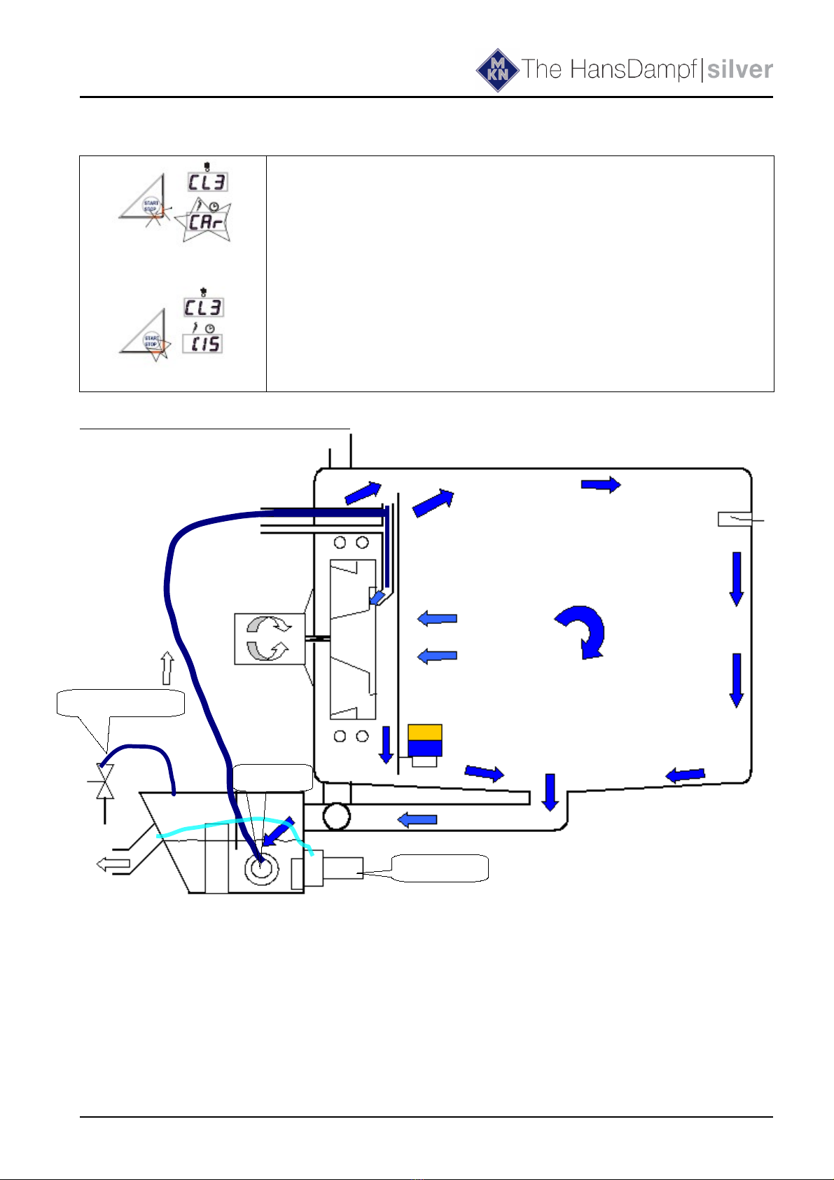
➢The pcb controls the DynaSteam unit which is responsible for the amount of injected water
The incoming water flow pressure must be between 1,5 (21,75 psi) and 6 bar (87,00 psi) The
pressure switch controls the availability and the pressure of water (Only at units with
WaveClean)
➢The water runs now through a hose to the water supply pipe located in the chamber Inside the
hose is an orifice to stabilize the pulsed water flow from the DynaSteam unit
➢The water supply pipe injects the water on an centrifuge at the PHI fan wheel The heating
elements surround the fan wheel heats it up The water gets to steam now and by the speed of
the fan wheel tiny drops are flung against the chamber Surplus water runs into the drain
➢During heat up and after opening / closing the door during operation the steaming unit
increases the amount of water to speed up the steam production (controlled by the electronic)
➢At a temperature of more than 107°C (225°F) the steaming unit decreases the amount of water
(electronic controlled)
Average water consumption
during permanently steaming:
unit / type 6 23 6 1 6 2 10 1 10 2 20 1 20 2
steam water
volume in ml/h
7500 16000 21000 18000 24000 18000
18000
24000
24000
The automatic cleaning system WaveClean
Option
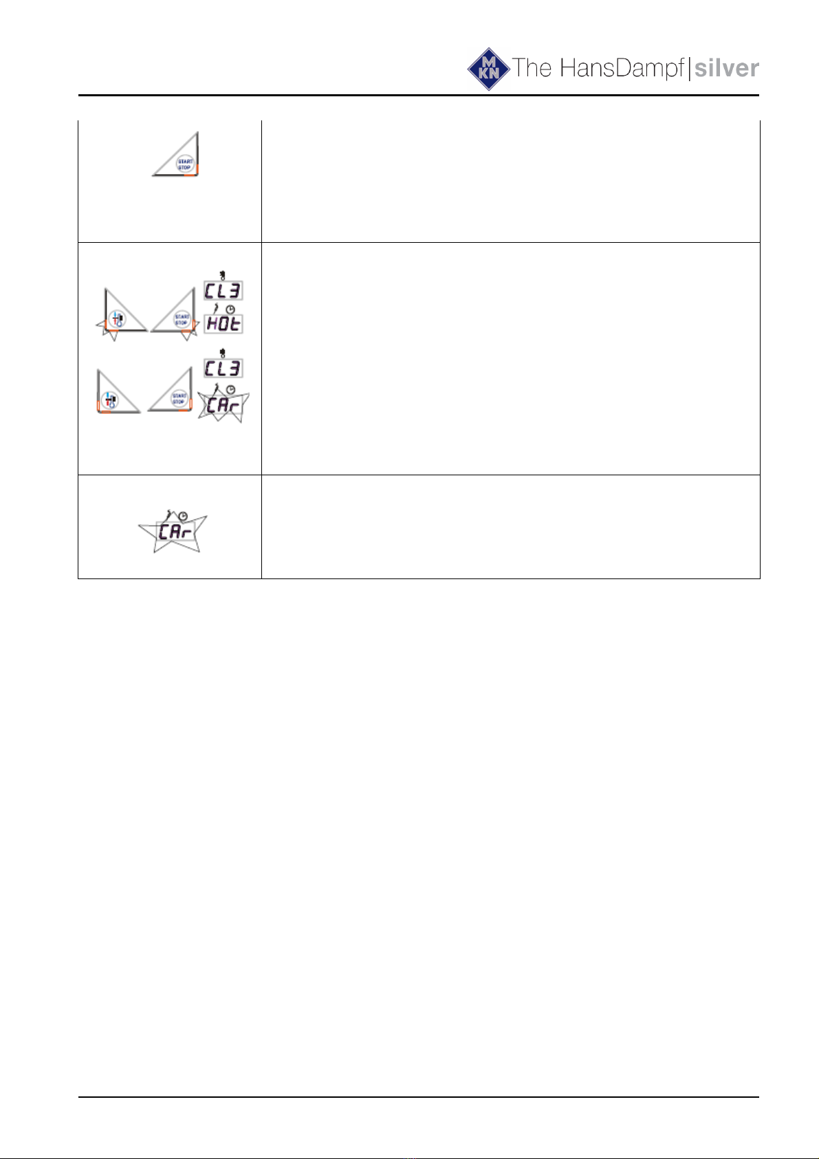
Selecting cleaning level and starting WaveClean
➢Press the "FLEXI" button after switching on the Combisteamer or
when a cooking process is complete
➢The upper display shows CL
➢The bottom display remains dark
➢Press the START/STOP button
➢ CL1 is displayed in the top display for the first WaveClean
cleaning stage
Select the cleaning stage with the adjustment knob:
CL1 -> WaveClean, short : approx 1,0 Std
CL2 ->WaveClean, normal: approx 2,0 Std
CL3 -> WaveClean, extra: approx 3,0 Std
Staring WaveClean Press the "START/STOP" button after selecting the
8

Service manual
cleaning stage If the cooking chamber is too hot
when starting occurs, it is cooled down first (see
"Cooking chamber too hot")
If the cooking chamber is at the starting temperature,
cooling is skipped and insertion of the cartridges is
continued (see "Inserting cartridge")
Chamber to hot WaveClean does not start until the cooking chamber
temperature is 50 °C or below
If the temperature in the cooking chamber is over
50 °C, it is automatically cooled
• Hot appears in the upper display
• Preheat and Start/Stop button flashing
The signal is sounded briefly when the start
temperature is reached
• Preheat and Start/Stop button are off
• Car flashes in the bottom display
Insert cartridge The flashing information CAr in the bottom display prompts the insertion
of the cartridge
9

Service manual
Continuation Description WaveClean II
Close the door again::
➢The START/STOP button illuminates and the Combisteamer
is ready for operation (standby)
➢The upper display shows the cleaning stage
➢The bottom display shows Car flashing
Start WaveClean by pressing the START/STOP button:
➢The START/STOP button flashes
➢The upper display shows the cleaning stage, e g CL3.
➢The bottom display shows the remaining cleaningtime
(countdown)
Schematic diagram exam le 6.x / 10.x
1
Solenoid valve Y12
Pump M16
Pump M24

Service manual
Continuation Description WaveClean II
Ste by ste descri tion
Step Description
01 - Depending on exit temperature the chamber cooling down to 55°C (131°F)
02 - Cleaning of the siphon by water exchange The pump M24 pumps out the water from
the siphon The siphon gets filled with water about the solenoid valve Y12 This
process recurs repeatedly This process serves for cleaning the siphon
03 - Double pre-cleaning of the chamber by changing the water radically above pump
M16
04 - Cleaning starts after a time of 6 minutes The chamber heated at the same time The
cleaner activates at a temperature of 70°C (158°F) A cancellation of the cleaning
process is not possible in this phase!
05 - Execution of cleaning The fan runs in right/left direction The pump M16
permanently changes the water radically The running time depends on the chosen
cleaning program
06 - Cleaning of the siphon by water exchange The pump M24 pumps out the water from
the siphon The siphon gets filled with water about the solenoid valve Y12 The
process recurs repeatedly This process serves for cleaning the siphon Fresh water is
changed radically over the pump M16 to rinse the chamber The fan runs in right/left
direction
07 - The chamber heats up to 92°C (198°F) The rinse wax layer smelting now The rinse
granulate falls into the chamber now A cancellation of the cleaning process is not
possible in this phase!
08 - The rinsing program starts The fan runs in right/left direction The pump M16
permanently changes the water radically The running time depends on the chosen
cleaning program
09 - Cleaning of the siphon by water exchange The pump M24 pumps out the water from
the siphon The siphon gets filled with water about the solenoid valve Y12 This
process recurs repeatedly This process serves for cleaning the siphon Fresh water is
changed radically over the pump M16 to rinse the chamber The fan runs in right/left
direction
10 - The oven starts in steam mode for four minutes to prepare final rinsing After this the
final rinsing starts
11 - The chamber dried with hot air for 10 minutes Thereby the chamber heats up to
105°C (221°F)
When cleaning with "short-program" this step is skipped.
12 - The device turns off itself now Cleaning is finished
Note:
During cleaning approx 3 litres of water are led through the soft water assembly group to rinse out
possible cleaner delays
At an interruption of the power supply the cleaning process stopped automatically A cancellation
program which rinses out the cooking chamber is started with a duration of 12 minutes
This program is carried out also at a manual cancellation
An entry is written down in the diagnostic memory
11

Service manual
How to o en the Front Panel and the Side Walls 6.x – 20.x
Removing side walls:
After dismounting of the two (four) screws, the respective side wall can be removed
➢At the gas units (6 x, 10 x) are two additional screws on top of the left side wall
➢The 20 x freestanding unit has additional screws in the center area of each side wall
O ening the Front Panel::
The Front Panel will be unlocked by turning the hexagon socket (size 5) clockwise Lift up the Front
Panel careful and open it
12
Hexagon socket
unlock
lock
2 screws 2 screws
2 screws (only at
Gas units) 2 screws
Hexagon socket
unlock
lock

Service manual
Gas technology
Basics of the gas technology
Operation of the gas burner:
The electronic (pcb) gives a heat demand (relay K14 and K15) to the burner control
The electronic (pcb) regulates the speed of the gas fan and supervises these
The complete igniting process is handled by the burner control
At a failure of the flame signal from the burner control to the electronic the appliance is
nevertheless ready for use There is an electrical failure of the signal which safety-related is
quite safe as long as no alarm is reported (The burner control has recognized the flame (In this
case there is "just"an error to transmit information to the electronic The burner control itself
has already detected the flame)
Functional diagram
13

Service manual
The gas fan
The gas fan promotes the air-/ gas mixture into the burner The promoting volume and the performance
are dependent on the speed of the gas fan This is steered and supervised by the electronic The speed
only can be changed in a defined speed window which is dependent on the kind of gas and unit size
The speed window is basis of the equipment admittance and may not be changed This regulation
ensures that the gas fan speed works independently of outer influences (temperature and supply
voltage)
Fan speed control:
The gas fan is / are controlled by a PWM signal (pulse width modulation) from the electronic A2,
terminal X8 2 (6 x, 10 x, lower chamber at 20 x) and terminal X8 4 (upper chamber at unit size 20 x)
Without PWM signal and with available supply voltage the gas fan runs for safety reasons with full
speed The gas fan transmit the fan speed to the electronic A3, terminal X5 2 (6 x, 10 x, 20 x lower
chamber) and terminal X5 5 (only 20 x upper chamber) as a re-registration The gas blower is
regulated on set rotation speed by a software regulator This can be checked with the help of the
configuration menu (service menu)
A speed fluctuation up to 50 rpm is normal
14

Service manual
The ignition electrode
The ignition electrode serves to ignite the gas/air mixture and is supplied by a separate transformer
The flame control
The flame control induces an ionization current (approx 5 µA) after the igniting process and passes
this to the burner control If this confirmation is not available, the error message Err 71 (no gas)
appears and a reset of the burner control is necessary
The overlap-time
A sufficient overlap-time is important to ensure for a safety ignition process This time can be
controlled in the generally measurement mask
When heating request of the temperature regulator is available, the display changes from G0 to G1
At first F0 is still shown because there is no flame detected At latest after 7 seconds F1 must be
shown on display, otherwise appears the error message Err 71 (no gas)
If the "flame OK" signal is permanently not available the unit goes into an emergency program,
because there is no safety risks represents
In this case F0 does not change to F1 into the measurement mask, even though the flame is present
(The unit heats up) There is only a risk / error, if within the heat demand (active operating) the "flame
OK signal" changes repeatedly from F1 to F0
15

Service manual
CO2 value calibration
6 x–20 x Gas
Basics
Definition of CO2 (carbon dioxide) and CO (carbon monoxide):
Carbon dioxide is a colourless and odourless gas and supplies a chemical union made of carbon and
oxygen Carbon dioxide arises at the burning of substances containing carbon (gasses) if enough
oxygen is available At an oxygen deficiency CO (carbon monoxide) arises CO is a color- and
odourless, poisonous gas which can lead to death!
CO2 value calibration
Caution: This adjustment is crucial for the safe operation of the appliance After leak testing, the CO2
content of the exhaust gas requires calibration and the CO content is to be checked
Select CO2 value calibration menu
➢Switch the unit with the ON/OFF Button on
➢Press the Flexi Button
➢The upper display shows the first menu CL or CLE
➢Choose Par (Parameter) with the upper knob and
press the Start/Stop button
➢The upper display shows PAS (Password)
➢The lower display shows 0
➢Enter password 999 with the lower knob and press the
Start/Stop button
➢ CO2 upper display
➢The lower display shows a flashing Hi and at two
chamber units Hi1 for the upper chamber (20 x)
➢It is possible to switch with the lower knob between
high power (Hi, Hi1, Hi2) and low power (Lo,
Lo1, Lo2 )
Note for two chamber units::
Hi1 / Lo 1 = 20 x, upper chamber (burner)
Hi2 / Lo 2 = 20 x, lower chamber (burner)
16

Service manual
Start the CO2 calibration
The C02 has first to be measured at high power After
selecting Hi, Hi1, Hi2 press the START/STOP button
➢The LED of the START/STOP-button flahes
➢The upper display shows CO2
➢In the lower display Hi, Hi1 or Hi2 flashes
Burner status
After starting the CO2-calibration the preheat button has to
be pressed
➢At one chamber units (6 x, 10 x) 6F is displayed in the
upper display and on two chamber units (20 x)
6F or 6F2 is displayed 6F1 represents the upper
chamber and 6F2 represents the lower chamber The
two chambers are calibrated separately
➢For an error free starting procedure 00, 10, 11 is
displayed in the lower display 0 = not present or active,
1 = present or active The digit below the G and F
(or F1, F2) represents its status Indicating first no
operation, then gas valved opened and within 6 seconds
the flame has to be sensored otherwise the procedure is
stopped with error Err 71
Error during start rocedure
If the flame was not detected within 6 secondes after the gas
valve was opened the procedure is stopped and the error
Err 71 is displayed Please check that an external gas
valve is opened If a unit is started for the first time this error
occurs serval times until the air in the gas pipe is flushed out
➢In the upper display Err (Error) flashes
➢In the lower display the error code is displayed In
this case 71
➢The step button flashes
➢Press the step button to confirm the error and restart
the procedure by pressing the "Start/Stop" button
17

Service manual
Continuation C 2 calibration
Cooking chamber tem erature
After the burner has ignited (lower display shows 11)
press the preheating button to show the cooking
chamber temperature
➢The upper display shows the actual cooking chamber
temperature e g 85 (°C/°F)
➢The lower display shows the rpms of the gas blower
divided by 10 e g 280 for 2800 rpm
CO2 measurement
If the cooking chamber has a approximate temperature
of 15 °C and the rpm show the values according
to the table check the CO2 value.
Fan speed in rpm for high (Hi) power and low power (Lo)
Model Hi, Hi1, Hi2 Lo, Lo1, Lo2
6 1 5050 4800
6 2 6700 5300
10 1 5050 2800
10 2 6700 2800
20 1 5050 2800
20 2 6700 2800
Place the CO2 probe into the exhaust pipe For correct
measurement do not place the probe during the ignition
process Be sure to place the probe into the correct
pipe for two chamber models The C02 value has
to be within the range according to the table Take
care that the cooking chamber temperature does not
exceed 200°C If the temperature reaches 250°C the
procedure is automatically stopped
18

Service manual
After measuring the CO2 value at maximum power
switch the units to low power (Lo, Lo1; Lo2)
The upper display shows CO2
Turn the lower knob to Lo, Lo1 or Lo2 and press
the FLEXI button to activate the low power mode If
the FLEXI button is not pressed within 5 seconds
the prior mode is still active
The lower displays shows Lo, Lo1 or Lo2
The rpm´s of the gas blower shows the values
according to the rpm table
The CO2 content at low power has to be 0,5-1% lower than at high power This is for a safe operation
of the appliance crucial The CO content has to be always lower than 100 ppm (Except during the
ignition phase), otherwise the appliance is not allowed to operate On the two chamber models the
chambers are calibrated separately and can be toggled by turning the lower knob until the desired
chamber and power is displayed Then press the FLEXI button for confirmation
The upper chamber is active when Hi1 or Lo1 is displayed and the lower chamber is active when
Hi2 or Lo2 is displayed Be sure to have the CO2 probe in the correct exhaust pipe
Changing lower power CO2 values
If the measured value differs from the values given in
the table, the CO2 content must be adjusted to match
the values given in the restrictor table The unit was
designed in that way that the CO2 values at high
power are automatically within the range If this is not
the case the installed orifice is wrong or the caloric
heat value of the gas is not normal With the
adjustment screw [1] the CO2 for high power can be
influenced
Unscrew the cap [1] on the gas valve and adjust the
CO2 content using the adjustment screw (white
plastic) behind it during low power operation Refit the
metal cab after calibration is finished
If the low power CO2 value has been changed, the
CO2 values at high power has to be checked again
If the CO2 content at high power is too high or too low
please check that the correct orifice is installed The
CO2 content at high power can be reduced by using
the adjustment screw [2] It has to be turned inwards
to reduce the CO2 at high power
19

Service manual
Gas orifices and fan s eeds
2
This manual suits for next models
5
Table of contents
Other MKN Electric Steamer manuals