Mobiclinic ATLAS User manual

Instrucciones en Español
User manual in English
ES
EN
Última revisión: 1 de Septiembre 2021
Last revision date: September 1st 2021
Guarde el manual para futuras consultas
Safe this manual for future reference
Manual de instrucciones
Elíptica / Elliptical machine
ATLAS

ÍNDICE
1. Precauciones
2. Diagrama de piezas
3. Lista de piezas
4. Lista de componentes y piezas
4. Instrucciones de montaje
6. Funcionamiento del monitor
7. Solución de problemas
9. Recomendaciones - calentamiento y enfriamiento
1
2
3
4
5
8
9
9
ES

ES
1. Precauciones
Para reducir el riesgo de lesiones graves, lea todo el manual antes de ensamblar u operar la elíptica. En particu-
lar, tenga en cuenta las siguientes precauciones de seguridad.
1. Es su responsabilidad asegurarse de que todos los usuarios del equipo estén infor-
mados de todas las advertencias y precauciones.
2. Sea consciente de las señales de su cuerpo. Un ejercicio incorrecto o excesivo
puede perjudicar su salud. Deje de hacer ejercicio si experimenta alguna anomalía.
3. Mantenga a los niños y a los animales domésticos alejados del equipo. El equipo
está diseñado para uso exclusivo de adultos.
4. Utilice el equipo en una superficie sólida y plana, con una cubierta protectora para
el suelo o la alfombra. Por seguridad, el equipo debe tener al menos 0,5 metros de
espacio libre a su alrededor.
5. Antes de utilizar el equipo, compruebe que el manillar, el asiento, los pedales y las
tuercas y tornillos están bien apretados. El nivel de seguridad del equipo sólo puede
mantenerse si se examina periódicamente para detectar daños y/o desgaste. Preste
atención a la comprobación del punto de conexión y de las piezas del engranaje antes
de su uso para evitar peligros.
6. Lleve ropa adecuada mientras utiliza el equipo. Evite llevar ropa suelta que pueda
quedar atrapada en el equipo o que pueda restringir o impedir el movimiento.
7. El equipo ha sido probado y certificado según la norma EN957 bajo la clase H.C, apto
sólo para uso doméstico. Peso máximo del usuario: 100kg/225lbs. El frenado es inde-
pendiente de la velocidad.
8. El equipo no es apto para uso terapéutico.
9. Debe tener cuidado al levantar o mover el equipo para no lesionarse la espalda. Uti-
lice siempre técnicas de elevación adecuadas y/o utilice ayuda.
Advertencias
Utilice siempre el equipo como se indica. Si encuentra algún componente defectuoso
durante el montaje o la comprobación del equipo, o si escucha algún ruido inusual
procedente del equipo durante su uso, deténgase. No utilice el equipo hasta que el
problema haya sido subsanado.
Cuando quiera desechar la máquina, deberá retirar las baterías del ordenador y des-
echarlas por separado como residuo peligroso depositándola en su correspondiente
contenedor.
1

2. Diagrama de piezas
2
1
2
3
4
5
6
7
6
7
8
8
10
11
12
13R
13L
14R
14L
15
16
17
18
18
20
19
19
21 22
22
22
23
24
25
26
27
28
29
30
30
31
32
33
34
35
36
7
37
38
39
42
42
43
44 45
46
47
48
49
50
51
51
52
9
9
55
54
40
41
53
6
7
ES

ES
3. Lista de piezas
3
11
12
13R
13L
14R
14L
15
16
17
18
19
20
21
22
23
24
25
26
27
Nº
1
2
3
4
5
6
7
8
9
10
Nombre Nombre
NºQ Q
1
1
2
1
2
8
12
4
2
1
1
1
1
1
1
1
4
4
4
2
2
1
1
4
1
1
1
1
2
Bastidor principal
Estabilizador trasero
Tapa trasera
Estabilizador delantero
Tapa frontal
Tuerca abombada M8
Arandela curva de 8MM
Tornillo M8*60
1/2 arandela
1/2 tuerca nylock(L)
1/2 TUERCA NYLOCK(R)
Manivela
Cubierta de la cadena(L)
Cubierta de la cadena(R)
1/2 perno del pedal (L)
1/2 perno del pedal (R)
Arandela elástica 10MM
Tuerca M10
Arandela de 10MM
Pedal
Círculo de nylon
Tubo del pedal(R)
Tubo del pedal (L)
Arandela ondulada 16MM
Barra inferior del manillar (L)
Barra inferior del manillar(R)
Barra de la manilla (R)
Barra de la manilla (L)
Tornillo M10*25
28
29
30
31
32
33
34
35
36
37
38
39
40
41
42
43
44
45
46
47
48
49
50
51
52
53
54
55
Arandela elástica 10MM
Arandela de 10MM
Tornillo carro M8*40
Eje
Tornillo M8*15
Cable sensor inferior
Cable sensor superior
Gancho tensión inferior
Cable tensión superior
Poste delantero
Pomo de tensión
Tornillo M5*10
Ordenador
Cable del sensor
Tornillo M10*50
Empuñadura
Tapa del extremo
Manillar fijo
Empuñadura
Arandela de 8MM
Tornillo M8*25
Sensor de pulso
Cable de pulso
Arandela "D"
Arandela elástica 8MM
Cable de pulso
Tapón final
Tapón final
2
2
4
1
4
1
1
1
1
1
1
4
2
2
1
2
2
4
4
2
2
2
2
2
4
2
1
2

ES
4 . Lista de componentes y piezas
4
R
L
R
L
X1 X1 R/L
X1 X1 X1 X2
R/L X1 X1
AX4
CXR/L X1
X2
GX1
X1
X1
BX4
DX4
EX4
FX2

ES
5 . Instrucciones de montaje
5
PASO 1
PASO 2
1235
4OK
81
6
B
X2
Desembale la parte trasera y saque con cuidado las piezas.
De acuerdo con el plano de piezas de la página 3, ensamble los dos
estabilizadores traseros(2) y el bastidor principal (1) con la arandela
curva de 8MM(7) del perno de carro M8*60 (8), luego apriételos con una
llave.
Ajuste la perilla de tensión (38),
luego conecte el cable del sensor
inferior (33) con el superior (34), y
el gancho de tensión inferior (35)
con el superior (36) de acuerdo
con el de montaje.
Usando la arandela curva de
8MM (7), la arandela de presión
de 8MM (52) y el tornillo
M8*15(32) ensamble el poste
delantero (37) al marco principal
(1), luego apriete con la llave.

ES
6
PASO 3
PASO 4
R
L
R
L
X2
X1
X1
CXL
CXR
L
L
R
R
X1
R
D
L
D
Utilice el tornillo M10*25 (27), la
arandela elástica de 10MM (28), la
arandela de 10MM (29), arandela
"D" (51) y arandela ondulada (22)
de 16MM para ensamblar el eje
(31) y el poste (37), luego apriéte-
los con la llave. Ensamble el tubo
del pedal (20,21) y la manivela (12)
con 1/2 perno del pedal (14R,14L),
arandela ondulada de 16MM (22),
círculo de nylon (19), 1/2 arandela
(9) y y 1/2 tuerca nylock(10,11),
luego apriete con la llave.
Use X1 para ensamblar la barra de
la manija (25,26) y la barra de la
manija inferior (24,23) con M8
tuerca abombada, la arandela
curva de 8MM(7) y el tornillo de
carro M8*40(30), luego apriete
con la llave.

ES
7
PASO 5
PASO 6
X1
E
E
F
G
X2
Use X1 en el dibujo para ensam-
blar la barra de la manija(25,26) y
la barra de la manija infe-
rior(24,23) con tuerca abombada
M8(6), arandela curva 8MM(7) y
tornillo de carro M8*40(30), luego
apriete con la llave.
De acuerdo con el ejemplo de la
figura, pase los tres cables de
impulso de (50)a través del agu-
jero del poste delantero(37),
luego ensamble el manubrio
fijo(45) y el poste delantero (37)
con la arandela de 8MM(47) y tor-
nillo M8*25(48), luego apriételos
con una llave.

ES
6. Funcionamiento del monitor
8
PASO 7
ESCÁNER
TIEMPO
VELOCIDAD
DISTANCIA
CALORIAS
PULSO
TIPO DE BATERÍA
TMP. FUNCIONAMIENTO
TMP. ALMACENAMIENTO
Cada 6 segundos
0:00 ~ 99:59
0.0 ~ 99.9 KM/H (MILLA/H)
0.00 ~ 99.00 KM (MILLA)
0.0 ~ 999.9 CAL
60 ~ 240 BPM
2x AA o UM - 3
0ºC ~ +40ºC
-10ºC ~ +60ºC
FUNCIÓN
MODE - Presione hacia abajo para seleccionar las funciones. Presione hacia abajo
para restablecer el tiempo, la distancia y las calorías durante 2 segundos.
SCAN: Pulse el botón MODE hasta que aparezca "SCAN", el monitor rotará a través de
las siguientes funciones: tiempo, velocidad, distancia, calorías y pulso, cada pantalla
se mantendrá 6 segundos.
TIEMPO: Cuenta el tiempo total desde el inicio del ejercicio hasta el final.
VELOCIDAD: Muestra la velocidad actual.
DISTANCIA / CALORIAS: Cuenta la distancia / calorías desde el inicio del ejercicio
hasta el final.
PULSO: mide el pulso cardiaco. Mantenga los dos sensores de ritmo cardíaco en
ambas manos para medir el ritmo cardíaco.
Nota: Durante el proceso de medición del pulso, debido al atasco de los contactos, el
valor de la medición puede ser mayor que la frecuencia del pulso virtual durante los
primeros 2~3 segundos, luego volverá al nivel normal. El valor de la medición no
puede considerarse base de un tratamiento médico
AAA
X1
NOTA:
1. Si el símbolo de la batería en la pantalla se ilumina, por
favor, sustituya la batería.
2. El monitor se apagará automáticamente si no se recibe
ninguna señal después de 2 minutos y se encenderá
automáticamente cuando comience a ejercer la señal del
botón de entrada.
3. Cuando deje de hacer ejercicio durante 4 segundos, la
pantalla dejará de calcular y se mostrará un "STOP" en la
pantalla. Cuando empiece a hacer ejercicio, la pantalla
empezará a calcular automáticamente y el "STOP"
desaparecerá.
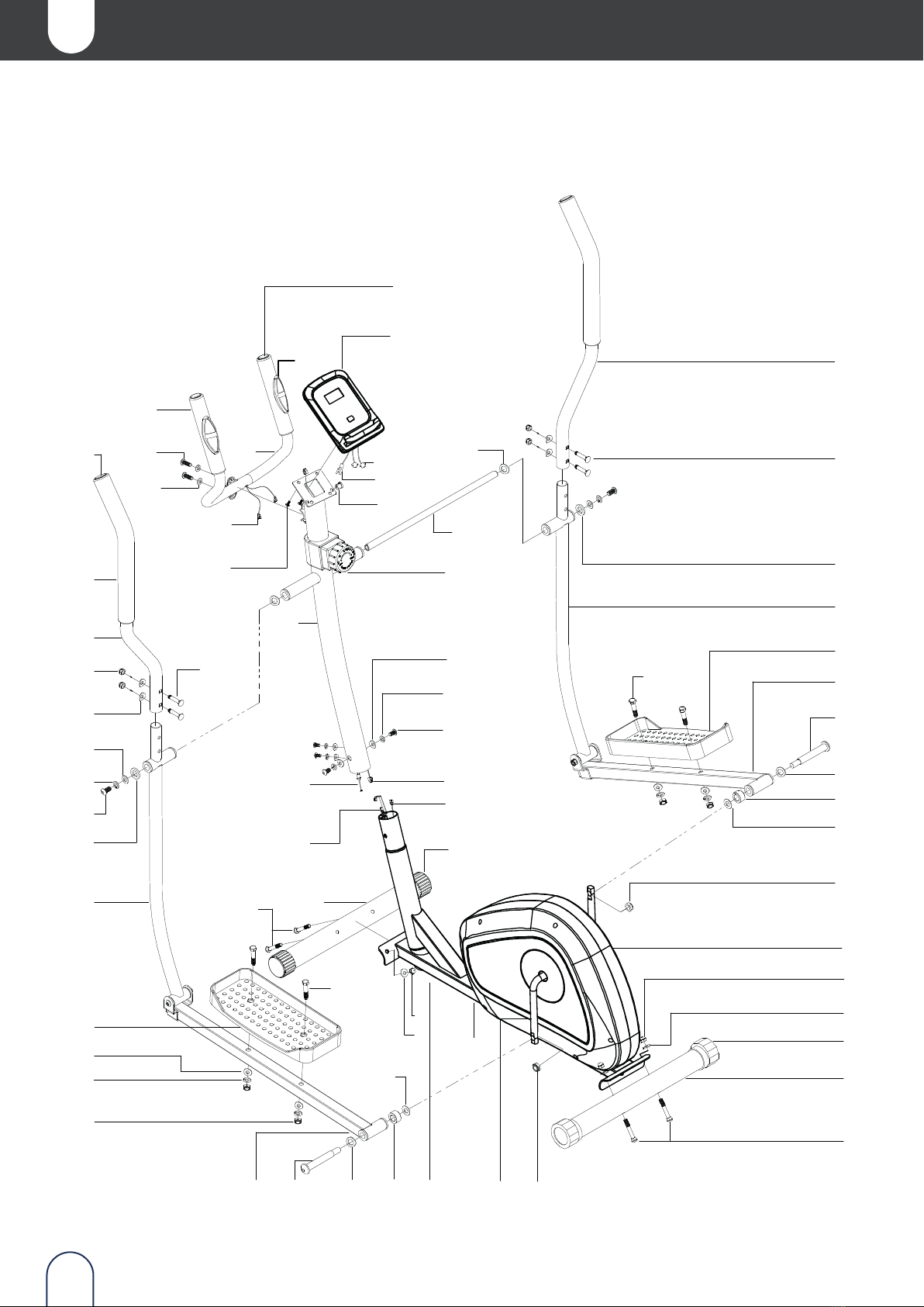
Conecte el cable de impul-
sos (53) del ordenador (40) y
el cable de impulsos (50) del
manillar fijo (45).
Coloque las pilas adecuadas
en el estuche de las pilas.
Monte el ordenador (40) y el
poste delantero (37) con el
tornillo M5*10(39) y el tapón
final, luego apriételos con
una llave.

8. Recomendaciones - calentamiento y enfriamiento
ES
7. Solución de problemas
9
A continuación se recomienda los siguientes ejercicios con una duración de 30 seg
para cada uno. No fuerce el ejercicio durante el estiramiento, en caso de dolor,
detenga el movimiento.
1. Cambio de la batería. Deslice el ordenador por el soporte, retire la tapa de la bate-
ría en la parte posterior de la consola del ordenador y retire las baterías. Sustitúyalas
por pilas AAA. Vuelva a colocar la tapa en la consola y deslice el ordenador de nuevo
en el soporte.
2. El ordenador no funciona correctamente. Compruebe si el cable del sensor inferior
está conectado al superior, y que este último está conectado al ordenador. Si sigue
sin funcionar, asegúrese de que las pilas están instaladas correctamente en el orde-
nador y que funcionan.
3. No hay resistencia. Si no hay resistencia a la tensión en la bicicleta, asegúrese de
que el cable de tensión superior esté conectado al cable de tensión inferior.
FLEXIÓN LATERAL MUSLO EXTERIOR
MUSLO INTERIOR
FLEXIÓN HACIA
DELANTE
BECERRO / AQUILES

EN
INDEX
1. Precautions
2. Parts diagram
3. Parts list
4. Components and parts list
4. Assembly instructions
6. Operation of the monitor
7. Problems solution
9. Recommendations - warm up and cool down
1
2
3
4
5
8
9
9

EN
1. Precautions
To reduce the risk of serious injury, read the entire manual before assembling or operating the folding magne-
tic exercise bike. In particular, observe the following safety precautions.
1
1. It is your responsibility to ensure that all users of the equipment are informed of all
warnings and cautions.
2. Be aware of your body's signals. Incorrect or excessive exercise can damage your
health. Stop exercising if you experience any abnormality.
3. Keep children and pets away from the equipment. The equipment is designed for
adult use only.
4. Use the equipment on a solid, flat surface with a protective floor covering or carpet.
For safety, the equipment must have at least 0.5 metres of free space around it.
5. Before using the equipment, check that the handlebars, seat, pedals, nuts and bolts
are tightened securely. The safety level of the equipment can only be maintained if it
is regularly inspected for damage and/or wear. Pay attention to checking the connec-
tion point and gear parts before use to avoid hazards.
6. Wear suitable clothing while using the equipment. Avoid wearing loose clothing
that may get caught in the equipment or that may restrict or impede movement.
7. The equipment has been tested and certified to EN957 under class H.C, suitable for
domestic use only. Maximum user weight: 100kg/225lbs. Braking is independent of
speed.
8. The equipment is not suitable for therapeutic use.
9. Care must be taken when lifting or moving the equipment to avoid back injury.
Always use proper lifting techniques and/or use assistance.
Warnings
Always use the device as described. If you find any defective components during
assembly or testing of the equipment, or if you hear any unusual noise coming from
the equipment during use, stop using the equipment. Do not use the equipment
until the problem has been rectified.
When you want to dispose of the machine, you must remove the batteries from the
computer and dispose of them separately as hazardous waste in the appropriate
container.

2. Diagram of parts
2
1
2
3
4
5
6
7
6
7
8
8
10
11
12
13R
13L
14R
14L
15
16
17
18
18
20
19
19
21 22
22
22
23
24
25
26
27
28
29
30
30
31
32
33
34
35
36
7
37
38
39
42
42
43
44 45
46
47
48
49
50
51
51
52
9
9
55
54
40
41
53
6
7
EN

EN
3. Parts list
3
nº Name qty Nº Name qty
1 Main frame 1 28 10MM spring washer 2
2 Rear stabilizer 1 29 10MM washer 2
3
Rear end cap
2
30
Carriage bolt M8*40
4
4 Front stabilizer 1 31 axle 1
5
Front end cap
2
32
Screw M8*15
4
6
M8 domed nut
8
33
Lower sensor wire
1
7 8MM curved washer 12 34 Upper sensor wire 1
8
Carriage bilt M8*60
4
35
Lower tension hook
1
9
1/2 washer
2
36
Upper tension wire
1
10
1/2 nylock nut(L)
1
37
Front post
1
11
1/2 NYLOCK NUT(R)
1
38
Tension knob
1
12
Crank
1
39
Screw M5*10
2
13R Chain cover(L) 1 40 computer 1
13L Chain cover(R) 1 41 Sensor wire 1
14R
1/2 pedal hinger bolt(L)
1
42
Screw M10*50
4
14L 1/2 pedal hinger bolt(R) 1 43 Form grip 2
15
10MM spring washer
4
44
End cap
2
16
M10 nylock nut
4
45
Fixed handlebar
1
17 10MM washer 4 46 Form grip 2
18
pedal
2
47
8MM washer
2
19
Nylon circle
2
48
Screw M8*25
2
20 Pedal tube(R) 1 49 Pulse sensor 2
21 Pedal tube(L) 1 50 Pulse wire 2
22
16MM waved washer
4
51
“D” washer
2
23 Lower handle bar(L) 1 52 8MM spring washer 4
24
Lower handle bar(R)
1
53
Pulse wire
2
25
Handle bar(R)
1
54
End plug
1
26 Handle bar (L) 1 55 End cap 2
27
Screw M10*25
2

EN
4 . Components and parts list
4
R
L
R
L
X1 X1 R/L
X1 X1 X1 X2
R/L X1 X1
AX4
CXR/L X1
X2
GX1
X1
X1
BX4
DX4
EX4
FX2

EN
5 . Assembly instructions
5
X1
AA
STEP 1
STEP 2
1235
4OK
81
6
B
X2
Unpack the rear part and carefully remove the parts.
According to the parts drawing on page 3, assemble the two rear stabili-
zers(2) and the main frame (1) with the 8MM curved washer(7) of the
M8*60 carriage bolt (8), then tighten them with a spanner.
Adjust the tension knob (38),
then connect the lower sensor
cable (33) to the upper sensor
cable (34), and the lower tension
hook (35) to the upper tension
hook (36) according to the moun-
ting bracket.
Using the 8MM curved washer
(7), 8MM lock washer (52) and
M8*15 bolt (32) assemble the
front post (37) to the main frame
(1), then tighten with the spanner.

EN
6
STEP 3
STEP 4
R
L
R
L
X2
X1
X1
CXL
CXR
L
L
R
R
X1
R
D
L
D
Use the M10*25 bolt (27), 10MM
spring washer (28), 10MM washer
(29), "D" washer (51) and 16MM
wave washer (22) to assemble
the axle (31) and post (37), then
tighten them with the spanner.
Assemble pedal tube (20,21) and
crank (12) with 1/2 pedal bolt (14)
with 1/2 pedal bolt (14R,14L),
16MM wave washer (22), nylon
circle (19), 1/2 washer (9) and 1/2
nylock nut (10,11), then tighten
with spanner.
Using X1 in the drawing to assem-
ble the handle bar(25,26) and
lower handle bar(24,23) with M8
dished nut(6), 8MM curved was-
her(7) and M8*40 carriage bol-
t(30), then tighten with spanner.

EN
7
STEP 5
STEP 6
X1
E
E
F
G
X2
Using X1 in the drawing to assem-
ble the handle bar(25,26) and
lower handle bar(24,23) with
M8(6) countersunk nut, 8MM(7)
curved washer and M8*40(30)
carriage bolt, then tighten with
spanner.
According to the example in the
figure, pass the three drive
cables (50) through the hole of
the front post (37), then assemble
the fixed handle (45) and the
front post (37) with the 8MM
washer (47) and M8*25 bolt (48),
then tighten them with a span-
ner.

EN
6. Operation of the monitor
8
STEP 7
SCAN
TIME
SPEED
DISTANCE
CALORIES
PULSE
BATTERY TYPE
OPERATING TMP.
STORAGE TMP.
Every 6 seconds
0:00 ~ 99:59
0.0 ~ 99.9 KM/H (MILE/H)
0.00 ~ 99.00 KM (MILE)
0.0 ~ 999.9 CAL
60 ~ 240 BPM
2x AA o UM - 3
0ºC ~ +40ºC
-10ºC ~ +60ºC
FUNC-
TION
MODE - Press down to select functions. Press down to reset time, distance and calo-
ries for 2 seconds.
SCAN: Press the MODE button until "SCAN" appears, the monitor will rotate through
the following functions: time, speed, distance, calories and pulse, each display will be
held for 6 seconds.
TIME: Counts the total time from the start of the exercise to the end.
SPEED: Displays the current speed.
DISTANCE / CALORIES: Counts distance / calories from the start of the exercise to the
end.
PULSE: Measures heart rate. Hold both heart rate sensors in both hands to measure
heart rate.
Note: During the process of pulse measurement, due to the jamming of the contacts,
the measurement value may be higher than the virtual pulse rate for the first 2~3
seconds, then it will return to the normal level. The measurement value cannot be
considered as the basis for medical treatment.
AAA
X1
NOTE:
1. If the battery symbol on the display is illuminated,
please replace the battery.
2. The monitor will automatically turn off if no signal is
received after 2 minutes and will automatically turn on
when it starts to exercise the input button signal.
3. When you stop exercising for 4 seconds, the display
will stop calculating and a "STOP" will be shown on the
display. When you start exercising, the display will start
calculating automatically and the "STOP" will disappear.
Please connect the pulse
wire (53) of computer(40)
and pulse wire (50) of fixed
handlebar(45).
Put the right batteries into
the battery case. Assemble
the computer (40)and front
post (37)with Screw M5*10
(39) and end plug,then tigh-
ten them with a wrench.
Other manuals for ATLAS
1
Table of contents
Languages:
Other Mobiclinic Elliptical Trainer manuals