Mobile Solutions PT-9A+ User manual

LINE OUT SPEAKER
HIGH LEVEL INPUT
- +
PT-9A+
POLARITY +
POLARITY -
LOW BATTERY
CD LINE
SIGNAL
ON OFF
POWER
OUT IN
Version 1.0
Many “Real World” Uses:
Check Speaker Connecons
Check Absolute Speaker Polarity
Check Passive Crossover Phase Shi
Check OEM Amplier Outputs
Idenfy Channel (No more drill baeries)
Check for Speaker Mounng Leaks
.......and so much more!
PT-9A+ Polarity Tester
Professional Speaker Calibration and Polarity Test Instrument
User Manual
MOBILE SOLUTIONS USA
2120 E. 6th Street, Suite 10
Tempe, AZ 85281
email - sales@mobilesoluons-usa.com
www.mobilesoluons-usa.com

PT-9A+ Polarity Test Instrument
The PT-9A+ Polarity Tester is an essenal measurement tool for building and tuning great car audio systems. Please read
the user manual carefully and follow the instrucons provided.
What is the Overall Goal?
The goal of any audio system with mulple speakers is to reproduce sound energy so that the absolute phase between all
speakers is complimentary (rather than destrucve). This means all speakers in the system need to be working together.
The PT-9A+ allows the install technician to verify the absolute phase of each speaker in the system, both individually and
as a group using a combinaon of internally generated pulses and pulses from the test tracks contained on the included
USB thumb drive.
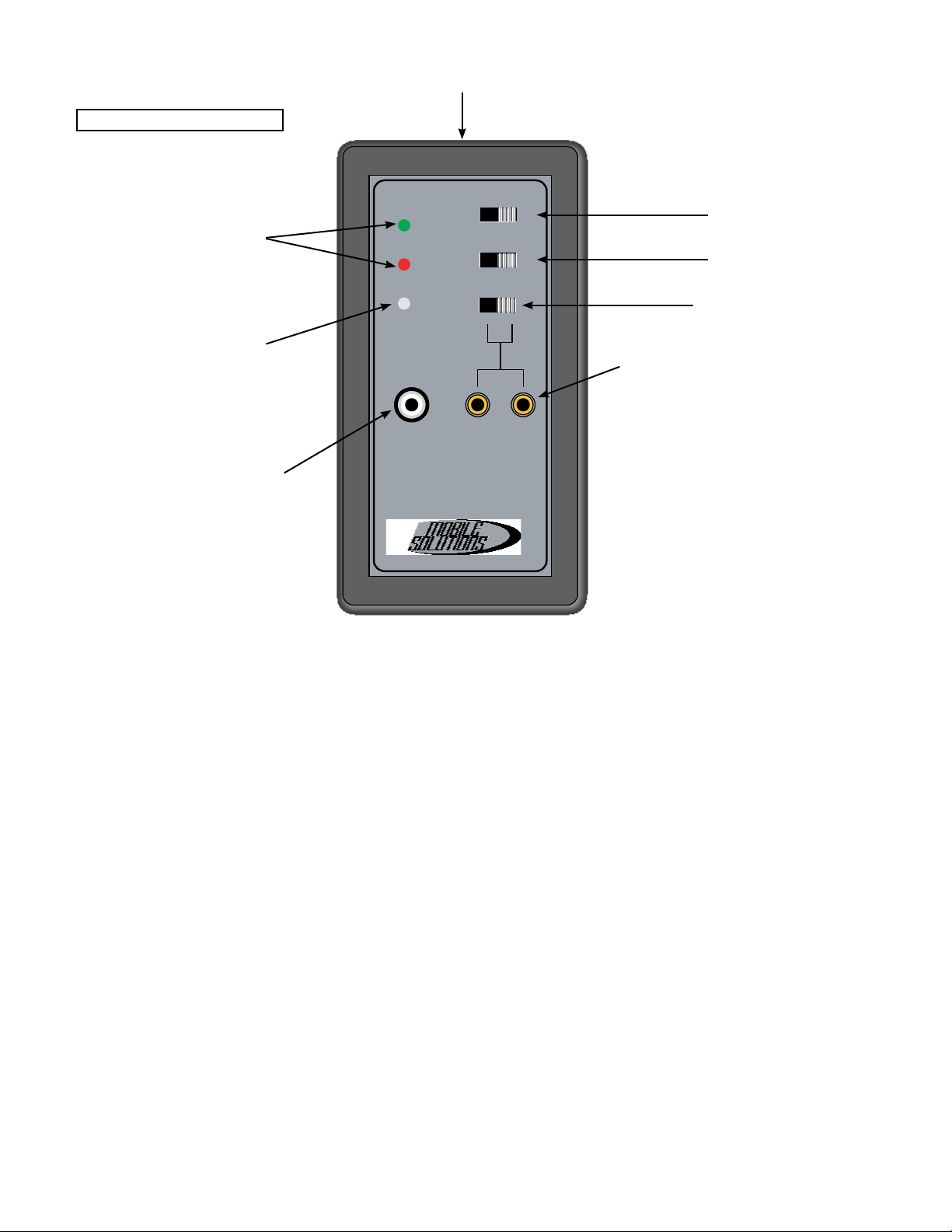
Simple GREEN or RED light pulses on the front of the instrument indicate the overall condion of the speaker(s) being
evaluated in real me while installed in their nal posion(s) in the vehicle. It can’t get much more accurate than that!
FEATURES
Internal Pulse Generator
The PT-9A+ features an internal pulse generator output that simultaneously processes speaker pulses through the built-in
microphone located on the front of the instrument. This allows the unit to be enrely self contained. The internal genera-
tor provides evenly spaced, posive (pressure) pulses to both the line level jack and speaker level outputs for the duraon
of me the unit is on. The LINE LEVEL signal is sucient to drive signal processor and amplier inputs. The SPEAKER LEVEL
signal is sucient to drive a speaker directly. To use the internal pulse generator, be sure the IN/OUT switch is in the OUT
posion and the SIGNAL switch is in the LINE posion.
Alternavely, the PT-9A+ can use only the built-in microphone with the SIGNAL switch is in the CD posion to “hear” pulses
generated by an external source, such as the pulse tracks provided on the included USB thumb drive. You can also download
the pulses from the Mobile Soluons website and use a portable device (such as a smartphone) to generate pulses in the
audio system.
Internal Pulse Reader
The PT-9A+ also funcons as a pulse reader. The speaker jacks can be congured to accept speaker-level INPUT up to 4VAC
to idenfy the electrical polarity of an audio signal. This feature allows the technician to determine which wire is posive
(+) and negave (-) so that, when doing an OEM audio integraon job, the inputs to a DSP or amplier can be congured
correctly with respect to polarity.
Test the outputs of an OEM source unit or OEM amplier when the speakers in the vehicle have already been disconnected
and removed. To use the internal pulse reader, be sure the IN/OUT switch is in the IN posion and the SIGNAL switch is
in the LINE posion.
Test Tracks
The included USB thumb drive contains a polarity pulses track to be used in conjuncon with the PT-9A+. The sequence on
the pulse track is three (3) POSITIVE pulses followed by one (1) NEGATIVE pulse. When wired correctly and responding in
absolute phase, speakers tested in the system should show three (3) GREEN lights followed by one (1) RED light on PT-9A+.
To use only the built-in microphone and pulses from an external source, move the SIGNAL switch into the CD posion.
Pink Noise tracks are also included on the USB thumb drive or available for download. These are intended for use with a
Real-Time Analyzer (RTA) to help with system tuning. One each le and right side mono pink noise track, along with a mono
pink noise track for le and right channels combined.
Noise Free Testing Zone
It’s very important that this instrument is used in an environment where there is not a high level or external ambient noise
when checking the speaker polarity using the built-in microphone. Installaon bays can contain a high level of noise during
a producve day, so you may wish to close the vehicle doors and ask others nearby to minimize unnecessary noise. This
will only help the accuracy of the built-in microphone.

Operating Instructions
Verify an individual preamp-level (RCA) polarity using Internal Pulse Generator
1) Move the Signal Switch of the test instrument to the “LINE” posion.
2) Switch ”SPEAKER/HIGH LEVEL INPUT” buon to ”OUT”.
3) Connect one RCA audio cable to the instrument’s “LINE OUT” RCA jack. This can be the input cable to a signal processor
or amplier. Test only one channel at a me.
• The orientaon of polarity on the “LINE OUT” RCA jack is posive (+) on the center pin and negave (-) on the
outer shield.
4) Ensure the processor or amplier is turned on so signal can pass from that component’s input through the audio signal
path and ulmately to the speaker(s) connected on that channel.
5) Move the Power Switch of the test instrument to the “ON” posion.
6) Point the polarity tester’s front panel microphone about 2-4 inches from the cone (or grille) of the speaker you wish to
test. You should hear a faint pulsing sound from the speaker.
7) Based on the orientaon of the RCA LINE OUT jack as described in Step 3, a GREEN light indicates the speaker is in cor-
rect polarity with the RCA input of the device tested. A RED light indicates the speaker’s polarity is backward (reversed)
from the device’s input polarity.
• If the RED LED illuminates, this means the speaker is wired backward, the input signal to (such as in OEM audio
integraon) is backward or the input of the device has an internal polarity reversal seng. Check and verify each
of those scenarios that apply, make any necessary changes and test again.
• If GREEN and RED LEDs are both lit AT THE SAME me it may indicate a leaky speaker mount.
8) Repeat for other individual speakers as needed.
LINE OUT SPEAKER
HIGH LEVEL INPUT
- +
PT-9A+
POLARITY +
POLARITY -
LOW BATTERY
CD LINE
SIGNAL
ON OFF
POWER
OUT IN
Built-in Microphone on Front of Instrument
(Position no more than 4” from front of speaker for accurate reading)
Polarity Indicators
Green = Positive (Pressure)
Red = Negative (Vacuum)
Signal Switch
Power Switch
Low Battery Indicator
(Illuminates Yellow when
9.6v battery requires
replacement)
Line Level Output Pulse Generator
(Output Pulse is active when
the Signal Switch is in the LINE
position)
Dual Function Speaker Level Jacks
1)Output Pulse is active when the
Signal Switch is in the LINE position
and the IN/OUT Switch is in the OUT
position
2) Input Pulse Sensing is active
when the Signal Switch is in the
LINE position and the IN/OUT Switch
is in the IN position
Front Panel Layout
IN/OUT Switch

Alligator Clip to Probe Side Alligator Clip to Backpin Probes
Verify an individual speaker’s polarity using Internal Pulse Generator
1) Move the Signal Switch of the test instrument to the “LINE” posion.
2) Switch ”SPEAKER/HIGH LEVEL INPUT” buon to ”OUT”.
3) Connect the probes to the speaker’s terminals. Red probe to + terminal and Black probe to - terminal.
4) Move the Power Switch of the test instrument to the “ON” posion.
5) Point the polarity tester’s front panel microphone about 2-4 inches from the cone (or grille) of the speaker you wish to
test. You should hear a faint pulsing sound from the speaker.
6) Based on the orientaon of the probes as described in Step 3, a GREEN light indicates the speaker is in correct polarity
with the posion of posive and negave probes. A RED light indicates the speaker’s polarity is backward (reversed).
• If the RED LED illuminates, this means the speaker is wired backward. Switch wiring and test again.
• If GREEN and RED LEDs are both lit AT THE SAME me it may indicate a leaky speaker mount.
7) Repeat for other individual speakers as needed.
Note - if using in an OEM audio integraon applicaon where you are pulsing the wires in a factory head unit or amplier
harness (unplugged) to nd the speaker locaons, you may wish to use smaller “backprobe pin” type leads and clip onto the
PT-9A+ test leads with an alligator clip as shown in the photos. This will eliminate any unnecessary damage to high density
OEM wiring and connectors in the plug.
Verify Acoustic Signal polarity using Polarity Pulse Test Track
1) Insert USB thumb drive with included polarity pulse track.
2) Move the Signal Switch of the test instrument to the “CD” posion.
3) Switch ”SPEAKER/HIGH LEVEL INPUT” buon to ”OUT”.
5) Move the Power Switch of the test instrument to the “ON” posion.
6) Play the polarity pulse track. Set volume where pulses are just audible.
7) Point the polarity tester’s front panel microphone about 2-4 inches from
the cone (or grille) of the speaker you wish to test.
8) Evaluate your results:
• Three (3) GREEN lights followed by one (1) RED light indicates the
speaker wiring is in correct polarity.
• Three (3) RED lights followed by one(1) GREEN light indicates the
speaker wiring is in incorrect (reversed) polarity. This can also occur
(typically on a tweeter) when using a 12dB/octave passive crossover
network. Check the speaker individually rather than at the input of
the crossover if this is the case.
• If GREEN and RED LEDs are both lit AT THE SAME me it may indicate
a leaky speaker mount.
USB
LINE OUT SPEAKER
HIGH LEVEL INPUT
- +
PT-9A+
POLARITY +
POLARITY -
LOW BATTERY
CD LINE
SIGNAL
ON OFF
POWER
OUT IN
Source Unit

To purchase other test leads and acoustic/electronic measurement
equipment, please contact MOBILE SOLUTIONS USA
sales@mobilesoluons-usa.com or visit us on the web - www.mobilesoluons-usa.com
Verify individual speaker-Level Electrical Signal polarity using Internal Pulse Reader
Note: This test assumes the system’s speakers have already
been disconnected or they are not yet installed.
1) Insert USB thumb drive with included polarity pulse
track.
2) Move the Signal Switch of the test instrument to the
“CD” posion.
3) Switch ”SPEAKER/HIGH LEVEL INPUT” buon to ”IN”.
4) Connect the probes to the speaker wiring you wish to
test. Connect the Red probe to what you believe is the
posive( +) speaker wire and what you believe is negave
(-) speaker wire.
5) Move the Power Switch of the test instrument to the
“ON” posion.
6) Play the polarity pulse track. Set volume where pulses are just audible.
7) Based on the orientaon of the probes as described in Step 4:
• Three (3) GREEN lights followed by one (1) RED light indicates the speaker wiring is in correct polarity with the
posion of posive and negave probes.
• Three (3) RED lights followed by one (1) GREEN light indicates the speaker wiring is in incorrect (reversed) polarity
with the posion of posive and negave probes. Switch the probes on the speaker wiring and test again.
PT-9A+ Technical Specifications
• Output Pulse Voltage (RCA Jack) 0.05VAC RMS
• Output Pulse Voltage (Speaker Jacks) 1.5VAC RMS
• Output Pulse Duration (RCA or Speaker Jacks) 70mS (0.07 Second)
• Max Input Voltage (Speaker Jacks) 4V
• Speaker Jack Spacing 0.59” / 15mm
• Test Probe Leads for Speaker Jacks 4mm Banana w/Silicone Wire
• Power 9V Battery (not included)
• Weight (including battery, case & probes) 10.8oz / 305g
OEM
OEM
Source Unit
Amplifier
LINE OUT SPEAKER
HIGH LEVEL INPUT
- +
PT-9A+
POLARITY +
POLARITY -
LOW BATTERY
CD LINE
SIGNAL
ON OFF
POWER
OUT IN
USB
LINE OUT SPEAKER
HIGH LEVEL INPUT
- +
PT-9A+
POLARITY +
POLARITY -
LOW BATTERY
CD LINE
SIGNAL
ON OFF
POWER
OUT IN
Table of contents
Popular Test Equipment manuals by other brands

VeEX
VeEX UX400 user manual

Cannon
Cannon TE-BBR instruction & operation manual

PCB Piezotronics
PCB Piezotronics 482C26 Installation and operating manual

norbar
norbar 43222 installation guide

pico Technology
pico Technology PicoScope 6000 Series user guide

Vigor Equipment
Vigor Equipment V 2459 Application note

Hanna Instruments
Hanna Instruments Groline HI981030 user manual

MULTI MEASURING INSTRUMENTS
MULTI MEASURING INSTRUMENTS MCL-800D instruction manual

PDK
PDK PCS-P100 user manual

Trifitek
Trifitek TR-550 manual

Panasonic
Panasonic DP-100 series instruction manual

Hanna Instruments
Hanna Instruments HI 38076 instruction manual