Mobiltech ZEUS200 User manual

Thermoelectric Generator
INSTALLATION MANUAL
ZEUS200 BD
Power Supply: Diesel
IMPORTANT
As reported in the warranty conditions available on our
website, the warranty becomes void if the instructions in the
installation manual are disregarded.
More information can be found on chapter 6 of this manual.

Zeus200 Installation manual
V 1.0.7 - 12/10/2020 Page 2 of 28
SUMMARY
1 Introduction ................................................................................................................. 3
1.1 Security information.................................................................................................. 3
1.1.1 Destination of use (intended purpose) .................................................................. 3
1.1.2 Safety and correct mounting................................................................................ 3
1.1.3 General rules ..................................................................................................... 4
1.1.3.1 Positioning of the display / control panel ........................................................ 4
1.1.3.2 Generator placement ................................................................................... 4
1.1.3.3 Fuel supply ................................................................................................. 4
1.1.3.4 Fuel quality................................................................................................. 4
1.1.3.5 Exhaust gas ................................................................................................ 5
1.1.3.6 Combustion air inlet..................................................................................... 5
1.1.3.7 General notes ............................................................................................. 5
1.1.3.8 Danger of injury, fire and intoxication ............................................................ 5
1.1.3.9 Safety rules for assembly and operation ......................................................... 5
1.1.3.10 Exemptions from safety and accident prevention requirements ......................... 6
1.2 Certifications and approvals ....................................................................................... 6
1.3 Package contents ...................................................................................................... 7
1.4 Unpacking and preparations ....................................................................................... 7
2 Mounting ...................................................................................................................... 8
2.1 Generator ................................................................................................................ 8
2.1.1 Components list ................................................................................................. 8
2.1.2 Mounting instruction ........................................................................................... 9
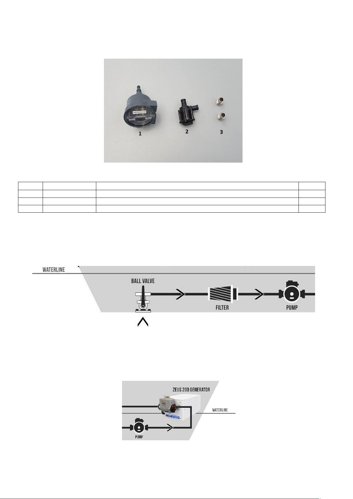
2.2 Filter and external pump.......................................................................................... 10
2.2.1 Components list ............................................................................................... 10
2.2.2 Mounting instruction ......................................................................................... 10
2.3 Exhaust gas line ..................................................................................................... 12
2.3.1 Components list ............................................................................................... 12
2.3.2 Mounting instruction ......................................................................................... 12
2.4 Fuel supply line ...................................................................................................... 13
2.4.1 Components list ............................................................................................... 13
2.4.2 Mounting instruction ......................................................................................... 13
2.5 Electrical system..................................................................................................... 15
2.5.1 Components list ............................................................................................... 15
2.5.2 Element identification ....................................................................................... 16
2.5.3 Electrical diagram............................................................................................. 17
2.5.4 Generator connections ...................................................................................... 18
2.5.5 External water pump connection, coolant sensor and provision for flow switch ......... 18
2.5.6 Display unit connections.................................................................................... 19
2.5.7 Temperature sensor connections ........................................................................ 19
2.5.8 Solar panel / Wind generator connections (optional) ............................................. 19
2.5.9 Secondary battery connections 12V/24V (optional)............................................... 20
2.5.10 Primary battery connections ........................................................................... 20
2.5.11 Connection of the D + / + 15 subkey .............................................................. 20
2.6 First start-up .......................................................................................................... 21
2.6.1 Loading of the cooling system............................................................................ 21
2.6.2 Loading of fuel system ...................................................................................... 21
2.6.3 Battery type selection ....................................................................................... 22
3 Installer Menu ............................................................................................................ 24
3.1 Menu activation ...................................................................................................... 24
3.2 Alarm pop-up reset ................................................................................................. 25
3.3 Historical of alarms ................................................................................................. 25
4 Fault or malfunctions.................................................................................................. 26
5 Technical data ............................................................................................................ 28
6 Warranty .................................................................................................................... 28
7 References ................................................................................................................. 28

Zeus200 Installation manual
V 1.0.7 - 12/10/2020 Page 3 of 28
1Introduction
Read these instructions carefully at least once before installing the generator.
ATTENTION
The system must only be installed by qualified personnel
To prevent hazards during assembly, operation and circulation, scrupulously observe the information
and instructions given in this manual.
The execution of the installation procedures and the correct connections are a fundamental
prerequisite for ensuring compliance with the corresponding regulations.
This is documented by the CE mark and the declaration of conformity given in chapter 1.2.
ATTENTION
Failure to follow the assembly instructions will result in the loss of
the product warranty by the manufacturer.
1.1 Security information
1.1.1 Destination of use (intended purpose)
The Zeus200 generator has been designed for electricity production; it is able to recharge the
batteries of campers and caravans during the static use of the vehicle. Any other type of use causes
the immediate loss of legal and / or commercial warranty.
The following situations entail the loss of warranty and liability claims by the manufacturer:
•Inappropriate assembly
•Use of fastening systems not listed in this manual may affect the mechanical safety of the
antenna system
•Unsuitable use
•Modifications or interventions on the components or accessories of the kit, which lead to the
reduction of mechanical and functional safety
•Inappropriate or forced opening of the kit components
•Failure to observe the assembly and safety operations described in this manual
NOTE
USAGE TEMPERATURES
To ensure the operation of the unit, the ambient temperature must be between -20oC and
+40oC. Activating the system outside these values may cause malfunctions or damages.
1.1.2 Safety and correct mounting
An essential safety factor is the proper execution of assembly operations, as well as electrical and
hydraulic connections. Scrupulously observe the conditions and assembly instruction supplied in this
manual. Modifications to the electrical system in the vehicle must be carried out only by qualified
personnel. Do not make changes to the generator on your own initiative.

Zeus200 Installation manual
V 1.0.7 - 12/10/2020 Page 4 of 28
1.1.3 General rules
1.1.3.1 Positioning of the display / control panel
•The control panel must be positioned/fixed in a clearly visible and protected position, at
the user's vision. It must not be placed in places subject to heat, dust or vibrations.
1.1.3.2 Generator placement
•Body parts and other vehicle components close to the Zeus200 generator must be
protected against excessive heat and possible contamination of fuel.
•The Zeus200 generator must not constitute a fire hazard, even in case of overheating.
This rule will be considered as satisfied by mounting the heater at enough distance from
all parts of the vehicle - ensuring adequate ventilation - and using fireproof materials or
thermal shieldings.
•The Zeus200 generator must not be placed in the passenger compartment; it can be
placed in a pre-arranged and well-ventilated locker. Do not install the device in a sealed
place or in a space in connection with vehicle interior.
•The User Manual must be supplied to the end user
•When assembling the Zeus200 generator, all necessary measures must be taken in order
to minimize the risk of personal injury or vehicle damage.
1.1.3.3 Fuel supply
•Zeus200 generator is designed to use the fuel present in the vehicle's tank. Check the
compatibility of the generator model purchased with the fuel in the vehicle tank.
•When using a separate fuel tank separate, the filler neck must not be placed in the
passenger compartment and must be fitted with a perfect closing cap to prevent leakage.
The filler neck must be clearly marked and must clearly identify the type of fuel used.
•A warning must be placed on the filler neck, indicating that the generator must be
switched off before refueling.
1.1.3.4 Fuel quality
•The Zeus200 generator works without problems with the engine diesel normally available
on the market. Maximum addition of bio-diesel available on the market according to DIN
EN 590. In the winter months diesel fuel is adapted for low temperatures, from 0°C to -
20°C. In case of extremely low external temperatures the generator - as well as in the
vehicle engine –could face some problems. See the provisions of the vehicle
manufacturer.
•In special cases and at external temperatures above 0°C the Zeus200 generator can work
with heating oil sec. DIN 51603 (from an additional tank). In case the Zeus200 generator
is powered from a separate tank, follow these steps:
•External temperatures above 0°C: diesel according to DIN EN 590 or heating oil
according to DIN 51603;
•External temperatures from 0°C to –20°C, use winter diesel according to DIN EN 590;
•External temperatures from –20°C to –40°C, user arctic diesel or polar diesel.
The addition of used oil is NOT allowed! After using winter diesel or diesel for low
temperatures, fill the fuel lines with standard diesel fuel and run the heater for 15
minutes. The Zeus200 generator is not approved to work with bio-diesel according to DIN
EN 14214.

Zeus200 Installation manual
V 1.0.7 - 12/10/2020 Page 5 of 28
1.1.3.5 Exhaust gas
•The exhaust gas outlet shall be placed in such a way to prevent exhaust gases from
entering the passenger compartment by means of ventilation devices, air vents or
windows. Position the through-hull for unloading on the side or on the stern of the hull so
that it remains above the waterline.
1.1.3.6 Combustion air inlet
•The air enters through the generator slots; the generator must be placed/protected in
order to avoid the slots be blocked by any object.
•The air for combustion of the generator must not be drawn in from the passengers
compartment.
1.1.3.7 General notes
•Use only PB / AGM / GEL and LiFeP04 batteries, selecting the correct charging
algorithm from the control unit.
•Recommended capacity: from 100 to 500Ah. Do not use in any circumstance old
batteries as they could cause the Zeus200 generator to malfunction.
•The manufacturer is not responsible for the battery status nor for an incorrect selection of
the type of recharge.
•It is not allowed to clean the generator with a pressure washer, using high pressure water
•The generator can not work if immersed in water or other liquids. In case of diving the
warranty will no longer be valid
•The warranty is valid only if the legal regulations, additional regulations and safety
regulations are complied with. Failure to comply with the law and safety regulations, as
well as repairs carried out by unauthorized personnel, even if with original spare parts,
relieves Mobil Tech Srl of any responsibility.
•The law is binding and also applies in countries where there are no specific rules.
•If the generator is not assembled by the vehicle manufacturer, but is subsequently
installed, these assembly instructions must be observed.
•If the generator is installed on ships not subject to vehicle registration regulations, the
assembly instructions and the applicable standards for the respective categories must be
observed.
•Other assembly requirements are indicated in the relevant paragraphs of this manual
1.1.3.8 Danger of injury, fire and intoxication
•Before starting any operation, disconnect the vehicle battery.
•Before carrying out any maintenance action, switch off the generator and allow all the hot
parts to cool down.
•It is not allowed to use the generator in closed places, e.g. garages, underground garages
or car park.
1.1.3.9 Safety rules for assembly and operation
•The Zeus200 generator can be assembled, verified and repaired only by the Mobil Tech
authorized personnel, in compliance with these assembly instructions or, if necessary, with
particular assembly instructions.
•Repairs carried out by third parties not authorized by the manufacturer and / or with non-
original spare parts can be dangerous and are therefore not permitted; they also
invalidate the approval of the generator.
•It is not allowed:
oTo make changes to the heating system
oTo use non-Mobil Tech spare parts

Zeus200 Installation manual
V 1.0.7 - 12/10/2020 Page 6 of 28
oDerogations, during assembly or use, of the values required by law, relevant for safety
and / or operation, reported in the mounting and user manuals. This applies in
particular to electrical wiring, fuel supply, positioning of the Zeus200 generator and
exhausted gas.
•For assembly and repair, original accessories and spare parts must be used.
•To operate the generator, only the control elements specified or permitted by us must be
used. The use of other control elements can lead to malfunctions.
•Faulty fuses must be replaced with fuses of the prescribed value.
•It is not alllowed to use the Zeus200 generator in the presence of highly flammable
materials in the area of the drain pipe or where flammable vapors or dusts may occur, for
example in the vicinity of:
ofuel depots
ocarbon depots
owood depots
ocereal or similar depots
•During refueling, the generator must be switched off.
•The generator installation compartment, when installed in a protective box or similar,
must not be occupied by other objects and must be absolutely clear. Above or near the
generator it is forbidden to store or transport flammable objects, fuel cans, oil cans,
sprays, gas cartridges, fire extinguishers, rags, garments, paper etc.
•In case of fuel loss from the generator fuel system (lack of seal), have the fault repaired
by an authorized workshop immediately.
•For topping up use only the antifreeze product indicated in the following pages. The
addition of a different type of antifreeze product can cause damage to the Zeus200
generator.
•The washing phase of the generator must not be interrupted (e.g. by operating the battery
disconnection), except for emergency cases.
1.1.3.10 Exemptions from safety and accident prevention requirements
•Any derogation from the safety requirements related to the assembly and operation of the
generator must be agreed with the manufacturer. As a general indication, the general
rules on accident prevention and company safety regulations must be observed.
1.2 Certifications and approvals
The Zeus200 generator comes with the following certifications:
EMC
EN61000-6-1:2007
EN61000-6-3:2007 + A1:2011
ENV (Cold A)
EN60068-2-1 (-15oC)
Acoustic test
EN ISO 3744
It has the following approvals:

Zeus200 Installation manual
V 1.0.7 - 12/10/2020 Page 7 of 28
1.3 Package contents
The package contains the following elements:
1. 1 generator
2. 1 power unit
3. 1 display unit
4. 1 external water pump
5. 1 water filter
6. 2 fittings from ¾ Inch to rod holder
7. 1 exhaust gas silencer
8. 1 thermo protective bandage with bands
9. 4 components envelopes (Generator, Discharge, Power, Electricity)
10. 1 trough hull
11. 1 drain pipe 24/28
12. 1 600mm dip tube
13. 1 fuel Rilsan pipe 2x4mm
14. 1 user manual
15. 1 installer manual
16. 1 fuel pump/generator cable
17. 1 external/pump/liquid level cable
18. 1 display cable
19. 1 2x6mm battery cable
1.4 Unpacking and preparations
Keep the original packaging; it will be used to avoid damages in case it’s necessary to send the
system for a repair. The manufacturer assumes no responsibility for transport damages.
Keep the packaging materials out of the reach of children.

Zeus200 Installation manual
V 1.0.7 - 12/10/2020 Page 8 of 28
2Mounting
2.1 Generator
2.1.1 Components list
#
Code
Description
N.
1
Z200BD12
Zeus200 generator
1 pc
Envelope #1:
#
Code
Description
N.
2
Z200-10-001
Inox generator bracket 50x150mm thickness 4mm
4 pcs
3
Z-01-011
Screw Hexagonal head M8x20mm A4
4 pcs
4
Z-01-025
Washer 9x24x2mm A4
4 pcs

Zeus200 Installation manual
V 1.0.7 - 12/10/2020 Page 9 of 28
2.1.2 Mounting instruction
1- The Zeus200 generator (1) must be positioned inside the hull, in a ventilated technical
compartment that is not communicating with the living area.
2- The Zeus200 generator must be positioned horizontally, with electrical connections, power
supply and discharge system downwards. Any other placement is not allowed.
3- In order not to create preloads to the cooling circuit, position the Zeus generator as close as
possible to the waterline. Bear in mind that heights of more than 1m are not allowed
between seacock/safety guillotine/filter/water pump and generator unit. When positioning,
keep in mind that the maximum length of the pipes dedicated to the cooling circuit must not
exceed 4 meters.
4- Leave adequate air circulation around the Zeus200 generator. Leave at least 10cm on every
side
5- Make sure that there are no objects inside the installation compartment that can move and hit
the Zeus200 generator.
6- To install the Zeus200 generator, use the 4 brackets (2), fixing them with screws (3) and
washers (4) or create a supporting structure suitable to support the weight.
7- Avoid positioning the generator on the floor, since any water inlets can damage it.
8- The Zeus200 generator must not be immersed in water or washed with a pressure washer
Installation notes
_______________________________________________________________________
_______________________________________________________________________
_______________________________________________________________________
_______________________________________________________________________
_______________________________________________________________________
_______________________________________________________________________
_______________________________________________________________________
_______________________________________________________________________
_______________________________________________________________________

Zeus200 Installation manual
V 1.0.7 - 12/10/2020 Page 10 of 28
2.2 Filter and external pump
2.2.1 Components list
#
Code
Description
N.
1
Z200-07-013
Water filter
1 pc
2
Z200-07-010
External cooling pump
1 pc
3
Z200-03-014
Hose connection from ¾ to 20mm
2 pcs
2.2.2 Mounting instruction
1. Starting from the seacock group with safety tap, which must be positioned below the
waterline, fit the supplied water filter (1). The filter must be positioned so that it can be
checked and, if necessary, cleaned or replaced
2. Immediately after the filter, place the supplied external water pump (2) in a vertical position
or possibly rotated 90° keeping the water inlet higher than the outlet following the correct
direction as indicated by the arrow printed on the pump itself. The external water pump must
not be submerged and must operate in the presence of water and not dry. Any damage to the
external water pump due to dry running is not covered by the warranty

Zeus200 Installation manual
V 1.0.7 - 12/10/2020 Page 11 of 28
3. Connect the external water pump to the exchanger of the Zeus200 generator using anti-
crushing spiral pipes not supplied and the fitting (3). Use the second fitting supplied (3) at the
outlet of the exchanger to connect a second pipe in order to allow the cooling water to flow
out of the hull through a sea discharge.
Note: the seacock must be located in a point that always remains below the waterline even if sailing
upwind. If a new sea cock is to be installed, a dynamic version is recommended. The sum of the
lengths of the spiral pipes must not exceed 4 meters. To lock the pipes use 2 steel clamps for each
fitting as per regulations. To block the fittings use specific sealant. The sea discharge must be
positioned 5/10cm above the waterline in order to avoid any smallest noise
Installation notes:
_______________________________________________________________________
_______________________________________________________________________
_______________________________________________________________________
_______________________________________________________________________
_______________________________________________________________________
_______________________________________________________________________
_______________________________________________________________________
_______________________________________________________________________
_______________________________________________________________________
_______________________________________________________________________
_______________________________________________________________________
_______________________________________________________________________
_______________________________________________________________________
_______________________________________________________________________

Zeus200 Installation manual
V 1.0.7 - 12/10/2020 Page 12 of 28
2.3 Exhaust gas line
2.3.1 Components list
#
Code
Description
N.
1
Z-05-009
Silencer
1 pc
2
Z-06-007
Discharge pipe 2mt
1 pc
4
Z200-09-008
Discharge through hull
1 pz
9
Z-04-007
Insulating bandage with clamps
1 pz
Envelope #3:
#
Code
Description
N.
3
Z-10-004
Exhaust silencer fixing bracket
1 pc
5
Z-02-008
Steel band 26-28 A4
4 pcs
6
Z-01-013
Screw hexagonal head M6X16 A4
1 pc
7
Z-01-027
Washer 6,6x18x2mm A4
1 pc
8
Z-01-034
Nut M6 A4
1 pz
2.3.2 Mounting instruction
1. The drain line must be directed towards the stern or the side of the boat. The exhaust line
must not pass under the generator as it may create overheating of the generator itself
2. Identify a point where to install the hull that is far from any possible contact with people. Pay
attention to install the silicone gasket supplied in order to avoid the contact of the hull pitch
with the resin of the hull
3. Connect the supplied steel tube (2) of 28mm L2mt. between the Zeus200 generator outlet (C)
and the exhaust silencer (1), as shown in the following diagram. The tube can be stretched up

Zeus200 Installation manual
V 1.0.7 - 12/10/2020 Page 13 of 28
to a maximum of 3m. In order to optimize the noiselessness of the drain, it is advisable not to
use pipes less than 1m long.
4. Fix the exhaust silencer in a stable way using the bracket (3) with screw (6), washer (7) and
nut (8), taking care that no part can interfere or be damaged due to the heat produced by the
drain.
5. Mount the exhaust terminal (4) to the through-hull taking care to perform a siphon in order to
avoid the sea water from coming into contact with the combustion chamber.
6. Secure the drain pipes with the 4 26x28x22mm steel clamps (5).
7. Finally, cover everything with the supplied thermal bandage or other thermally insulating
materials in order to avoid possible heat transfers inside the locker. Lock the thermal bandage
with the 4 clamps (9) provided.
Note: consider that the drain hose reaches temperatures above 200°C so make sure that it cannot
come into contact with anything. The thermal bandage must be handled with gloves and must be
immersed in water before use in order to simplify its installation.
2.4 Fuel supply line
2.4.1 Components list
#
Code
Description
N.
1
Z-06-008
Fuel Rilsan pipe 2x4mm
6 mt
Envelope #4:
#
Code
Description
N.
2
Z200-05-011
Suction pipe
1 pz
3
Z-02-003
Screw clamp 7-9 A4
6 pz
4
Z-05-005
Fuel pump
1 pz
5
Z-05-006
Fuel pump support
1 pz
6
Z-06-009
Fule hose for fitting 4x9mm length50mm
3 pz
7
Z-06-010
Fuel hose for fitting 4x9mm length 100mm
1 pz
8
Z-02-004
Screw clamp 8x10 A4
2 pz
2.4.2 Mounting instruction
1. Mount the 600mm dip tube provided (1) on the upper part of the tank or any predisposition of
the float / fuel pump. Drill with 18mm bit paying attention that the plastic shavings do not fall
inside the tank. Check that the height of the dip tube is correct. For no reason should it go
beyond 5cm from the bottom of the tank in order to leave in any case a sufficient quantity of

Zeus200 Installation manual
V 1.0.7 - 12/10/2020 Page 14 of 28
diesel fuel to guarantee the movement of the boat. Finally, block the dip tube, paying
attention to the presence of the sealing gasket.
2. It is possible to use other predispositions provided by the vehicle manufacturer.
3. It is not possible to interrupt the supply lines or the fuel return lines used for normal engine
operation
4. The maximum length of tube A between the tank and the dosing pump must be less than 1
meter.
Be very careful if existing draft lines are used as an inadequate passage of fuel
leads to malfunctions or a low performance of the Zeus200 generator.
5. The maximum length of the tube B between the pump and the Zeus200 generator must be 6
meters
6. Use the 2 clamps 8/10 only for the connection of the rubber fuel pipe on the dip tube and on
the generator, at the ends of the circuit. Use the 6 clamps 7/9 for the intermediate
connections between the fuel rubber hose and the rilsan hose.
7. Mount the fuel pump near the tank in longitudinal
position compared to the hull, 15/35° vertically
tilted so as to avoid the formation of air bubbles, in
such a way that the output will be higher than the
inlet. Inclinations less than 15° are not allowed,
while inclinations between 35° and 90° are tolerated.
If the pump is not tilted correctly the burner
performance can be negatively affected.
1 Allowed mounting position 35° –90°
2 Preferable mounting position 15° –35°
3 Not allowed mounting position 0° –15°
8. In the connections between the rigid fuel lines and the flexible fuel lines, the ends of the pipes
must be in contact, in order to avoid the formation of air bubbles
i.
1–correct connection 2- wrong connection (air bubbles)
9. The optional fuel filter should be inserted only when using fuel with a high percentage of
impurities
10. The fuel pump and the entire fuel supply line must be far from any heat source (exhaust
gases, engine, etc.)

Zeus200 Installation manual
V 1.0.7 - 12/10/2020 Page 15 of 28
2.5 Electrical system
2.5.1 Components list
#
Code
Description
N.
1
Z200-08-002
Power unit
1 pc
2
Z200-11-031
Cable for external pump 4x0.5mm
1 pc
3
Z1/2-08-003
Touch screen display 4,3”
1 pc
4
Z1/1-11-022
Display cable 7 mt
1 pc
5
Z1/2-11-023
Battery cable 2x6mm, l=1.5mt
1 pc
6
Z1/2-11-017
Cable for generator and fuel pump wiring L=6 mt
1 pc
Envelope #5:
#
Code
Description
N.
7
Z-02-009
Nylon cable tie 130x2.5mm
1 pc
8
Z-02-010
Nylon cable tie 200x4.8mm
10 pcs
Installation notes:
_______________________________________________________________________
_______________________________________________________________________
_______________________________________________________________________
_______________________________________________________________________

Zeus200 Installation manual
V 1.0.7 - 12/10/2020 Page 16 of 28
2.5.2 Element identification
The charging unit must be positioned as close as possible to the primary battery, in a dry place and
not subject to high temperatures. The wiring must be oriented downwards, in such a way that no
water can be in contact with electronic parts. The following figure shows the power unit and the
various elements required for installation.
The following picture shows the cable entries on the front side of the control unit; the table shows
the types of cables to be passed through each cable entry. In case of unused entrances, insert a plug
or a small piece of cable and then tighten the cable gland.
Element
Cable entry
Generator
1
Solar panel (opt.) –Neg
2
Solar panel (opt.) - Pos
3
Temperature sensor and
D+/15+ cable (signal key)
4
Engine battery (opt.)
5
Services battery
6
Display unit
7
Wiring terminals
Wiring
terminals
Dip switch
for battery
selection
Temperature
sensor
temperatura
Not
used
Not used
Not used
D+/+15
signal key

Zeus200 Installation manual
V 1.0.7 - 12/10/2020 Page 17 of 28
2.5.3 Electrical diagram
The following figure shows the wiring diagram, with the numbering of the terminals inside the control
unit and the number of cable entries to be used for the needed connections.
Terminal or
Connector
Element - Wire
Cable entry
1
Generator –Black wire 6mm
1
2
Generator –Red wire 6mm
1
3
Generator –Brown wire 4mm
1
4
Generator –Green wire 4mm
1
5
Sola panel (opt.) –Negative
2
6
Solar panel (opt.) –Positive
3
7
Engine battery (opt.) –Negative
5
8
Engine battery (opt.) –Positive
5
9
Services battery –Negative
6
10
Services battery –Positive
6
11
Display Unit –Yellow wire
7
12
Display Unit –Green wire
7
13
Display Unit –Brown wire
7
14
Display Unit –White wire
7
15
-
-
16
Generator –Black or cyan wire 0.5mm
1
17
Generator –Red or white wire 0.5mm
1
T
Temperature sensor
4
Key Signal
(center)
D+/+15 cable
4

Zeus200 Installation manual
V 1.0.7 - 12/10/2020 Page 18 of 28
2.5.4 Generator connections
Using the 6mt cable (6), perform the following operations:
1. Connect the 10pin connector to the generator
2. Pass the other end of the cable through the cable entry #1
3. Perform the following connections:
a. connect the 6mm black wire to clamp #1
b. connect the 6mm red wire to clamp #2
c. connect the 4mm brown wire to clamp #3
d. connect the 4mm green wire to clamp #4
e. connect the 0.5mm black or cyan wire to clamp #16
f. connect the 0.5mm red or white wire to clamp #17
g. the shielding braid of the data cable to clamps 16 and 17 must not be connected
4. Connect the fuel pump using the 6mt cable
The cables inserted in the round seats of the terminals must not
be tinned but must remain with the exposed copper. Eventually
use ferrules only for cables with a section of less than 2mm. To
be able to open the clamp spring, insert a slotted screwdriver in
the rectangular seat as shown and remove the screwdriver after
the cable has been positioned. Then check the perfect seal by
pulling the cable outwards
The following figure shows the connections to be made inside
the power unit
Only for Zeus200 24V (Model Z200BD24)
The red and black 6mm2wires coming from the generator
must not be connected to terminals 1 and 2 but to the cable
connector.
Black wire from the generator to the black of the cable
connector.
Red wire from the generator to the yellow of the cable
connector.
2.5.5 External water pump connection, coolant sensor and provision for flow
switch
Using the 2.5mt cable with 4-way connector (#2 pag. 15) and carry out the following operations:
1. Connect one end of the cable to the generator using the appropriate 4-way connector
2. Connect the two-way connector of the short cable to the cable coming from the exchanger
3. Connect the two-pin connector of the end of the 2.5m cable directly to the external water
pump, making sure that the connection is not immersed in the water.

Zeus200 Installation manual
V 1.0.7 - 12/10/2020 Page 19 of 28
4. Near the connector of the external water pump there are 2 wires connected together. They
are the predisposition for the connection of an optional on / off flow switch dedicated to
reading the presence of water. In the event of connection in the event of a water shortage
from the seacock, the Zeus200 generator will stop before switching on and the display will
indicate the error.
2.5.6 Display unit connections
Using the white cable (4), perform the following operations:
1. Connect the cable to the display, using the appropriate
connector
2. Pass the other end of the cable through the cable entry #7
3. Perform the following connections in the control unit:
a. Connect the yellow wire to clamp #11
b. Connect the green wire to clamp #12
c. Connect the brown wire to clamp #13
d. Connect the white wire to clamp #14
The figure shows the connections to be made inside the control unit
2.5.7 Temperature sensor connections
Using the appropriate cable (#1 pag 15), perform the
following operations:
1. Place the sensor in the battery compartment
but not on the battery, securing it using the
special adhesive
2. Pass the other end of the cable through the
cable entry #4
3. Connect the end of the cable to the T connector
The figure shows the connections to be made inside
the control unit
2.5.8 Solar panel / Wind generator connections (optional)
The solar panel output cable must be connected to the control unit as follows:
1- The negative must be passed through the cable entry #2 and connected to the clamp #5
2- The positive must have passed through the cable entry #3 and connected to the terminal #6
The system is able to manage solar panels or ind generators capable of delivering up to a
maximum of 80V/300W. The source must be connected directly without interposing any other
control unit. The instantaneous charge current and the history of the last 48 hours will be shown on
the display as specified in the user manual.
Note: if the batteries to be recharged have voltages of 24V, use 72-cell photovoltaic panels or wind
generators with working voltages higher than 36V.

Zeus200 Installation manual
V 1.0.7 - 12/10/2020 Page 20 of 28
2.5.9 Secondary battery connections 12V/24V (optional)
The Zeus200 generator charges either secondary batteries or both 12V and 24V motors. The cable to
the secondary battery (motor) must pass through the cable gland 5. For 12V batteries the section to
be used to avoid voltage drops is shown in the following table:
Length
Section
Up to 3mt
6 mm2
From 3 to 5 mt
8 mm2
From 5 to 7.5 mt
12 mm2
From 7.5 to 10 mt
16 mm2
In case of connection to 24V secondary batteries it is possible to halve the section.
When cables with sections over 6mm2 are used, the use of crimping tips is allowed in order to
reduce the section of the cable diameter and allow it to be inserted in the terminal on the control unit
The cable must be connected as follows:
1. The negative wire must be connected to clamp #7
2. The positive wire must be connected to clamp #8
3. Insert a 30A fuse (15A in case of 24V) near the engine battery
Note: For battery selection follow carefully the instruction given in chapter "First start-up”
2.5.10 Primary battery connections
12V –model Z200BD12
24V –model Z200BD24
Using the appropriate cable (#5 at pag 15), perform
the following operations:
1. Pass the cable through the cable entry #6
2. Connect the negative to clamp #9
3. Connect the positive to clamp #10
4. Even if the power unit has dedicated fuses,
insert a 25A fuse for the battery with 12V
voltage or 15A with 24V voltage near the
service battery to protect the cable
The figure shows the connections to be made inside
the control unit
At this point the system turns on and the "Home"
screen will appear on the display.
Before switching on the system follow the
instructions given in chapter "First start-up”
2.5.11 Connection of the D + / + 15 signal key
Connect the D + cable or the +15 subkey to the "Key Signal" terminal of the power unit as shown on
the connections figure (pag. 17), passing it inside the cable gland 4 which already houses the cable
dedicated to the temperature sensor. The connection is mandatory as it deactivates the operation of
the Zeus200 generator if the engine is running.
This manual suits for next models
1
Table of contents
Popular Inverter manuals by other brands

Bergey
Bergey POWERSYNC II Series Operator's manual & installation instructions

Sungrow
Sungrow SG25CX-SA user manual

Sumitomo Drive Technologies
Sumitomo Drive Technologies SI-485/J-H Technical manual

Techno Sun
Techno Sun OFF1307 user manual

enphase
enphase IQ8D-72-E-US Design guide

Huawei
Huawei SUN2000 M0 Series user manual