SECTION 1 – M unt P tenti meters, Terminal Strips and F tswitch
Please refer t DRAWING 1 and DRAWING 2.
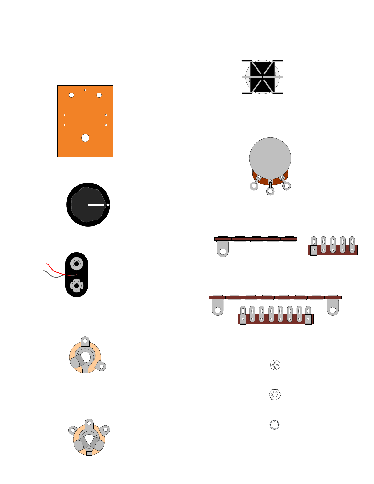
Orient the box with ½” hole nearest you.
Mount the 1ML potentiometer in the 5/16" hole on the top right side of the box. Orient this pot so
that lug “1” is pointing down toward the bottom of the box. Fasten the nut and tighten.
Mount the 250KL pot in the 5/16" hole on the top left side of the box. Make sure that all three
lugs are facing down toward the bottom of the box. Fasten the nut and tighten.
Using the hardware provided, mount the terminal strips as
shown in D AWING 2. The lock washers go underneath
each respective hex nut for a tight grip.
6
Mount the footswitch in the ½” hole as shown in D AWING 2 using hardware provided. The
large nylon washer goes under mounting nut on the outside of the box. The lock washer mounts
on the inside between the box surface and the other nut. Make sure the footswitch solder lugs
are oriented as shown in the drawing.
Bend back and remove the alignment tab on the top of each potentiometer
using a pair of pliers before mounting the pots so that they can mount flush
against the enclosure surface.
Terminal Strip
M unting
Bracket
utside b x
inside b x
Alignment
Tab
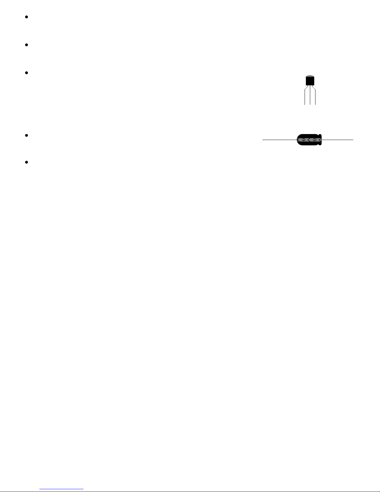
SECTION 2 – M unt Input & Output Capacit rs, ¼” Jacks and Wire the F tswitch
Connect one of the 0.1µF capacitors from Lug “1” of the footswitch to Terminal #2 as shown in
D AWING 3.
Please note that each terminal has been numbered as illustrated in
DRAWING 2 and will be referred to as a “Terminal #_” when
connecting different components and wires throughout the assembl
instructions.
Connect another 0.1µF capacitor from Lug “4” of the footswitch to Terminal #6 as shown.
Unless noted otherwise, “connect” means to trim the component’s leads to a reasonable length, wrap them tightl
around their connection points and solder. (See “Soldering Tips” on page 5).
Onl solder the connection at Lug “4” at this point. (There will be three more components connected to Terminal #6).
Mount the input jack in the 3/8" hole on the left side of the box. The washer goes under the nut
on the outside of the box. Make sure to center the “ground” lug of the input jack so that it is
facing up towards the enclosure opening. This will make soldering the connections easier.
Please refer t DRAWING 3.
You might find it easier to mount the capacitors upside-down with the insulated top end of each cap touching the
enclosure surface.
Connect one of the 1M resistors from Lug “1” of the footswitch to Terminal #1.
Connect the other 1M resistors from Lug “4” of the footswitch to Terminal #8.