SECTION 1 – Mount Large Components
Stripping wire, tinning wire and soldering. Throughout these instructions you will be told to strip
and tin a length of wire numerous times. Unless noted otherwise, cut the wire to the length stated in
the instructions. Then strip ¼” of insulation off each end. Twist each end of the stranded wire, and
apply a small amount of solder to each end (i.e. tin the wire ends).
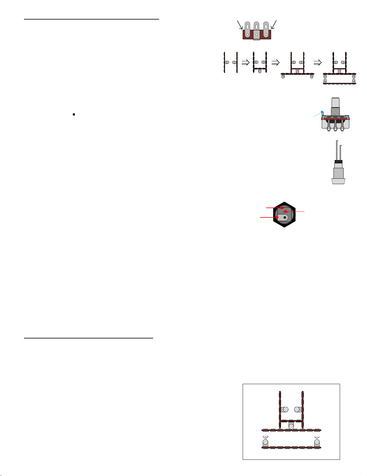
Please refer to DRAWING 1 and DRAWING 2.
Orient the enclosure with the two 5/16" holes on top.
Using the seven screws, nuts and lock washers provided,
fasten the five terminal strips to match DRAWING 2.
12
3
4 5 6 7
The ends may require trimming or filing for a perfect fit. Fasten the two 5 lug
terminal strips and the 3 lug terminal strips first. Then fasten the two 8 lug terminal strips.
Alignment
Tab
Mount the DC power jack in the 15/32" hole on the left side of
the enclosure. Orient its solder lugs so that the center-pin lug
is facing the bottom side of the enclosure. CENTER-PIN
LUG
POSITIVE-SWITCH
LUG
POSITIVE
LUG
Mount the input jack in the 3/8" hole on the left side of the enclosure with the hardware provided.
The washer goes under the nut on the outside of the enclosure. Make sure the center solder lug of
the input jack is facing up. Correct positioning of the jack makes soldering the connections easier.
Mount the output jack in the 3/8" hole on the right side of the enclosure. Make sure the two solder
lugs are in their most upright position before tightening the nut.
Mount the footswitch in the 15/32" hole in the center of the enclosure. The black washer goes under
the mounting nut on the outside of the enclosure. Then the lock washer mounts on the inside
between the enclosure surface and the other nut. Discard the nylon washer. Make sure that the
footswitch is oriented to match DRAWING 2.
SECTION 2 – Wire Large Components
Please refer to DRAWING 3.
Please note that each terminal has been numbered as
illustrated here and will be referred to as a “terminal #_” when
connecting different components and wires throughout the
assembly instructions.
7
12345678
9101112131415
16
17
18
19 20
21
22
NC
NC
NC
NC
232425
This will prevent the stranded wire from fraying and will make the
final soldering much easier.
Apply the sticker to the top of the box then use a blade to cut out the holes. See pg 13 for guide.
Mount the SPDT toggle switch in the ¼” hole at the top. Leave all stock hardware on the bushing
and make sure they are fully threaded before inserting through the chassis hole. Use the black
dress nut to mount the switch. Align the switch as shown in the drawing and tighten the nut.
Mount the LED in the ¼” hole above the footswitch’s mounting hole. The lock washer goes under
the nut inside the enclosure. Align the LED leads so that the cathode (short lead) is closer to the
footswitch as shown in Drawing 2.
anode
Mount the 1KL pot in the 5/16" hole on the left and the 500KA pot in the remaining 5/16" hole
on the right. Bend back and remove the alignment tab on the top of each potentiometer
using a pair of pliers before mounting the pots so that they can mount flush
against the enclosure surface.
end end
cathode


 User manual")