manuals.online logo
Brands
  1. Home
  2. •
  3. Brands
  4. •
  5. Model Rockets
  6. •
  7. Toy
  8. •
  9. Model Rockets SuperTooboh User manual

Model Rockets SuperTooboh User manual

Assembly
Instructions
Parts Included:
1 Nose Cone
1 Lower Body Tube
1 Payload Tube
6 Fin Tubes
1 Thrust Ring
2 Centering Rings
1 Motor Spa er Tube (White)
1 Motor Hook
2 Laun h Lugs
1 Coupler
2 Bulkheads
1 S rew Eye
1 Kevlar Sho k Cord (yellow)
1 Elasti Sho k Cord (white)
1 Para hute kit
1 De al Sheet
Materials Not Included:
Pen il
Yellow Wood or White Glue
Masking Tape
Motor Mount and
Shock Cord Assembly
Step 1 –
Tie a single knot at the end of the
yellow kevlar sho k ord.
Step 2 –
Insert the flat end of the metal
motor hook into the pre- ut slot ¼” from the
end of the motor tube.
Step 3 –
Slightly expand the inside of the 2
larger entering rings by twisting on the end
of the nose one. Important: Don’t expand
the smaller trust ring.
Step 4 –
While holding the motor hook in
the slot, apply glue around the motor tube
between the marks. Push the expanded end
of the entering rings over the motor hook
with the knotted end of the kevlar sho k ord
through the rear entering ring until the rings
are between the marks on the motor tube.
Step 5 –
Apply glue around the outside of
the thrust ring and insert into the motor tube
at the end where the motor hook is inserted.
Push in until against the motor hook and flush
with the end of the motor tube.
Step 6 –
Loop the yellow kevlar sho k ord
through the thrust ring end of the motor tube.
The rings should be positioned as shown.
2
Inserting and Attaching
the Motor Mount
Step 1 –
Refer to the drawing below to
lo ate the bottom of the stage tube by the
1 1/8” fin slot distan e. Using a Q-tip or your
little finger apply glue liberally around the
inside end of the lower body tube ½” in at the
end of the slotted for the fins.
Important: Do the following motor mount
insertion in one move. Do not stop until the
motor mount is in the orre t position.
Step 2 –Insert the motor mount and push
in until the bottom of the motor tube is flush
with the bottom on the lower body tube. Set
aside to dry.
Attaching the
Launch Lug
and Fins
Step 1 –
Apply a thin line of glue to the
laun h lug and atta h where marked on the
lower body tube and set aside to dry for a few
minutes.
Step 2 –
Apply a thin line of glue to the
outside of one of the fin tubes along the
length. Atta h 2 fin tubes together and set
aside to dry for a few minutes on a flat
surfa e to keep them aligned parallel to ea h
other. Do this for 3 pairs of fin tubes.
Step 3 –
Apply glue in a thin line along the
length of the first fin tube pair in 2 pla es and
the laun h lug. Refer to the fin tube layout
guide on this page for glue lo ations between
the lower body tube, fin tubes, and the laun h
lug. Atta h the first fin tube pair to lower body
tube and laun h lug while aligning with the
line around the tube as shown.
3
Step 4 –
Apply glue in a thin line along the
length of the se ond fin tube pair in 3 pla es.
Refer to the fin tube layout guide on this page
for glue lo ations between the lower body
tube and the fin tubes. Atta h se ond fin tube
pair to the lower body tube and first fin tube
pair while aligning with the line around the
tube as shown.
Step 5 –
Apply glue in a thin line along the
length of the last fin tube pair in 2 pla es and
the laun h lug. Refer to the fin tube layout
guide on this page for glue lo ations between
the lower body tube, fin tubes, and the laun h
lug. Atta h the last fin tube pair to the body
tube, se ond tube pair, and laun h lug while
aligning with the line around the tube as
shown. Set aside the whole assembly to dry
for a few minutes.
Assembling the
Payload Section
Step 1 –
Apply glue to the hole in the
enter of the plywood bulkhead. S rew in the
s rew eye in the same hole. Apply glue to the
edge of the bulkhead and insert into the
oupler until flush with the end of the oupler.
Set aside to dry.
Step 2 –
Apply a thin bead of glue around
the inside edge of the payload tube and insert
the bulkhead assembly until it is ½” from the
end of the payload tube.
Step 3 – Apply a thin bead of glue along
the length of the laun h lug and atta h to the
body tube where the laun h lug line is
marked. Allow to. After it is dry, fillet the
laun h lug on the payload se tion.
Step 4 –
Che k the fit of the oupler in the
body tube. If ne essary, sand with #240 grit
sandpaper (usually not ne essary) for a
fri tion fit. Wrap masking tape around the
shoulder of the nose one for a snug fit in the
payload tube.
Attaching the Parachute
and Payload Section
Step 1 –
Feed the yellow kevlar sho k ord
through the bottom of the lower body tube
and pull out through the top.
Step 2 –
Tie both the white elasti sho k
ord and the yellow kevlar sho k ord
together with a single looping knot and pull
both sho k ords apart to tighten the knot.
Step 3 –
Tie the nose one to the end of
the white elasti sho k ord.
Step 4 –
Remove the para hute parts from
the bag ontaining the para hute and follow
the para hute assembly instru tions printed
on the para hute sheet.
Step 5 –
Tie the end of the para hute
shroud lines to the s rew eye on the payload
se tion.
4
Finishing Your Rocket
(O tional)
Step 1 - Sand the nose one with #240 grit
sandpaper to allow paint to sti k.
Step 2 –
Roll up a sheet of paper and insert
into the bottom of the ro ket body tube to
hold your ro ket, apply a thin oat of flat
white or gray primer spray enamel to the
whole ro ket using even ba k and forth
movements. Let the primer dry and sand
using #240 grit sandpaper. Re- oat and sand
as ne essary.
Step 3 –
Apply a first thin olor oat of
gloss spray enamel to the whole ro ket using
even ba k and forth movements. Let the first
oat ta k up for a few minutes. Then follow up
with a heavier oat. Do not oat too heavily or
the paint will sag. The best results are
obtained when the olor oat is just thi k
enough to gloss. If additional oats are
needed to over the primer with full olor, re-
apply after the olor oat has ta ked up within
the first hour or wait 24 hours until the olor
oat is ompletely dry. Let the final oat dry
for 24 hours.
Step 4 –
Remove the pressure sensitive
de als from the ba king paper and apply to
the fins and body tube. Use the pi ture on the
over of this manual for a guide to de al
pla ement.
Flying Your Rocket
Flight checklist:
□
Model Ro ket
□
Laun h Pad & Controller w/Batteries
□
Re overy Wadding
□
Model Ro ket Motors and Igniters
Re ommended Motors for the Toob’oh ro ket
are A8-3, A6-4, B4-4, B6-4, C6-3 & C6-5
Step 1 –
Insert 2 rumpled re overy
wadding sheets into the body tube and the
folded sho k ord after the re overy wadding.
Step 2 –
Fold the para hute and roll up
small enough to fit into the ro ket body tube
and insert into the ro ket body tube, then
insert the payload se tion into the body tube
to omplete the re overy assembly.
Step 3 –
Install model ro ket motor igniter
a ording manufa turers re ommended
pro edure.
Step 4 –
Insert the ro ket motor with the
nozzle/igniter end fa ing the rear of the
ro ket. The motor should lip into pla e with
the motor hook retaining the motor. If the
ro ket motor is too tight, you an remove a
thin layer of the paper or the motor label.
IMPORTANT:
FOLLOW THE N.A.R.
SAFETY CODE REGARDING
LAUNCHING AND THE USE OF MODEL
ROCKET MOTORS

Other Model Rockets Toy manuals

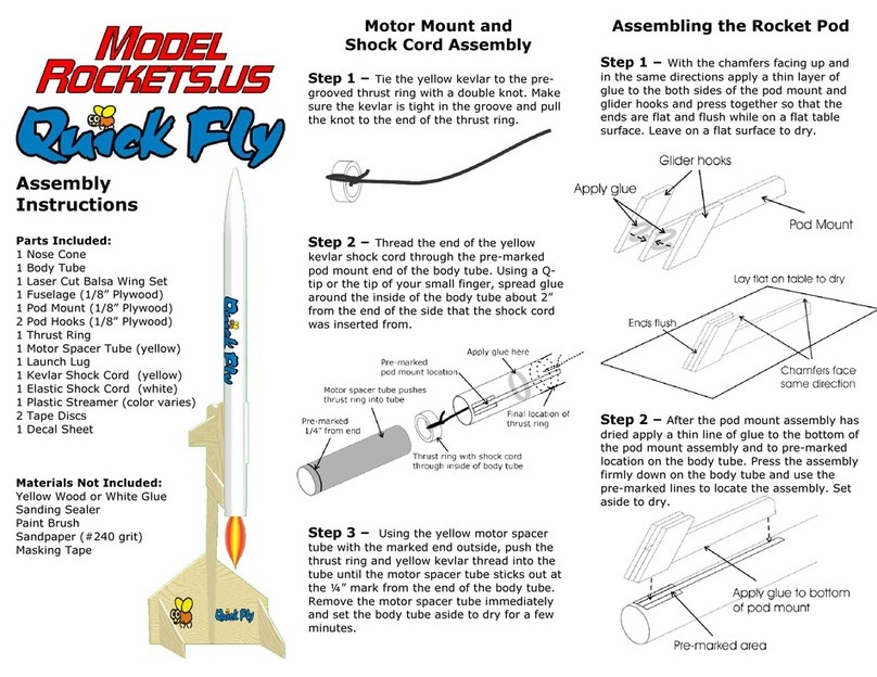
Model Rockets Ruick Fly User manual

Model Rockets

Model Rockets Ruick Fly User manual

Model Rockets 2.6 Rim-24 Tartar Expert Series User manual

Model Rockets

Model Rockets 2.6 Rim-24 Tartar Expert Series User manual

Model Rockets Turbo User manual

Model Rockets

Model Rockets Turbo User manual

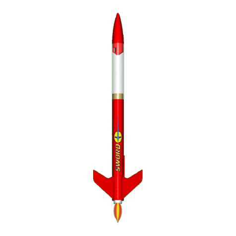
Model Rockets SWORD User manual

Model Rockets

Model Rockets SWORD User manual

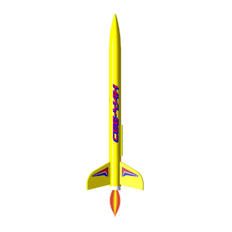
Model Rockets CEE-YAH User manual

Model Rockets

Model Rockets CEE-YAH User manual

Model Rockets Super CENTAURI User manual

Model Rockets

Model Rockets Super CENTAURI User manual

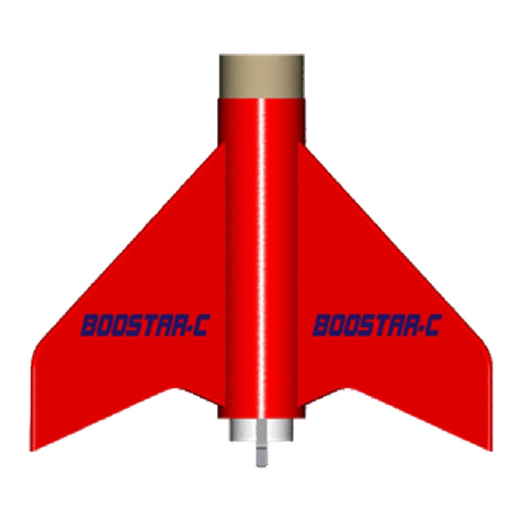
Model Rockets BOOSTAR-C User manual

Model Rockets

Model Rockets BOOSTAR-C User manual

Popular Toy manuals by other brands

Fisher-Price imaginext DC Super Friends HNW08 manual

Fisher-Price

Fisher-Price imaginext DC Super Friends HNW08 manual

PARKZONE Conscendo Advance instruction manual

PARKZONE

PARKZONE Conscendo Advance instruction manual

Eduard Bf 109E-4 quick start guide

Eduard

Eduard Bf 109E-4 quick start guide

Faller 140315 manual

Faller

Faller 140315 manual

H-KING FRENZY instruction manual

H-KING

H-KING FRENZY instruction manual

Multiplex EXTRA 330SC Indoor Edition Building instructions

Multiplex

Multiplex EXTRA 330SC Indoor Edition Building instructions

Fisher-Price Power Wheels My First Craftsman K5314 Owner's manual and assembly instructions

Fisher-Price

Fisher-Price Power Wheels My First Craftsman K5314 Owner's manual and assembly instructions

REVELL Sail Training Ship Alexander Von Humbolt Assembly manual

REVELL

REVELL Sail Training Ship Alexander Von Humbolt Assembly manual

Mattel HotWheels ROBO-LIFT SPEED SHOP instructions

Mattel

Mattel HotWheels ROBO-LIFT SPEED SHOP instructions

Hasbro Playskool Heroes Transformers Rescue Bots... quick start guide

Hasbro

Hasbro Playskool Heroes Transformers Rescue Bots... quick start guide

Kogan KA2PLAZTAGA quick start guide

Kogan

Kogan KA2PLAZTAGA quick start guide

Mattel Disney TOY STORY STAR COMMAND SPACESHIP... instructions

Mattel

Mattel Disney TOY STORY STAR COMMAND SPACESHIP... instructions

erc PIPER J-5 manual

erc

erc PIPER J-5 manual

Mattel my PASSWORD JOURNAL instruction manual

Mattel

Mattel my PASSWORD JOURNAL instruction manual

LGB 22620 instruction manual

LGB

LGB 22620 instruction manual

Carrera RC 370200996 Assembly and operating instructions

Carrera RC

Carrera RC 370200996 Assembly and operating instructions

Pro Boat Blackjack 26 instruction manual

Pro Boat

Pro Boat Blackjack 26 instruction manual

AquaCraft WildCat EP manual

AquaCraft

AquaCraft WildCat EP manual

manuals.online logo
manuals.online logoBrands
  • About & Mission
  • Contact us
  • Privacy Policy
  • Terms and Conditions

Copyright 2025 Manuals.Online. All Rights Reserved.