manuals.online logo
Brands
  1. Home
  2. •
  3. Brands
  4. •
  5. Modern Fan Co
  6. •
  7. Fan
  8. •
  9. Modern Fan Co Ball User manual

Modern Fan Co Ball User manual

A note about our online installation instructions:
Most Modern Fan Co. products have been in our assortment for several years
or longer. As we continually work to improve product performance and user
experience, we occasionally introduce subtle (and sometimes dynamic)
product changes. These can affect the steps associated with assembly and
installation of our products depending on when a fan was produced.
709 Washington Street • Ashland, OR 97520 • (tel) 888.588.3267 • (e) [email protected]
w w w . m o d e r n f a n . c o m
The instructions posted here are intended to represent our most current product versions and
configurations and the associated installation steps. If your fan or parts of your fan do not appear to
match what is included here, please contact customer service for guidance and support in
identifying which version of a fan you may have and provision of the associated installation
instructions which correspond to that version.
If in doubt, or if you have any questions at all related to assembly, installation or operation of your
fan, please contact us!
THE MODERN FAN COMPANY
Customer Service
M-F 8am - 4pm (PST)
(ph) 888.588.3267
www.modernfan.com
(1) Remove and identify contents of carton.
Ball Fan- Installation instructions
Should you have any questions or difficulty installing your new fan,
please contact Modern Fan Co. customer service immediately.
Note: Power supply must be turned off prior to any contact with electrical wires. It is
recommended that a licensed electrician be hired to install your ceiling fan.
Ball
optional control
balancing kit
hanging bracket
blades
canopy
hardware
package
fan body
down rods
half ball
(2) Remove bottom dome by rotating counterclockwise.
You may need to hold the upper portion of the fan body
with one hand as you are removing (unthreading) the
bottom dome with the opposite hand. With bottom dome
removed, place fan body on either piece of packing foam,
with wire bundle facing down and bottom of fan facing up.
(3) Carefully insert blades into rotor slots, and using screws
from hardware package, secure blades to rotor. The
counter sink screws (“blade center screws”) are for the single
blade hole outside the rotor and the pan head screws
(“blade holder screws”) are for the two holes inside the rotor
area for each blade.
(4) If your fan was ordered/configured with a light, identify all parts as shown here
and follow steps (a) through (e). Otherwise, proceed to step (5).
(a) Remove switch housing by unscrewing and
removing three screws as shown here. Set
the screws aside for reinstallation at step (c).
(b) Depending on when your fan was
produced, a 2-pin terminal may already be
present. If so, skip to step (c). If your fan has
separate wire connectors, join the bridge
connector ends with light kit lead wires from
fan.
(c) Route 2-pin terminal through center hole
of lighting plate and secure with screws from
step (a). Be sure that all wires are inside the
outer edges of the switch housing.
Lighting plate
LED Cover
LED Board
Glass diffuser
Bridge connector
Light kit hardware
pack(s)
(d) Position and insert 2-pin connector into
block near center hole of LED board. Position
LED board flat on lighting plate so that three
cutouts are positioned over attachment holes.
Feed any excess wire back into area behind
lighting plate.
(e) Position LED cover over LED board so
that attachment holes are aligned with
cutouts and holes in adapter plate. Using
three additional, small pan head screws
included with hardware pack, secure LED
cover and LED board to adapter plate.
Note: You may store the switch housing from step (a) and the bottom dome from
step (2) for re-use in the future should you ever decide to remove your light kit.
(5) Using the existing screws from your junction box, or the
machine screws from the hardware package, secure the
hanging bracket to the ceiling junction box.
(6) Remove the stopper screw and loosen the set screw on
the fan collar. Set the stopper screw aside for step (8).
(7) Remove stopper pin and half ball from small down rod
by loosening set screw on half ball. Set all parts aside for
step (10).
(8) Run fan wires through selected down rod. Reinstall
stopper screw from step (6) and firmly tighten set screw on
fan collar against down rod.
Note: If ceiling height allows, using a longer down rod will
increase airflow and efficiency.
(10) Reinstall half ball on end of down rod. Be sure that
stopper pin is inserted through down rod and seated in half
ball. Tighten set screw against down rod.
(9) Slide fan canopy over down rod and carefully rest on
top of fan body.
set screw
stopper screw
stopper pin
set screw
(11) Lift fan to ceiling and set half ball in the hanging
bracket so that the ridge on the edge of the hanging
bracket is seated in the slotted channel in the half ball.
With fan safely suspended by bracket, make wire connections with wire nuts included
in hardware package as described in the control installation instructions. If using the
optional #003, #004 or #005 control, the receiving unit should be placed inside the
arms of the hanging bracket and connected now.
channel and ridge
(12) Remove set screws on the sides of the hanging
bracket. Lift canopy to ceiling. With slots on side of canopy
aligned with set screw holes on hanging bracket, reinstall
and tighten set screws to hold canopy in place.
(13) Your fan is reversible for summer and winter operation.
The reverse switch is located just inside the labeled opening
on the upper motor housing. The LEFT position is for
summer and the RIGHT position is for winter. Because the
switch is recessed, it will be necessary to use the end of a
pencil or screwdriver to carefully move the switch.
(14) Reinstall bottom dome or glass diffuser if your fan has
a light kit. Rotate in the clockwise direction until dome or
diffuser comes to a stop.
(16) The rotor and motor of your fan have been dynamically balanced at the factory.
In addition, the blades have been matched to the nearest gram to ensure a well
balanced ceiling fan. Furthermore, a blade balancing kit has been included with your
fan. Please refer to the instructions packaged with the balancing kit should your fan
require additional balancing.
(15) Install wall control as described in the control installation instructions (unless you
are using a handheld remote control only).
709 Washington Street • Ashland, OR 97520 • (tel) 888.588.3267 • (e) [email protected]
w w w . m o d e r n f a n . c o m
Modern Fan Co. Control Options
for AC motors and LED light kits
When ordering your fan, you should have selected the control most
appropriate for your fan and electrical requirements.
Controls are intended for use with one fan (except #009A/009B as noted).
A basic fan control used to operate a fan only, providing four
speeds. *Not compatible with remote control
For operation of a fan with light. Requires two
circuits (three wires). Provides four speeds and full
range dimming. *Not compatible with remote control
Designed for independent operation of a fan and light using
only one circuit (two wires). Provides three speeds and full
range dimming or “on/off” switching and wires into wall box.
Includes wall switch, switch plate and receiver.
Designed for independent operation of a fan and light using
only one circuit (two wires). Provides three speeds and full
range dimming or “on/off” switching. Includes handset,
receiver, two AAA batteries and comes with a wall hanging
bracket for handset.
A combination control set providing three speeds and full
range dimming or “on/off” switching from wall control and/or
remote handset. Includes one receiver, a remote handset with
hanging bracket, two AAA batteries and wall control with
switch plate.
#FC-001 Fan Speed Control
#FC-002 Three Wire Fan Speed & Light Control
#FC-003-LED Handheld Remote Control
#FC-004-LED Two Wire Fan Speed & Light Control
#FC-005-LED Two Wire Wall Control with Remote Handset
A three speed fan control designed to control two fans
(#009A) or three to five fans (#009B) on a single circuit.
Separate control/switching of lights must be planned if this
control is to be used for fans with lights. For AC motors only.
*Not compatible with remote control
#FC-009A/009B Multi-Fan Control (sold separately from fans)
Installation Instructions: With power turned off at breaker, make wire
connections from the fan to the power supply at the ceiling and from the
control to power at wall box as shown in the wiring diagrams below.
Note: For #009A or #009B, refer to printed instructions included in control
box/packaging.
Fan
Cap off BLUE wire
(unused load for light)
BLACK motor
WHITE neutral
AC in Load
AC in Neutral
AC in
Fan
BLUE (light)
BLACK
to motor
WHITE (neutral motor)
AC in Neutral
AC in
BLACK/White
AC in load
BLACK (motor)
BLUE
to light
GREEN- connect ground
wire to grounded
hanging bracket or
mounting plate
GREEN-
connect
ground wire
to grounded
hanging
bracket or
mounting
plate
GREEN
Ground
GREEN
Ground
#001 Wiring Diagram
#002 / #002ND Wiring Diagram
On/Off Switch (w/ #003) or
Wall Switch (w/ #004/#005 )
Fan
BLUE
BLACK
WHITE
AC in
Neutral
AC in
AC in
Load
GREEN-
connect
ground wire
to grounded
hanging
bracket or
mounting
plate
Green
Ground
#003 / #004 / #005 Wiring Diagram
Receiving
Unit
Load
WHITE
BLACK
Cap off ORANGE*
wire if present
(unused neutral for light)
ORANGE (neutral light)
BLACK (motor)
WHITE (neutral motor)
BLUE (light)
BLACK
to motor
RU
ORANGE
Antenna
WHITE
BLACK
BLUE
To Black (motor load)
WHITE
BLACK
to A/C Power In (Neutral)
#003, #004 and #005 Receiving Unit Wiring Instructions:
With fan suspended from ceiling and with power off at breaker box, make
wire connections as shown below. The receiving unit sits in the ball hanging
bracket of most models as pictured (a), or in the upper portion of the fan
body in flush mount models (b).
(a)
(b)
Receiving Unit Placement:
While there is ample room for the receiving unit as shown here, the wires
can sometimes become difficult to manage in the space available. Trimming
excess wire before making connections can ease wire management.
Tip: Splicing lighter gauge wire to the power supply and positioning the
heavier wires up into the junction box can also ease wire management.
to A/C Power In (Load)
To White (motor neutral)
To Blue (light load)
ORANGE
To Orange (light neutral)
The remote handset (#003/#005) and wall control (#004/#005) ship pre-set
for “on/off” operation of the light. The LIGHT button will turn the light on
and off when pressed and released.
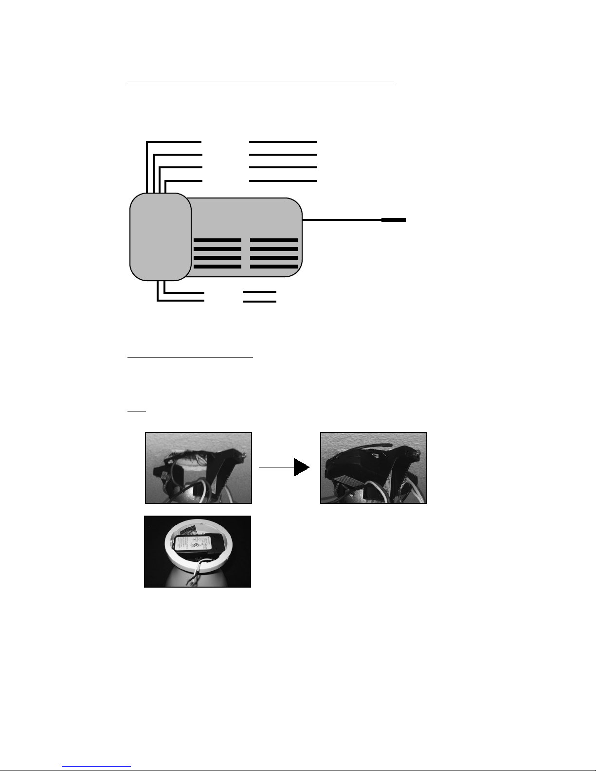
To enable dimming function on the remote handset, move the vertically
oriented dip switch down from ON to 1 (or from X to D). On the wall control,
move the right (or lower) dip switch from ON to 2 (or from X to D). Dip
switches are located inside the battery cover of the remote handset and on
the left side of the wall control. See image below.
With dimming enabled, pressing and holding the LIGHT button will increase
or decrease brightness, stopping at the minimum and maximum brightness
levels or when the LIGHT button is released.
Dimming Selector Switch (for #003, #004 and #005 only):
Dip switches:
Universal or Individual RF Channels (for #003, #004 and #005 only)
The remote handset (#003/#005) and wall control (#004/#005) ship pre-set
to a “Universal” or common RF channel. If you have multiple fans in close
proximity, you will want to set the remote handset and/or wall control to an
“Individual” (or unique) channel. To select the “Individual” channel on the
remote handset, move the horizontally oriented dip switch from ON to 1 (or
from U to I). On the wall control, move the left (or upper) dip switch from ON
to 1 (or from U to I). See images above.
After selecting the individual RF channel(s), you will need to pair your
remote handset and/or wall control with the receiver. Begin by turning
power off on the wall control, on the main switch leg or at the circuit breaker
if there is no wall control or on/off switch in use. Switch the power supply
back on and immediately press and firmly hold down the LIGHT and FAN
OFF buttons simultaneously for 10 seconds. If using both a remote
handset and wall control with a fan, repeat these pairing steps with the
second device. If using a handset or wall control only, repeat the pairing
steps again with that device. This “pushes out” the Universal code from the
receiver memory and will avoid interference from any nearby controls set to
the Universal channel.
Left side of wall control
Inside remote handset
On/Off or
Dimming
Universal or
Individual
Channel
Contact Modern Fan Customer Service with any questions related to
installation or operation of your fan.
888-588-3267 or 541-482-8545 • [email protected] • www.modernfan.com
Top
Bottom

Other Modern Fan Co Fan manuals

Modern Fan Co DC Slim User manual

Modern Fan Co

Modern Fan Co DC Slim User manual

Modern Fan Co Cirrus User manual

Modern Fan Co

Modern Fan Co Cirrus User manual

Modern Fan Co Stella User manual

Modern Fan Co

Modern Fan Co Stella User manual

Modern Fan Co Pensi User manual

Modern Fan Co

Modern Fan Co Pensi User manual

Modern Fan Co Cirrus Flush User manual

Modern Fan Co

Modern Fan Co Cirrus Flush User manual

Modern Fan Co Velo Flush User manual

Modern Fan Co

Modern Fan Co Velo Flush User manual

Modern Fan Co Eclipse User manual

Modern Fan Co

Modern Fan Co Eclipse User manual

Modern Fan Co aurora flush User manual

Modern Fan Co

Modern Fan Co aurora flush User manual

Modern Fan Co Velo DC VEL Series Quick start guide

Modern Fan Co

Modern Fan Co Velo DC VEL Series Quick start guide

Modern Fan Co Cloud User manual

Modern Fan Co

Modern Fan Co Cloud User manual

Modern Fan Co Arbor DC Series Quick start guide

Modern Fan Co

Modern Fan Co Arbor DC Series Quick start guide

Modern Fan Co Altus User manual

Modern Fan Co

Modern Fan Co Altus User manual

Modern Fan Co Torsion User manual

Modern Fan Co

Modern Fan Co Torsion User manual

Modern Fan Co IC/Air3 DC Series Quick start guide

Modern Fan Co

Modern Fan Co IC/Air3 DC Series Quick start guide

Popular Fan manuals by other brands

RWD R419 user manual

RWD

RWD R419 user manual

Panasonic FV-10NLF1E installation instructions

Panasonic

Panasonic FV-10NLF1E installation instructions

Vortice LINEO 100 Q ES Instruction booklet

Vortice

Vortice LINEO 100 Q ES Instruction booklet

Klarstein 10028293 manual

Klarstein

Klarstein 10028293 manual

dyras SF-40B instruction manual

dyras

dyras SF-40B instruction manual

Ruck Ventilatoren IsoBox RX S Series Assembly instruction

Ruck Ventilatoren

Ruck Ventilatoren IsoBox RX S Series Assembly instruction

cecotec FORCESILENCE 890 SKYLINE instruction manual

cecotec

cecotec FORCESILENCE 890 SKYLINE instruction manual

Bimar VP412 Instruction booklet

Bimar

Bimar VP412 Instruction booklet

Skov BF 50 Technical user guide

Skov

Skov BF 50 Technical user guide

Goldair GCTF360 operating instructions

Goldair

Goldair GCTF360 operating instructions

PAX passad 60 User and installation guide

PAX

PAX passad 60 User and installation guide

RAMFAN EX150Li owner's manual

RAMFAN

RAMFAN EX150Li owner's manual

Hunter Contempo 59013 Owner's guide and installation manual

Hunter

Hunter Contempo 59013 Owner's guide and installation manual

Pelonis FT30-14AU owner's manual

Pelonis

Pelonis FT30-14AU owner's manual

NuAire ES-MEV Hints & Tips

NuAire

NuAire ES-MEV Hints & Tips

Hunter Eurus Owner's guide and installation manual

Hunter

Hunter Eurus Owner's guide and installation manual

ERA COMFORT 4 operation instruction

ERA

ERA COMFORT 4 operation instruction

Arcus-EDS KNX-LUNOS-CONTROL4 manual

Arcus-EDS

Arcus-EDS KNX-LUNOS-CONTROL4 manual

manuals.online logo
manuals.online logoBrands
  • About & Mission
  • Contact us
  • Privacy Policy
  • Terms and Conditions

Copyright 2025 Manuals.Online. All Rights Reserved.