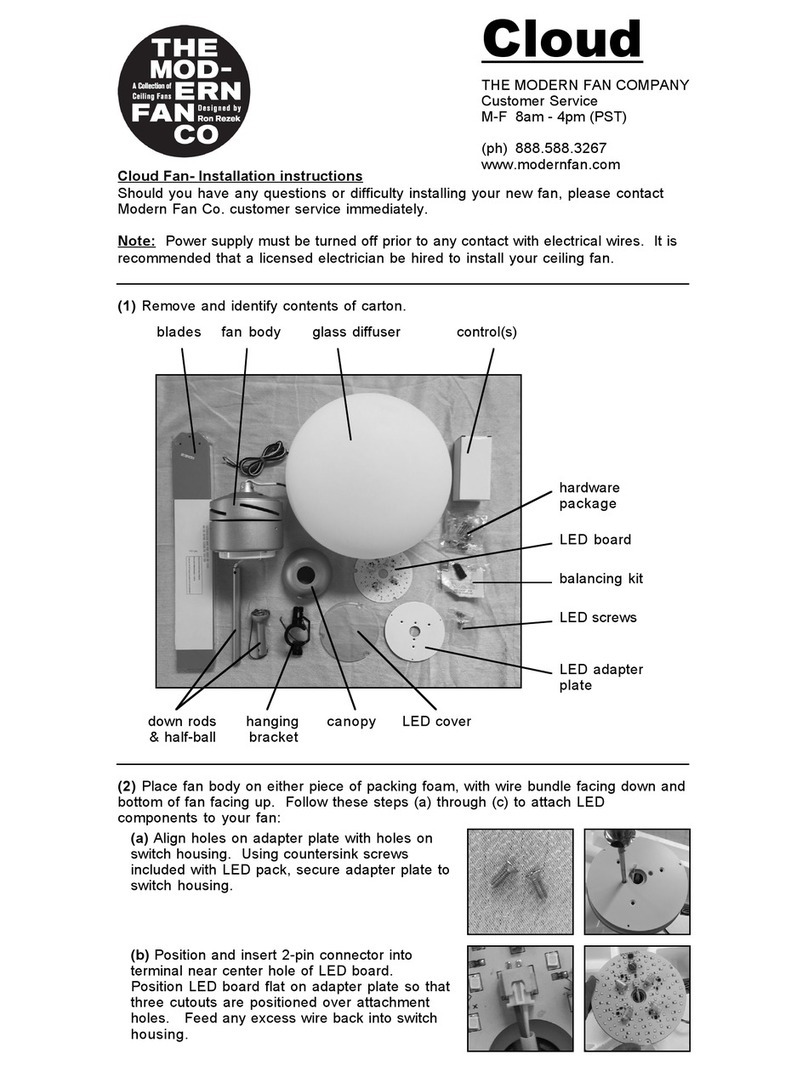
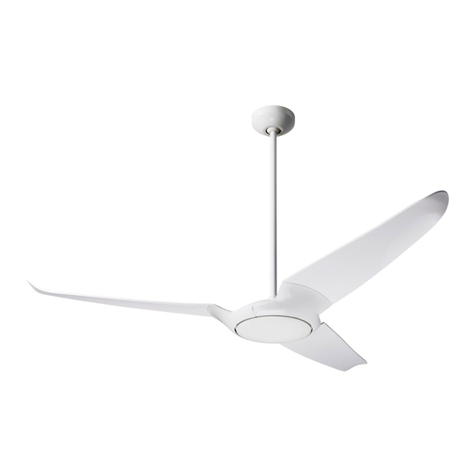
Modern Fan Co Pensi User manual
Other Modern Fan Co Fan manuals
Modern Fan Co
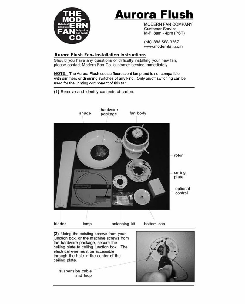
Modern Fan Co aurora flush User manual
Modern Fan Co
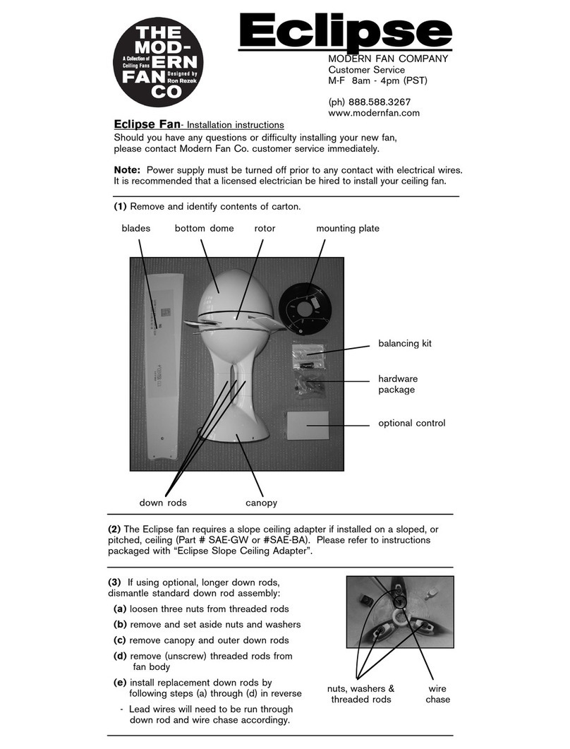
Modern Fan Co Eclipse User manual

Modern Fan Co
Modern Fan Co Torsion User manual

Modern Fan Co
Modern Fan Co Stella User manual

Modern Fan Co
Modern Fan Co Ball User manual

Modern Fan Co
Modern Fan Co Altus User manual

Modern Fan Co
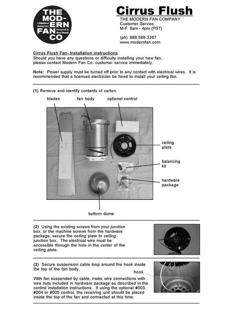
Modern Fan Co Cirrus User manual

Modern Fan Co
Modern Fan Co Velo DC VEL Series Quick start guide
Modern Fan Co
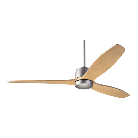
Modern Fan Co Arbor DC Series Quick start guide

Modern Fan Co
Modern Fan Co Velo Flush User manual
Popular Fan manuals by other brands

Harbor Breeze
Harbor Breeze RLG52NWZ5L manual

Allen + Roth
Allen + Roth L1405 instruction manual

ViM
ViM KUBAIR F400 ECOWATT Technical manual

HIDRIA
HIDRIA R10R-56LPS-ES50B-04C10 user guide

BLAUBERG Ventilatoren
BLAUBERG Ventilatoren CENTRO-M 100 L user manual

Triangle Engineering
Triangle Engineering HEAT BUSTER SPL Series owner's manual

