manuals.online logo
Brands
  1. Home
  2. •
  3. Brands
  4. •
  5. Modern Fan Co
  6. •
  7. Fan
  8. •
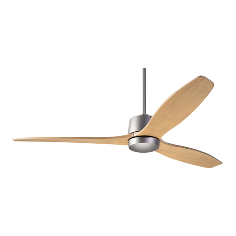
  9. Modern Fan Co IC/Air3 DC Series Quick start guide

Modern Fan Co IC/Air3 DC Series Quick start guide

Most Modern Fan Co. products have been in our assortment for several
years or longer. As we continually work to improve product performance
and user experience, we occasionally introduce subtle (and sometimes
dynamic) product changes. These can affect the steps associated with
assembly and installation of our products depending on when a fan
was produced.
The instructions posted here are intended to represent our most current
product versions and configurations and the associated installation
steps. If your fan or parts of your fan do not appear to match what is
included here, please contact customer service for guidance and support
in identifying which version of a fan you may have and provision of the
associated installation instructions which correspond to that version.
If in doubt, or if you have any questions at all related to assembly,
installation or operation of your fan, please contact us!
A note about our
online installation instructions:
709 Washington Street, Ashland, OR 97520
tel 888-588-3267, fax 541-482-8418
[email protected]
modernfan.com
Please read and save
these instructions.
If you have any
questions while
installing your fan,
call us first!
IC/Air3 DC
Installation Instructions
and Owners Manual
Customer Service
Monday–Friday, 8am–4pm (PST)
tel 888-588-3267
Safety Instructions and Warnings .....2
Fan Installation ..........................................4
Control Installation and Wiring ..........7
Troubleshooting ......................................12
Maintenance ............................................14
Warranty......................................................15
Models: IC3–XX–XX–XX–XX(X)–XX
Net Weight of Fan: 15.0 lbs (6.8 kgs)
Safety Instructions and Warnings
2
Please read all safety instructions prior to installing your ceiling fan
and save this document for future reference. If you are in doubt with
any of the information provided, we recommend that you consult
or hire a qualified electrician to install your outlet box and ceiling fan.
If you have any questions or difficulty installing your fan,
call Modern Fan Co customer service at (888) 588-3267.
Note: This fan is rated and marked as “Suitable for use in Damp Locations.” This
fan is suitable for installation in interior locations protected from weather and subject
to moderate degrees of moisture, such as some basements, barns, cold storage
warehouses, and similar locations, and also partially protected locations such as under
canopies, marquees, roofed open porches, and similar locations. This is not rated,
nor intended for use in applications classified as Wet Locations.
WARNING
Circuit Breaker
POWER OFF
Warning – To reduce the risk of fire, electrical shock, or personal
injury please observe the following:
Mount fan to outlet box marked “Acceptable for Fan Support” and use
mounting screws provided with the outlet box. Note: Most outlet boxes
commonly used for light fixtures are not acceptable for fan support and may
need to be replaced. Consult a qualified electrician if in doubt.
Prior to installation or servicing always disconnect the power by turning off the
circuit breakers to the outlet box and associated wall switch location. If you
cannot lock the circuit breaker in the off position, securely fasten a prominent
warning device, such as a tag, to the service panel.
Do not bend the blade brackets when installing the blades, balancing the
blades, or cleaning the fan. Do not insert foreign objects in between
rotating fan blades.
Disconnect the electrical supply circuit to the fan before installing light kit.
Do not use this fan with any solid-state speed control device other than one
provided or approved by the manufacturer.
This fan must be installed with an isolating wall control/switch.
All wiring must be in accordance with national and local electrical codes
ANSI/NFPA 70. If you are unfamiliar with wiring, use a qualified electrician.
Use this unit only in the manner intended by the manufacturer. If you have
any questions contact the Modern Fan Co at (888) 588-3267.
Use only Modern Fan Co replacement parts.
3
Installation Preparation
Make sure the installation
site you choose allows the
fan blades to rotate without
any obstruction. Allow a
minimum clearance of 7 feet
(2.1 meters) from the floor
to the blades and 30 inches
(76 cm) from the wall to the
end of the blades.
Your new ceiling fan
will require a grounded
electrical supply line of
120 volts AC, 60 Hz,
15 amp circuit. The outlet
box must be securely
anchored and capable of
withstanding a load of
35 lbs (15.9 ww kg).
WARNING
WARNING
Flat Ceiling Mount Angled Ceiling Mount
If you are using an outlet box for wall control installation, the
wires coming from the wall control must be grounded using the attached green wire.
After making wire connections, the wires should be spread apart with the grounded
conductor and the equipment-grounding conductor on one side of the outlet box and
the ungrounded conductor on the other side of the outlet box.
The splices after being made should be turned upward and pushed carefully up
into the outlet box.
This device complies with Part 15 of the FCC Rules. Operation
is subject to the following conditions: (1) the device may not cause harmful interference,
and (2) this device must accept any interference received, including interference that
may cause undesired operation.
WARNING
WARNING
Control Installation and Wiring
Fan Location
Minimum of
7 feet (2.1m)
Minimum of
30 inches (76 cm)
Support Structure
Ceiling
Outlet Box
(required)
Ceiling
Outlet Box
(required)
1
Fan Installation
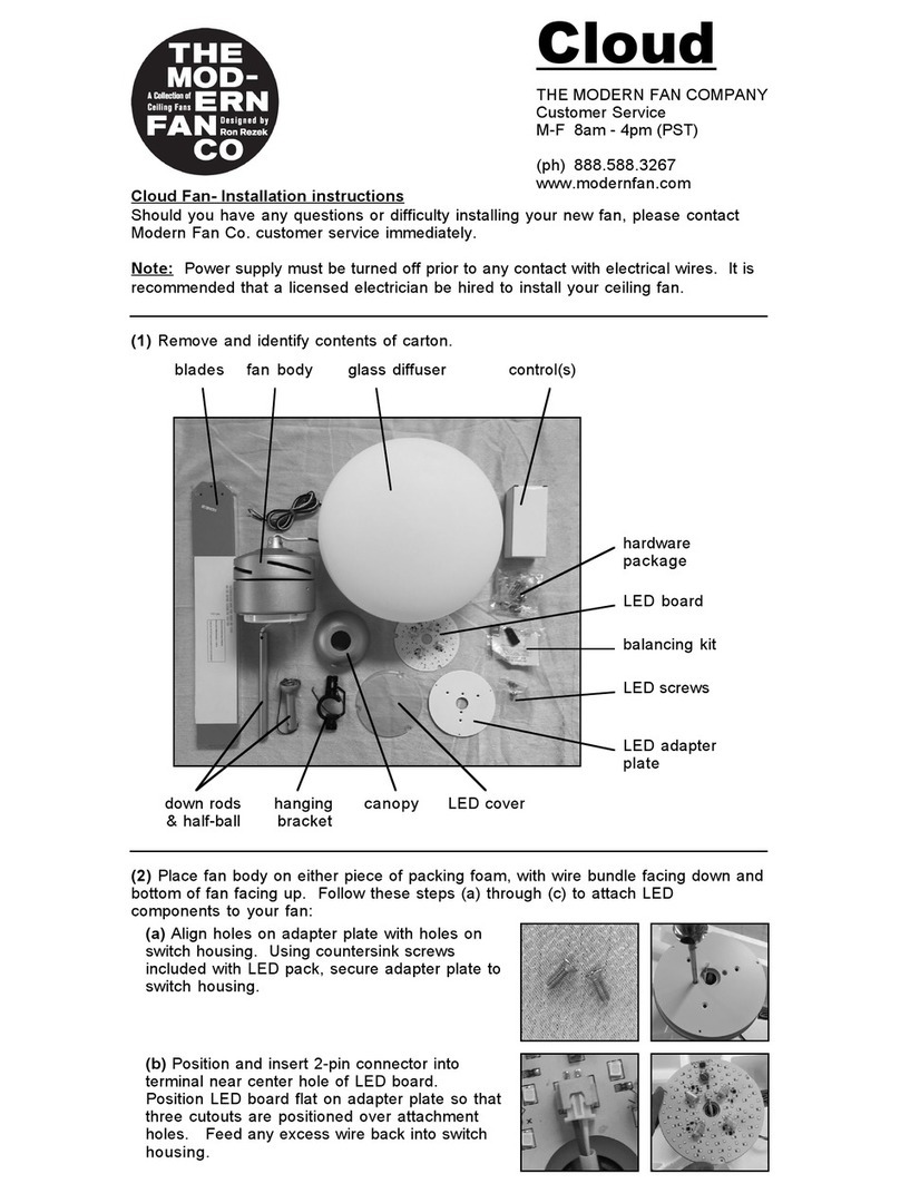
Remove and identify contents of carton.
4
Instructions
Tools Needed
A stepladder, phillips
head screwdriver and a
wire stripper
hanging
bracket
hardware
pack
down
rods
blades
control(s)
light platefan body canopy
screw
covers
balancing
kit
bottom cap
Optional Light Kit parts:
LED board
LED cover
screws
glass
diffuser
blade
arm spur
blade screws with
rubber washers
blade screw
cover
If your fan was ordered with the optional LED light kit, it may have been
pre-installed for you. If not, continue with Step 2 here. If your fan was not ordered
with the optional light kit, proceed to Step 3. Keep in mind, the optional LED
can be ordered and added to your fan at a later date.
To install optional LED, carefully place fan body (bottom side up) on top of either
piece of packing foam. Take care to protect wires and fan body from damage.
Place LED board on light plate so that three cutouts/notches of the LED board
are positioned over screw holes on light plate. Carefully insert 2-pin connector
into port on LED board. If excess wire length is protruding from bottom of fan,
gently pull the blue and white wires from the top side of fan to reduce length on
underside of fan. Place plastic LED cover over LED board with holes aligned for
attachment. Using the three screws packaged with LED cover, secure the cover
and the LED board to the light plate.
Place the fan body on either piece of the foam packaging in a manner so as to
avoid damage to the light kit lead wires or the LED cover on the underside of
the fan. Position a blade over a blade arm making sure that the outer edges are
fitted under the blade arm spurs. While applying a bit of upward pressure on the
blade tip, use the screws and rubber washers from the hardware package to
secure the blade in place. Repeat for additional blade(s). Carefully position the
blade screw covers over the blade arms and snap into place.
2
3
5
WARNING
See Page 2
POWER OFF
Circuit Breaker
Fan Installation (continued)
6
remove stopper
screw and loosen
hex screw
canopy
remove
half-ball and
stopper pin
reinstall half-ball,
stopper pin and
tighten set screw
reinstall and
tighten stopper
screw
install hanging
bracket
tighten
collar hex
screw
place fan
in bracket
Remove down rod stopper screw from fan body and loosen collar hex screw
with hex key (included in hardware pack). Remove half-ball from down rod by
loosening set screw and removing stopper pin, setting aside for Step 5. Run
lead wires from fan body through selected down rod and fit down rod into fan
body collar, taking care not to pinch or damage wires. Align holes in down rod
with hole in collar and reinstall stopper screw. Firmly tighten stopper screw
and hex screw against down rod.
Note: If ceiling height allows, a longer down rod will improve air flow
performance. However, blades must be at least 7 feet above the floor.
Run lead wires through center hole of canopy and gently set canopy on fan
body. Then run lead wires through half-ball, reinstall stopper pin and tighten half-
ball set screw.
Using screws provided with junction box, securely attach hanging bracket to
ceiling junction box. Junction box must be visibly marked as “Acceptable for Fan
Support.” It is recommended that the flat washers and lock washers from the
hardware pack be used for added security. Lift fan to ceiling and set half ball in
the hanging bracket so that the ridge on the hanging bracket is seated in the
slotted channel in the half ball.
4
5
7
Identify control components from control package(s). In addition to a receiving
unit, your fan may have been ordered with a wall control (transmitter), a handheld
remote control (transmitter) or both.
Insert receiving unit into hanging bracket
(between bracket arms) and make wire
connections according to wire colors, labels and
diagram below. If ordered, install wall switch into
wall box, taking note of dip-switch settings and
related instructions referenced below.
6
receiving unit receiving unit
switch
plate
wall
switch
hardware &
wire nuts
batteries
handset
wall clip &
hardware
WARNING
See Pages 2-3
POWER OFF
Circuit Breaker
WARNING!! Power must be disconnected at circuit
breaker prior to any contact with electrical wires.
Wiring Diagram
red motor 1
blue for optional light
white for optional light
antenna
purple motor 2
white
black
gray motor 3
fan or
fan & light
receiving
unit
A/C power in (neutral)
A/C power in (load)
wall
switch
8
Fan Installation (continued)
Once wire connections are completed, remove set
screws on outside of hanging bracket, lift canopy
up to cover receiving unit, wire connections and
hanging bracket, then reinstall set screws on each
side of canopy to secure in place.
7
8
WARNING
See Pages 2-3
POWER OFF
Circuit Breaker
Dimming Selector Switch
The remote handset and wall control ship pre-set for “on/off” operation of the light.
The LIGHT button will turn the light on and off when pressed and released.
To enable dimming function on the remote handset, move the vertically oriented
dip switch down from ON to 1 (or from X to D). On the wall control, move the
right (or lower) dip switch from ON to 2 (or from X to D). Dip switches are located
inside the battery cover of the remote handset and on the left side of the wall
control. See image below.
With dimming enabled, pressing and holding the LIGHT button will increase or
decrease brightness, with the minumum and maximum light levels indicated by
a “chirp” from the receiver.
Universal or Dedicated RF Channels
The remote handset and wall control ship pre-set to a “Universal” or common RF
channel. If you have multiple fans in close proximity, you will want to set the remote
handset and/or wall control to an “Individual” (or unique) channel. To select the
“Individual” channel on the remote handset, move the horizontally oriented dip
switch from ON to 1 (or from U to I). On the wall control, move the left (or upper)
dip switch from ON to 1 (or from U to I). See images above.
Inside remote handset
Dip Switches:
Left side of wall control
Universal or
Individual
Channel
On/Off or
Dimming
Top
Bottom
9
Align slotted openings in bottom cap (or glass diffuser if optional LED is
installed) with small posts on underside of fan body. Push bottom cap (or glass
shade) up and gently rotate into place. There is no need to forcefully over
tighten bottom cap (or glass).
9
10
Device Pairing
If using the individual RF channel(s),
you will need to pair your remote
handset and/or wall control with the
receiver. Begin by turning power off
at the wall control, at the main switch
leg, or at the circuit breaker if there
is no wall control or on/off switch in
use. Switch the power supply back
on and immediately press and firmly
hold down the LIGHT and FAN
OFF buttons simultaneously for
10 seconds. If using both a remote
handset and wall control with a fan,
repeat these pairing steps with the second device. If using a handset or wall
control only, repeat the pairing steps again with that device. This “pushes out”
the Universal code from the receiver memory and will avoid interference from
any nearby controls set to the Universal channel.
Note: If your installation does not include a switch leg, you may need a
second person to execute the pairing steps described below immediately after
breaker is turned on.
Test the pairing by pressing the SPEED+ button once. Your fan will pause and
make several subtle movements prior to achieving a normal spinning motion. If fan
does not respond, verify that power is on at the breaker and repeat pairing steps
above. If fan does respond as expected, press the FAN OFF button, wait for fan to
come to complete stop and then test pairing of second transmitter (if applicable).
bottom cap light diffuser
10
11 The ON/OFF switch on the bottom of your wall control (transmitter) terminates
power to the fan. This switch must be in the “ON” position for your fan to receive
commands and to operate. Alternatively, you may use an on/off toggle switch at
the wall box in combination with a remote control handset (transmitter). In some
cases, when no switch leg is present, your fan may have continuous power to
the receiving unit.
Your fan has six speeds, each of which can be selected by pressing the
SPEED+ or SPEED- buttons on the wall control or the remote handset.
The fan will start at speed 1 (slowest) and the receiving unit will provide
audible feedback (using short “chirps” and longer “beeps”) to indicate speed
progression as follows:
Fan Operation
Fan Installation (continued)
The REV button can be used to change the direction of the fan for summer or
winter operation. Allow adequate time for the fan to come to a complete stop
and then restart in the opposite direction. The fan will return to the same speed
at which it was operating prior to the REV button being used. Alternatively, you
can leave your fan in the summer (downward) airflow setting and simply set it to
a low speed for winter use. This method will also achieve effective destratification
(recirculation) of warmer air trapped at the ceiling level.
The LIGHT button turns the light on and off with each contact. If dimming is
enabled, pressing and holding the light button will achieve continuous dimming
(cycling all the way down then all the way back up) until you release the LIGHT
button. The top and bottom of the dimming range are indicated by an audible
“chirp” from the receiving unit.
If you slide the ON/OFF switch to “OFF”, the fan will return to the same speed
and directional setting (and light setting if an optional light is installed) when you
slide the switch back to the “ON” position. The same memory function will exhibit
if you are using an ON/OFF toggle switch in combination with a handheld remote
control (transmitter).
It is recommended that when the fan is not in use for an extended duration, the
ON/OFF switch on the wall control (transmitter) should be moved to the “OFF”
position. Similarly, if you are using an ON/OFF toggle switch in combination with
a handheld remote control (transmitter), it is recommended that the switch be
turned “OFF” when the fan is not in use for a continuous duration.
1 beep = speed 4
2 beeps = speed 5
3 beeps = speed 6 (fastest)
1 chirp = speed 1 (slowest)
2 chirps = speed 2
3 chirps = speed 3
Audible fan speed indicators:
11
12 The rotor and motor of your fan have been dynamically tested and balanced
during manufacturing and production. In addition, the blades have been matched
to the nearest gram to ensure well balanced operation. Furthermore, a blade
balancing kit has been included with your fan. Please refer to the instructions
packaged with the balancing kit should your fan require additional balancing.
Fan Balancing
12
Troubleshooting
Blades don’t turn...
• Verify that the required receiving unit has been installed and wire connections have
been made according to the installation instructions.
• Verify that there are no physical obstructions preventing motor & blades from spinning
(push blades by hand to confirm that they spin freely).
• Confirm power has been turned on at circuit breaker and wall switch.
Light doesn’t work in the on position...
• Check wire connections at ceiling and wall control.
• Confirm that LED wire leads and terminal block is properly connected to LED board.
Fan wobbles...
• Make sure hanging bracket and mounting hardware at ceiling is secure and firmly
fastened.
• Be sure ridge in hanging bracket is seated in the half-ball slot.
• Check that stopper screw (or stopper pin) and set screws are firmly tightened where
down rod is attached to the fan body.
• Remove and reinstall two blades in opposite positions.
• Use blade balancing kit as instructed.
Note: blade sets should not be inter-mixed as they are weight matched when
packaged together.
Please read all installation instructions carefully. After reviewing the following
troubleshooting tips, if you are unable to solve a problem with the installation or operation
of you fan, please contact customer service for additional assistance.
IMPORTANT: Do not return a fan or fan parts without first contacting us
for troubleshooting assistance.
If we are unable to resolve a problem over the phone, a replacement fan or part will be
provided and a prepaid shipping label will be issued for returning the defective product.
Returns cannot be accepted without a Company issued return label.
For the return of non-defective, un-installed merchandise, please contact your dealer.
Often, noises such as ticking or humming can be caused by loose parts or structural
factors in the ceiling. Please double check that all screws and parts are firmly tightened,
including the outlet box from which the fan is hung. Next, review the troubleshooting
tips listed below.
As stated in the warranty, Modern Fan Co. is not liable for costs incurred related to
installation labor or equipment. Be sure to test all functions of your fan, and if need be,
contact customer service while your contractor/electrician is still on site.
Troubleshooting Checklist
13
Fan makes repetitive ticking noise...
• Check for obstructions in rotor path.
• Make sure mounting hardware at ceiling is secure.
• Make sure all other hardware and blade attachments are tight.
• Give fan adequate “break in period” of several hours to several days then repeat
steps above.
Fan makes humming noise...
• Be sure you are using the control set (including receiver) that was supplied with
your fan.
• Be sure that all ttings (light kit, bottom dome, canopy, etc.) are rmly secured.
Loose parts will often cause vibrational noise or humming. Removal and re-attachment
can sometimes remedy such resonant vibrational noise.
Fan (or light) not responding to hand-held remote or wall mounted RF signal...
• Check that all wire connections are secure and made as instructed.
• Verify that power is on and reaching the receiver (using a voltmeter).
• Review and repeat pairing instructions.
• Be sure to firmly press the center area of the buttons on you handset or wall control.
• Verify that batteries are installed with proper polarity as indicated inside battery cover.
Customer Service
Monday–Friday, 8am–4pm (PST)
tel 888-588-3267
[email protected]
Maintenance
Before servicing or cleaning your fan, switch power off at service panel and lock the
service disconnecting means to prevent power from being switched on accidentally.
When the service disconnecting means cannot be locked, securely fasten a prominent
warning device, such a tag, to the service panel.
• Your fan uses maintenance free, sealed bearings. There is no need to lubricate the
motor bearings or inner shaft.
• It is recommended that you inspect your fan at least annually to conrm that all blade
screws and mounting hardware remain securely fastened as when originally installed.
• Periodic surface cleaning may be necessary depending on the amount of dust and
particulate accumulation on the blades and surfaces of your fan. Use a damp cloth.
If necessary, a light, non-abrasive soap solution may be used.
• If installed in a coastal, humid environment, regular surface cleaning may be necessary
in order to avoid deterioration or oxidizing effects of salt or other corrosive elements.
A Damp Location rating is not an assurance of finish durability. Preventative measures
should be taken dependent on the environmental exposures your fan will undergo in
order to preserve and protect the finish quality and appearance of your fan.
• If a wobble develops over time, you may need to rebalance your fan following the
instructions that were included with the balancing kit. If the blades have warped,
twisted, bent or become uneven in weight distribution, replacement blades may be the
best course of action and can be purchased by contacting The Modern Fan Co. directly.
• If a noise develops over time (clicking, ticking, humming or otherwise), refer to the
troubleshooting section of this manual (pages 12-13). If you are unable to remedy the
issue, contact Modern Fan customer service for further assistance.
Use this unit only in the manner intended by the manufacturer. If you have any
questions contact The Modern Fan Co.
14
WARNING
See Pages 2-3
POWER OFF
Circuit Breaker
Customer Service
Monday–Friday, 8am–4pm (PST)
tel 888-588-3267
[email protected]
Lifetime Limited Warranty
All products manufactured and sold by The Modern Fan Co. meet the highest industry
standards. We use only the finest materials and production processes resulting in quality
ceiling fans backed by the following warranty:
Motors (dry locations):.......................................................................................................Lifetime
Motors (damp locations): ................................................................................................10 years
Light Kits:...............................................................................................................................3 years
Component Parts (switches, capacitors, blades): .........................................................1 year
Finishes: ...................................................................................................................................1 year
Wall and remote controls:....................................................................................................1 year
Limitations:
•This warranty covers failure of fan due to defect(s) in materials or workmanship and
does not apply to defects, malfunctions or failures which are caused by repairs by
persons not authorized by us, use of parts or accessories not authorized by us,
mishandling, improper installation, modifications or damage to the fan while in your
possession, or unreasonable use.
• This warranty applies only to products sold and installed within the United States.
• This warranty extends only to the original user or consumer purchaser of the ceiling fan.
•This warranty applies to private residential use of ceiling fans only. Use of products in
commercial applications is backed by a 10-year “motor” warranty. All other aspects of
this warranty remain the same.
• This warranty only covers the replacement or repair of ceiling fan or parts as specified
above, and does not cover any other costs incurred related to installation labor or
equipment, or shipping of fan or fan parts.
• No other expressed warranty is given. The repair or replacement of a product is your
exclusive remedy. Any implied warranty of merchantability or fitness is limited to the dura-
tion of this written warranty. In no event shall the Company be liable for consequential or
incidental damages. Some states do not allow exclusion or limitation of consequential
or incidental damages, so the above exclusions or limitations may not apply to you.
Claims:
Prior to submitting a claim for a defective or failed fan, or prior to removal of your fan from
its installation location, please contact customer service (888-588-3267) for troubleshoot-
ing assistance. Often our personnel can diagnose the cause of a nonfunctioning fan and
provide either operational instructions, or replacement parts/components that don’t require
your fan be removed from the ceiling.
If we are unable to remedy the problem in this way, upon receipt of proof of purchase
(including date and location of sale), we will provide the necessary replacement parts or
fan as specified by this warranty, or provide instructions and an authorization for return
of the product for diagnosis, repair or replacement.
15
V2019/02
The Modern Fan Company, Inc.
709 Washington Street, Ashland, Oregon 97520
tel 888-588-3267, fax 541-482-8418
[email protected]
modernfan.com

This manual suits for next models

1

Other Modern Fan Co Fan manuals

Modern Fan Co Ball User manual

Modern Fan Co

Modern Fan Co Ball User manual

Modern Fan Co Cloud User manual

Modern Fan Co

Modern Fan Co Cloud User manual

Modern Fan Co Arbor DC Series Quick start guide

Modern Fan Co

Modern Fan Co Arbor DC Series Quick start guide

Modern Fan Co Stella User manual

Modern Fan Co

Modern Fan Co Stella User manual

Modern Fan Co Velo Flush User manual

Modern Fan Co

Modern Fan Co Velo Flush User manual

Modern Fan Co DC Slim User manual

Modern Fan Co

Modern Fan Co DC Slim User manual

Modern Fan Co Velo DC VEL Series Quick start guide

Modern Fan Co

Modern Fan Co Velo DC VEL Series Quick start guide

Modern Fan Co Cirrus User manual

Modern Fan Co

Modern Fan Co Cirrus User manual

Modern Fan Co Torsion User manual

Modern Fan Co

Modern Fan Co Torsion User manual

Modern Fan Co Pensi User manual

Modern Fan Co

Modern Fan Co Pensi User manual

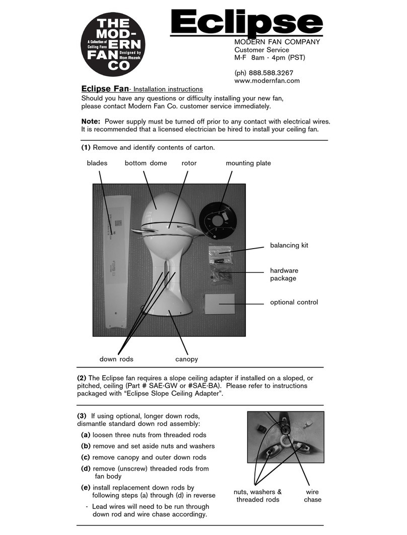
Modern Fan Co Eclipse User manual

Modern Fan Co

Modern Fan Co Eclipse User manual

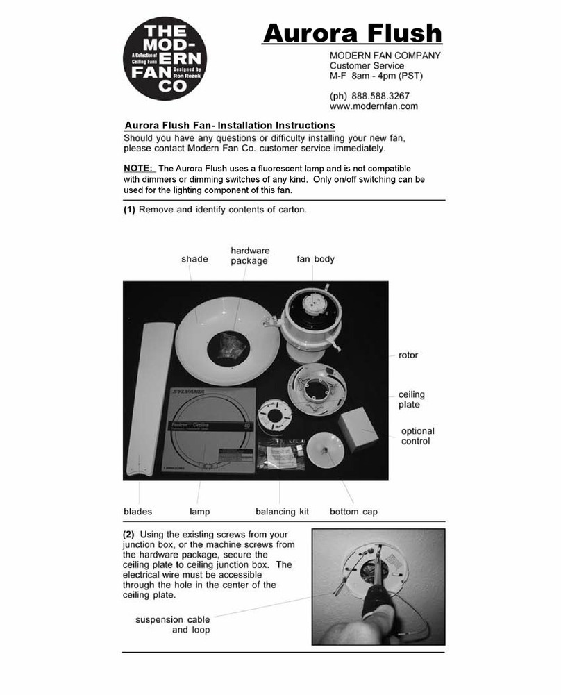
Modern Fan Co aurora flush User manual

Modern Fan Co

Modern Fan Co aurora flush User manual

Modern Fan Co Altus User manual

Modern Fan Co

Modern Fan Co Altus User manual

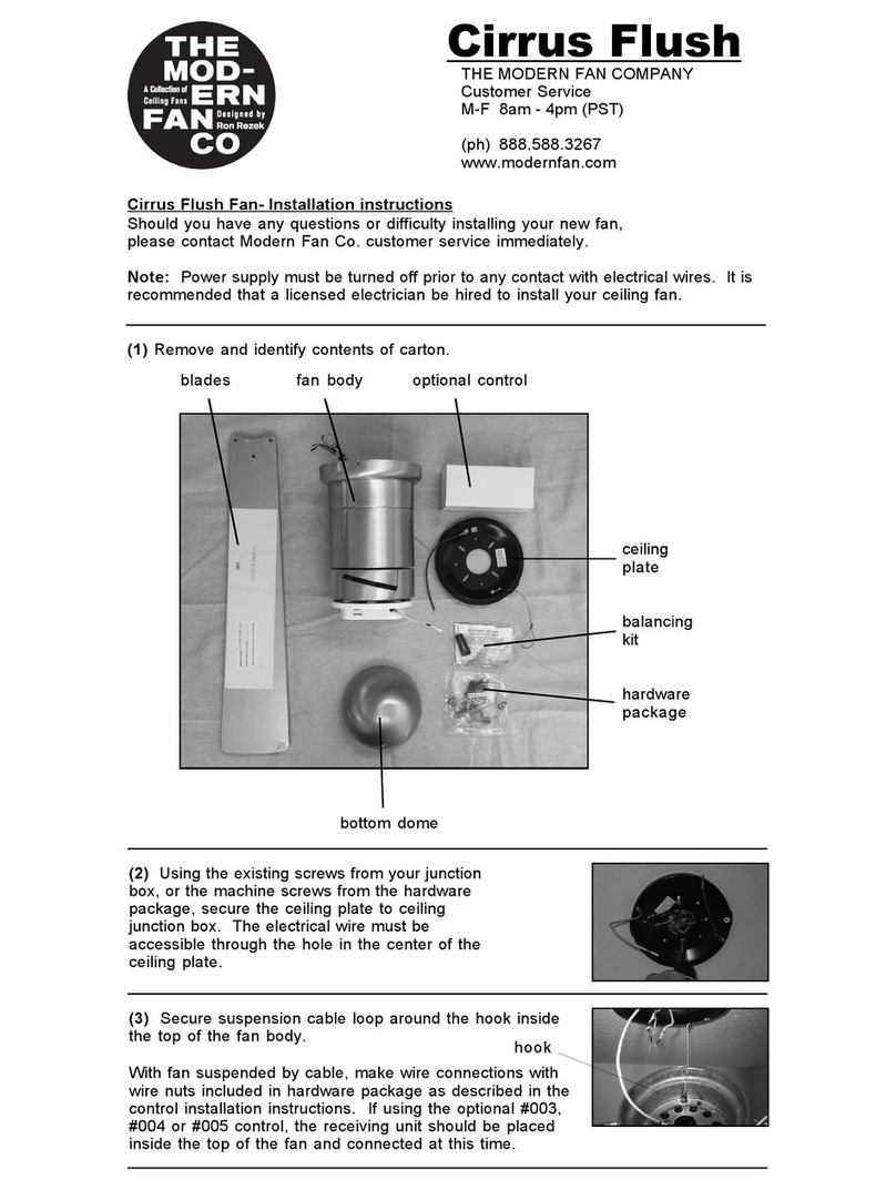
Modern Fan Co Cirrus Flush User manual

Modern Fan Co

Modern Fan Co Cirrus Flush User manual

Popular Fan manuals by other brands

Casablanca Candelier owner's manual

Casablanca

Casablanca Candelier owner's manual

iStarUSA WA-FANAC120 installation guide

iStarUSA

iStarUSA WA-FANAC120 installation guide

Vivax FT-10WPR instruction manual

Vivax

Vivax FT-10WPR instruction manual

Bestron DLHB42S instruction manual

Bestron

Bestron DLHB42S instruction manual

Somogyi Elektronic home PVRO 40 instruction manual

Somogyi Elektronic

Somogyi Elektronic home PVRO 40 instruction manual

Orbegozo SF 0640 instruction manual

Orbegozo

Orbegozo SF 0640 instruction manual

Yard force LF C36 Original instructions

Yard force

Yard force LF C36 Original instructions

NuTone 765hl instructions

NuTone

NuTone 765hl instructions

ATMOX 01-360-100 quick start guide

ATMOX

ATMOX 01-360-100 quick start guide

Olimpia splendid Caldo Whisper Instructions for installation, use and maintenance

Olimpia splendid

Olimpia splendid Caldo Whisper Instructions for installation, use and maintenance

Renson Healthbox II manual

Renson

Renson Healthbox II manual

PROAIRA SP15-16AZ manual

PROAIRA

PROAIRA SP15-16AZ manual

Hunter 28482 Parts guide

Hunter

Hunter 28482 Parts guide

Perel TV76502 user manual

Perel

Perel TV76502 user manual

nilan CTS602 HMI Software instructions

nilan

nilan CTS602 HMI Software instructions

Fanaway LED EVO1 installation instructions

Fanaway

Fanaway LED EVO1 installation instructions

COOLFORT CF-2029 Manual instruction

COOLFORT

COOLFORT CF-2029 Manual instruction

Brink Flair 325 Installation regulations

Brink

Brink Flair 325 Installation regulations

manuals.online logo
manuals.online logoBrands
  • About & Mission
  • Contact us
  • Privacy Policy
  • Terms and Conditions

Copyright 2025 Manuals.Online. All Rights Reserved.