manuals.online logo
Brands
  1. Home
  2. •
  3. Brands
  4. •
  5. Modern Fan Co
  6. •
  7. Fan
  8. •
  9. Modern Fan Co Cirrus User manual

Modern Fan Co Cirrus User manual

A note about our online installation instructions:
Most Modern Fan Co. products have been in our assortment for several years
or longer. As we continually work to improve product performance and user
experience, we occasionally introduce subtle (and sometimes dynamic)
product changes. These can affect the steps associated with assembly and
installation of our products depending on when a fan was produced.
709 Washington Street • Ashland, OR 97520 • (tel) 888.588.3267 • (e) [email protected]
w w w . m o d e r n f a n . c o m
The instructions posted here are intended to represent our most current product versions and
configurations and the associated installation steps. If your fan or parts of your fan do not appear to
match what is included here, please contact customer service for guidance and support in
identifying which version of a fan you may have and provision of the associated installation
instructions which correspond to that version.
If in doubt, or if you have any questions at all related to assembly, installation or operation of your
fan, please contact us!
THE MODERN FAN COMPANY
Customer Service
M-F 8am - 4pm (PST)
(ph) 888.588.3267
www.modernfan.com
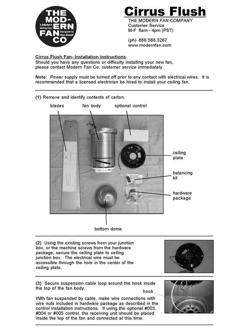
(1) Remove and identify contents of carton.
Cirrus Fan- Installation instructions
Should you have any questions or difficulty installing your new fan,
please contact Modern Fan Co. customer service immediately.
Note: Power supply must be turned off prior to any contact with electrical wires. It is
recommended that a licensed electrician be hired to install your ceiling fan.
Cirrus
control(s)
balancing kit
hanging
bracket
blades
hardware
fan body
bottom
dome
extra down rod
(2) Using the existing screws from your junction box, or the
machine screws from the hardware package, secure the
hanging bracket to the ceiling junction box.
(3) The Cirrus fan ships in a 17” long configuration. If ceiling height allows, using a
longer down rod will increase airflow and efficiency. If you would like to install a
longer down rod, follow steps (a) through (d). Otherwise, proceed to step (4).
(a) Remove stopper pin and half ball from small down rod
by loosening set screw on half ball. Set these parts and
canopy aside for reinstallation.
stopper pin
set screw
canopy
(b) Remove top dome by loosening screw on fitting
against down rod, above top dome. Slide fitting and
dome up down rod and set aside for reinstallation.
fitting
top dome
(c) Slightly loosen three screws
where down rod is attached to
motor and remove the cotter pin
and through pin assembly. Set all
parts aside for reinstallation.
(d) Remove down rod and run fan wires through selected replacement down rod.
In reverse order, follow steps above to reassemble.
Note: When tightening the three screws where the down rod attaches to the motor.
take care that the down rod is centered evenly. This may require adjustment of the
three screws.
Very Important: The through pin and cotter pin assembly at the base of the down
rod and the stopper pin at the top of the down rod must be reinstalled for a safe
and secure installation of your fan.
(4) Lift fan to ceiling and set half ball in the hanging bracket
so that the ridge on the edge of the hanging bracket is
seated in the slotted channel in the half ball.
(5) Remove set screws on the sides of the
hanging bracket. Lift canopy to ceiling. With slots
on side of canopy aligned with set screws on
hanging bracket, reinstall and tighten set screws
to hold canopy in place.
With fan safely suspended by bracket, make wire connections
with wire nuts included in hardware package as described in
the control installation instructions. If using the optional #003,
#004 or #005 control, the receiving unit should be placed inside the arms of the
hanging bracket and connected now.
(6) Carefully insert blades into rotor slots, and
using pan head screws from hardware package,
secure blades to rotor. Screwdriver and screw
passes through oval holes to access blade and
rotor attachment points.
(7) Install bottom dome by rotating in the clock
wise direction, or if using an optional light, skip
this and proceed to step (8).
(8) To install optional light kit, begin by identifying all parts. Then follow
steps (a) through (e):
glass
socket
hardware
LED
lamp/bulb
ring
stickers
(a) Connect wire leads from the fan to the socket, and using screws from
hardware package, attach socket bracket to switch housing.
(b) To prevent escape of light
into rotor area, apply reflective
stickers to switch housing plate,
covering blade screw slots.
(c) Move the light switch to the
“ON” position.
(d) Align holes on side of ring with holes
on switch housing plate. Secure using
small countersink screws and screwdriver
from hardware package. Start all three
screws before tightening completely.
(9) Your fan is reversible for summer and winter operation.
The reverse switch is located on the side of the switch
housing. The LEFT position is for summer and the RIGHT
position is for winter.
reverse switch
(e) Install lamp. Then align
channels/grooves on glass diffuser with
tabs on ring and rotate glass until firmly
tight. Do not over tighten.
(11) The rotor and motor of your fan have been dynamically balanced at the factory.
In addition, the blades have been matched to the nearest gram to ensure a well
balanced ceiling fan. Furthermore, a blade balancing kit has been included with your
fan. Please refer to the instructions packaged with the balancing kit should your fan
require additional balancing.
(10) Install wall control as described in the control installation instructions (unless
using handheld remote only).
709 Washington Street • Ashland, OR 97520 • (tel) 888.588.3267 • (e) [email protected]
w w w . m o d e r n f a n . c o m
Modern Fan Co. Control Options
for AC motors and LED light kits
When ordering your fan, you should have selected the control most
appropriate for your fan and electrical requirements.
Controls are intended for use with one fan (except #009A/009B as noted).
A basic fan control used to operate a fan only, providing four
speeds. *Not compatible with remote control
For operation of a fan with light. Requires two
circuits (three wires). Provides four speeds and full
range dimming. *Not compatible with remote control
Designed for independent operation of a fan and light using
only one circuit (two wires). Provides three speeds and full
range dimming or “on/off” switching and wires into wall box.
Includes wall switch, switch plate and receiver.
Designed for independent operation of a fan and light using
only one circuit (two wires). Provides three speeds and full
range dimming or “on/off” switching. Includes handset,
receiver, two AAA batteries and comes with a wall hanging
bracket for handset.
A combination control set providing three speeds and full
range dimming or “on/off” switching from wall control and/or
remote handset. Includes one receiver, a remote handset with
hanging bracket, two AAA batteries and wall control with
switch plate.
#FC-001 Fan Speed Control
#FC-002 Three Wire Fan Speed & Light Control
#FC-003-LED Handheld Remote Control
#FC-004-LED Two Wire Fan Speed & Light Control
#FC-005-LED Two Wire Wall Control with Remote Handset
A three speed fan control designed to control two fans
(#009A) or three to five fans (#009B) on a single circuit.
Separate control/switching of lights must be planned if this
control is to be used for fans with lights. For AC motors only.
*Not compatible with remote control
#FC-009A/009B Multi-Fan Control (sold separately from fans)
Installation Instructions: With power turned off at breaker, make wire
connections from the fan to the power supply at the ceiling and from the
control to power at wall box as shown in the wiring diagrams below.
Note: For #009A or #009B, refer to printed instructions included in control
box/packaging.
Fan
Cap off BLUE wire
(unused load for light)
BLACK motor
WHITE neutral
AC in Load
AC in Neutral
AC in
Fan
BLUE (light)
BLACK
to motor
WHITE (neutral motor)
AC in Neutral
AC in
BLACK/White
AC in load
BLACK (motor)
BLUE
to light
GREEN- connect ground
wire to grounded
hanging bracket or
mounting plate
GREEN-
connect
ground wire
to grounded
hanging
bracket or
mounting
plate
GREEN
Ground
GREEN
Ground
#001 Wiring Diagram
#002 / #002ND Wiring Diagram
On/Off Switch (w/ #003) or
Wall Switch (w/ #004/#005 )
Fan
BLUE
BLACK
WHITE
AC in
Neutral
AC in
AC in
Load
GREEN-
connect
ground wire
to grounded
hanging
bracket or
mounting
plate
Green
Ground
#003 / #004 / #005 Wiring Diagram
Receiving
Unit
Load
WHITE
BLACK
Cap off ORANGE*
wire if present
(unused neutral for light)
ORANGE (neutral light)
BLACK (motor)
WHITE (neutral motor)
BLUE (light)
BLACK
to motor
RU
ORANGE
Antenna
WHITE
BLACK
BLUE
To Black (motor load)
WHITE
BLACK
to A/C Power In (Neutral)
#003, #004 and #005 Receiving Unit Wiring Instructions:
With fan suspended from ceiling and with power off at breaker box, make
wire connections as shown below. The receiving unit sits in the ball hanging
bracket of most models as pictured (a), or in the upper portion of the fan
body in flush mount models (b).
(a)
(b)
Receiving Unit Placement:
While there is ample room for the receiving unit as shown here, the wires
can sometimes become difficult to manage in the space available. Trimming
excess wire before making connections can ease wire management.
Tip: Splicing lighter gauge wire to the power supply and positioning the
heavier wires up into the junction box can also ease wire management.
to A/C Power In (Load)
To White (motor neutral)
To Blue (light load)
ORANGE
To Orange (light neutral)
The remote handset (#003/#005) and wall control (#004/#005) ship pre-set
for “on/off” operation of the light. The LIGHT button will turn the light on
and off when pressed and released.
To enable dimming function on the remote handset, move the vertically
oriented dip switch down from ON to 1 (or from X to D). On the wall control,
move the right (or lower) dip switch from ON to 2 (or from X to D). Dip
switches are located inside the battery cover of the remote handset and on
the left side of the wall control. See image below.
With dimming enabled, pressing and holding the LIGHT button will increase
or decrease brightness, stopping at the minimum and maximum brightness
levels or when the LIGHT button is released.
Dimming Selector Switch (for #003, #004 and #005 only):
Dip switches:
Universal or Individual RF Channels (for #003, #004 and #005 only)
The remote handset (#003/#005) and wall control (#004/#005) ship pre-set
to a “Universal” or common RF channel. If you have multiple fans in close
proximity, you will want to set the remote handset and/or wall control to an
“Individual” (or unique) channel. To select the “Individual” channel on the
remote handset, move the horizontally oriented dip switch from ON to 1 (or
from U to I). On the wall control, move the left (or upper) dip switch from ON
to 1 (or from U to I). See images above.
After selecting the individual RF channel(s), you will need to pair your
remote handset and/or wall control with the receiver. Begin by turning
power off on the wall control, on the main switch leg or at the circuit breaker
if there is no wall control or on/off switch in use. Switch the power supply
back on and immediately press and firmly hold down the LIGHT and FAN
OFF buttons simultaneously for 10 seconds. If using both a remote
handset and wall control with a fan, repeat these pairing steps with the
second device. If using a handset or wall control only, repeat the pairing
steps again with that device. This “pushes out” the Universal code from the
receiver memory and will avoid interference from any nearby controls set to
the Universal channel.
Left side of wall control
Inside remote handset
On/Off or
Dimming
Universal or
Individual
Channel
Contact Modern Fan Customer Service with any questions related to
installation or operation of your fan.
888-588-3267 or 541-482-8545 • [email protected] • www.modernfan.com
Top
Bottom

Other Modern Fan Co Fan manuals

Modern Fan Co Altus User manual

Modern Fan Co

Modern Fan Co Altus User manual

Modern Fan Co Velo Flush User manual

Modern Fan Co

Modern Fan Co Velo Flush User manual

Modern Fan Co DC Slim User manual

Modern Fan Co

Modern Fan Co DC Slim User manual

Modern Fan Co Cloud User manual

Modern Fan Co

Modern Fan Co Cloud User manual

Modern Fan Co Pensi User manual

Modern Fan Co

Modern Fan Co Pensi User manual

Modern Fan Co Ball User manual

Modern Fan Co

Modern Fan Co Ball User manual

Modern Fan Co aurora flush User manual

Modern Fan Co

Modern Fan Co aurora flush User manual

Modern Fan Co Stella User manual

Modern Fan Co

Modern Fan Co Stella User manual

Modern Fan Co Velo DC VEL Series Quick start guide

Modern Fan Co

Modern Fan Co Velo DC VEL Series Quick start guide

Modern Fan Co Torsion User manual

Modern Fan Co

Modern Fan Co Torsion User manual

Modern Fan Co IC/Air3 DC Series Quick start guide

Modern Fan Co

Modern Fan Co IC/Air3 DC Series Quick start guide

Modern Fan Co Eclipse User manual

Modern Fan Co

Modern Fan Co Eclipse User manual

Modern Fan Co Arbor DC Series Quick start guide

Modern Fan Co

Modern Fan Co Arbor DC Series Quick start guide

Modern Fan Co Cirrus Flush User manual

Modern Fan Co

Modern Fan Co Cirrus Flush User manual

Popular Fan manuals by other brands

Monte Carlo Fan Company 5TQ52XXD-L Series owner's manual

Monte Carlo Fan Company

Monte Carlo Fan Company 5TQ52XXD-L Series owner's manual

Craftmade Chalice CL52 Specifications

Craftmade

Craftmade Chalice CL52 Specifications

Mars Comfort-Aire FB-3630B-MBL Series owner's manual

Mars

Mars Comfort-Aire FB-3630B-MBL Series owner's manual

Supra CALISTA Instructions for use

Supra

Supra CALISTA Instructions for use

Centurion F40/1 instruction manual

Centurion

Centurion F40/1 instruction manual

D+H GVL 8304-K Original instructions

D+H

D+H GVL 8304-K Original instructions

Rubine SETTE Series user manual

Rubine

Rubine SETTE Series user manual

Arbonia Sabiana Maestro MTL-ECM Installation, use and maintenance manual

Arbonia

Arbonia Sabiana Maestro MTL-ECM Installation, use and maintenance manual

Holmes HASF1406 owner's guide

Holmes

Holmes HASF1406 owner's guide

BPS WF Series Installation use and service manual

BPS

BPS WF Series Installation use and service manual

Brink HRV installation instructions

Brink

Brink HRV installation instructions

Holmes HAOF85 owner's guide

Holmes

Holmes HAOF85 owner's guide

Westinghouse WSFTYFE3608 instruction manual

Westinghouse

Westinghouse WSFTYFE3608 instruction manual

KOOLAIR DF-47-TR Mounting instructions

KOOLAIR

KOOLAIR DF-47-TR Mounting instructions

Aiolos SmartAir Installation and operating instructions

Aiolos

Aiolos SmartAir Installation and operating instructions

Chore-Time TURBO series Installation & operator's manual

Chore-Time

Chore-Time TURBO series Installation & operator's manual

Craftmade PIL52 installation guide

Craftmade

Craftmade PIL52 installation guide

DYNABREEZE FA-29114 Instruction User Manual & Warranty

DYNABREEZE

DYNABREEZE FA-29114 Instruction User Manual & Warranty

manuals.online logo
manuals.online logoBrands
  • About & Mission
  • Contact us
  • Privacy Policy
  • Terms and Conditions

Copyright 2025 Manuals.Online. All Rights Reserved.