Modine Manufacturing DBS/DCS Manual

5-594.11
5H0768560001
INSTALLATION AND SERVICE MANUAL
indirect gas-red indoor separated combustion make-up air units
Models DBS/DCS
IBS/ICS
December, 2023
THIS MANUAL IS THE PROPERTY OF THE OWNER.
PLEASE BE SURE TO LEAVE IT WITH THE OWNER WHEN YOU LEAVE THE JOB.
WARNING
1. Improper installation, adjustment, alteration,
service or maintenance can cause property
damage, injury or death, and could cause
exposure to substances which have been
determined by various state agencies
to cause cancer, birth defects or other
reproductive harm. Read the installation,
operating and maintenance instructions
thoroughly before installing or servicing this
equipment.
2. To prevent premature heat exchanger failure,
do not locate ANY gas-red appliances
in areas where corrosive vapors (i.e.
chlorinated, halogenated or acid) are present
in the atmosphere.
AVERTISSEMENT
1. Une installation, un réglage, une altération,
une réparation ou une maintenance
impropre risque de causer des dommages,
des blessures ou la mort, et d’engendrer
une exposition à des substances dont
certains États ont déterminé qu’elles
étaient cancérogènes ou pouvaient causer
des malformations à la naissance et des
problèmes de reproduction. Lisez bien les
instructions d’installation, d’utilisation et de
maintenance avant d’installer ou de réparer
cet appareil.
AVERTISSEMENT
2. Pour éviter la panne prématurée de
l’échangeur thermique, ne placez AUCUN
appareil à gaz à des endroits où les vapeurs
corrosives (chlorées, halogénées ou acides)
sont présentes dans l’atmosphère.
.
FOR YOUR SAFETY
IF YOU SMELL GAS:
1. Open windows.
2. Do not try to light any appliance.
3. Don’t touch electrical switches.
4. Extinguish any open flame.
5. Immediately call your gas supplier.
POUR VOTRE SÉCURITÉ
Si vous sentez une odeur de gaz:
1. Ouvrez les fenêtres.
2. Ne tentez d'allumer aucun autre appareil.
3. Ne touchez pas aux interrupteurs
électriques.
4. Éteignez toute flamme nue.
5. Appelez immédiatement votre compagnie de
gaz.
Models approved for use in California by the CEC

25-594.11
FOR YOUR SAFETY
The use and storage of gasoline or other
flammable vapors and liquids in open
containers in the vicinity of this appliance is
hazardous.
POUR VOTRE SÉCURITÉ
L'utilisation et le stockage d'essence ou
d'autres vapeurs et liquides inflammables
dans des récipients ouverts à proximité de cet
appareil sont dangereux.
IMPORTANT
1. The use of this manual is specically
intended for a qualied installation and
service agency. A qualied installation and
service agency must perform all installation
and service of these appliances.
2. This appliance is not intended for use by
persons (including children) with reduced
physical, sensory, or mental capabilities,
or lack of experience and knowledge,
unless they have been given supervision or
instruction concering use of the appliance
by a person responsible for their safety.
3. Children should be supervised to ensure
that they do not play with the appliance.
IMPORTANT
1. Ce manuel est spéciquement destiné
au personnel d’une entreprise qualiée
d’installation et d’entretien. Toutes les
opérations d’installation et d’entretien
doivent être conées à une entreprise
qualiée.
2. Cet appareil n’est pas conçu pour être
utilisé ou entretenu par des personnes (y
compris des enfants) dont les capacités
physiques, sensorielles ou mentales sont
réduites, ou qui n’ont pas l’expérience et les
connaissances susantes, à moins d’être
supervisées ou d’avoir obtenu des directives
concernant l’utilisation de l’appareil par une
personne responsable de leur sécurité.
3. Les enfants doivent être supervisés
pour s’assurer qu’ils ne jouent pas avec
l’appareil.
INSPECTION ON ARRIVAL
1. Inspect unit upon arrival. In case of damage, report it
immediately to transportation company and your local
factory sales representative.
2. Check rating plate on unit to verify that power supply meets
available electric power at the point of installation.
3. Inspect unit received for conformance with description of
product ordered (including specications where applicable)
TABLE OF CONTENTS
Inspection On Arrival ............................................................2
Special Precautions .............................................................3
Hazard Intensity Levels ........................................................3
SI (Metric) Conversion Factors ............................................5
Unit Location ........................................................................6
Unit Suspension .................................................................7
Floor Mounted Units ...........................................................8
Unit Lifting ..........................................................................10
Duct Connections / Utility Connections .............................11
Installation - Venting ...........................................................12
Section A - General Instructions - All Units .....................12
Section B - Vertical 2-Pipe Vent System Installation .......14
Section C - Horizontal 2-Pipe Vent Installation ................15
Section D - Concentric Vent System Installation .............15
Installation - Gas Connections ...........................................18
Installation - Electrical Connections ...................................21
Installation - Cooling Coil Units ..........................................24
Start-Up Procedure ............................................................26
Pilot Burner Adjustment ...................................................27
Main Burner Adjustment ...................................................27
Air Shutter Adjustment .....................................................29
Blower Adjustments .........................................................29
Lubrication Recommendations ........................................30
Damper Linkage Adjustment ............................................30
Furnace Control Operating Sequence .............................30
Variable Air Volume Applications ......................................32
Component Locations ........................................................33
Component Descriptions ....................................................34
General Performance Data ................................................42
Option & Accessory Pressure Drop Data ...........................44
Blower Performance Data ..................................................45
Blower Sheave Assembly Data ..........................................48
Dimensions - Unit ...............................................................50
Dimensions - Cooling Coils ................................................53
Weights ..............................................................................54
Maintenance ......................................................................55
Electrical Wiring ...............................................................55
Blower Assembly ..............................................................55
Filters ...............................................................................55
Cooling Coil Maintenance ................................................56
Duct Furnace ...................................................................56
Gas Piping & Controls ......................................................56
Manifold Assembly Removal ............................................56
Burner and Pilot Assembly Removal ................................57
Service & Troubleshooting .................................................58
Start-Up Checklist ..............................................................61
Model Designations ...........................................................62
Model Identication ..........................................................62
Model Nomenclature For System Units .............................63

3
5-594.11
SPECIAL PRECAUTIONS
SPECIAL PRECAUTIONS
THE INSTALLATION AND MAINTENANCE INSTRUCTIONS
IN THIS MANUAL MUST BE FOLLOWED TO PROVIDE
SAFE, EFFICIENT, AND TROUBLE-FREE OPERATION. IN
ADDITION, PARTICULAR CARE MUST BE EXERCISED
REGARDING THE SPECIAL PRECAUTIONS LISTED BELOW.
FAILURE TO PROPERLY ADDRESS THESE CRITICAL
AREAS COULD RESULT IN PROPERTY DAMAGE OR LOSS,
PERSONAL INJURY, OR DEATH. THESE INSTRUCTIONS
ARE SUBJECT TO ANY MORE RESTRICTIVE LOCAL OR
NATIONAL CODES.
HAZARD INTENSITY LEVELS
1. DANGER: Indicates an imminently hazardous situation
which, if not avoided, WILL result in death or serious injury.
2. WARNING: Indicates a potentially hazardous situation
which, if not avoided, COULD result in death or serious
injury.
3. CAUTION: Indicates a potentially hazardous situation
which, if not avoided, MAY result in minor or moderate
injury.
4. IMPORTANT: Indicates a situation which, if not avoided,
MAY result in a potential safety concern.
PRÉCAUTIONS PARTICULIÈRES
LES INSTRUCTIONS D'INSTALLATION ET D'ENTRETIEN DE
CE MANUEL DOIVENT ÊTRE OBSERVÉES POUR ASSURER
UN FONCTIONNEMENT SÉCURITAIRE, EFFICACE ET
FIABLE. DE PLUS, LES PRÉCAUTIONS PARTICULIÈRES CI-
APRÈS DOIVENT ÊTRE RIGOUREUSEMENT RESPECTÉES.
SINON, IL Y AURAIT RISQUE DE DÉGÂTS MATÉRIELS
OU DE PERTE, DE BLESSURE PERSONNELLE OU DE
MORT D'HOMME. CES INSTRUCTIONS SONT SUJETTES
À TOUTE DISPOSITION PLUS RESTRICTIVE DES CODES
PROVINCIAL OU NATIONAL.
HIÉRARCHIE DES NIVEAUX DE RISQUES
1. DANGER : Indique un danger imminent qui, s'il n'est pas
évité, entraînera INÉVITABLEMENT des blessures graves,
voire mortelles.
2. AVERTISSEMENT : Indique un danger potentiel qui, s'il
n'est pas évité, RISQUE d'entraîner des blessures graves,
voire mortelles.
3. ATTENTION : Indique un danger potentiel qui, s'il n'est
pas évité, PEUT entraîner des blessures mineures ou
modérées.
4. IMPORTANT : Indique une situation qui, si elle se
matérialise, PEUT entraîner des risques pour la sécurité
des personnes.
DANGER
Appliances must not be installed where they may be exposed to
potentially explosive or ammable atmosphere.
DANGER
Les appareils ne doivent pas être installés à un endroit où ils
risquent d’être exposés à une atmosphère potentiellement
explosive ou inammable.
WARNING
1. To prevent premature heat exchanger failure, do not locate
ANY gas-red appliances in areas where corrosive vapors
(i.e. chlorinated, halogenated or acid) are present in the
atmosphere.
2. Ensure that the supply voltage to the appliance, as
indicated on the serial plate, is not 5% greater than the
rated voltage.
3. When servicing or repairing this equipment, use only
Modine-approved service replacement parts. A complete
replacement parts list may be obtained by contacting
Modine Manufacturing Company. Refer to the rating plate
on the appliance for complete appliance model number,
serial number, and company address. Any substitution of
parts or controls not approved by Modine will be at the
owners risk.
AVERTISSEMENT
1. Pour éviter la panne prématurée de l’échangeur thermique,
ne placez AUCUN appareil à gaz à des endroits où les
vapeurs corrosives (chlorées, halogénées ou acides) sont
présentes dans l’atmosphère.
2. Assurez-vous que la tension d’alimentation de l’appareil,
comme indiqué sur la plaque de série, n’est pas de 5 %
supérieure à la tension nominale.
3. Pour l’entretien et les réparations de cet appareil, utilisez
uniquement des pièces d’origine certiées. Pour la liste
complete des pièces de rechange, consultez Modine
Manufacturing Company. Le numéro de modèle complet,
le numéro de série et l’adresse du fabricant gurent sur la
plaque signalétique xée à l’appareil. Toute substitution de
pièce ou decommande non approuvée par le fabricant sera
aux risques du propriétaire.

45-594.11
SPECIAL PRECAUTIONS
WARNING
1. Failure to follow proper lifting instructions and applicable
safety procedures could result in property damage, serious
injury, or death. Lifting should only be done by a qualied
rigging company. Use ALL lifting points. Test lift to ensure
proper balance and rigging.
2. Gas red heating equipment must be vented - do not
operate unvented.
3. Units have a built-in power exhauster-additional external
power exhausters are not required or permitted.
4. All eld gas piping must be pressure/leak tested prior to
operation. Never use an open ame. Use a soap solution
or equivalent for testing.
5. If you are replacing an existing heater, it may be necessary
to resize the venting systems. Improperly sized venting
systems can result in vent gas leakage or the formation of
condensate. Refer to the National Fuel Gas Code ANSI
Z223.1 or CSA B149.1 latest edition. Failure to follow these
instructions can result in serious injury or death.
6. Under no circumstances should two sections of double
wall vent pipe be joined together within one horizontal vent
system due to the inability to verify complete seal of inner
pipes.
7. The concentric vent adapter box must be installed inside
of the structure or building. Do not install this box on the
exterior of a building or structure.
8. Gas pressure to appliance controls must never exceed
3.4kPa (14"W.C. or 1/2 psi)
9. To reduce the opportunity for condensation, the minimum
sea level input to the appliance, as indicated on the serial
plate, must not be less than 5% below the rated input, or
5% below the minimum rated input of dual rated units.
10. Disconnect power supply before making wiring connections
or working on this equipment. Follow all applicable safety
procedures to prevent accidental power up. Failure to
do so can result in injury or death from electrical shock or
moving parts and may cause equipment damage.
11. All appliances must be wired strictly in accordance with
wiring diagram furnished with the appliance. Any wiring
dierent from the wiring diagram could result in a hazard to
persons and property.
12. Any original factory wiring that requires replacement must
be replaced with wiring material having a temperature
rating of at least 105°C.
AVERTISSEMENT
1. Le non-respect d’une bonne procédure de levage et des
procédures de sécurité qui s’appliquent pourrait mener à
des dommages matériels ou à des blessures graves, voire
mortelles. Le levage doit être eectué uniquement par une
entreprise spécialisée dans le gréage. Utilisez TOUS les
points de levage. Testez le levage pour assurer un bon
équilibre et un bon gréage.
2. Les équipements de chauage au gaz doivent avoir un
système de ventilation – ne les faites pas fonctionner sans
évacuation des gaz.
3. Les unités sont munies d’un extracteur électrique intégré
– des extracteurs électriques externes supplémentaires ne
sont pas requis ni permis.
4. Toutes les canalisations de gaz sur site doivent être
testées (pression/fuites) avant usage. Ne recherchez
jamais les fuites avec une amme nue. Utilisez plutôt de
l’eau savonneuse ou un produit équivalent.
5. Si vous remplacez un appareil de chauage existant, vous
aurez peut-être à modier les systèmes de ventilation. Des
systèmes de ventilation de diamètre insusant peuvent
causer des fuites de gaz ou la formation de condensat.
Reportez-vous au code National Fuel Gas ANSI Z223.1 ou
à la dernière édition de la norme CSA B149.1. Le non-
respect de ces directives pourrait entraîner des blessures
graves, voire mortelles.
6. Il est interdit d’accoupler deux longueurs de tuyau à double
paroi dans une même installation d’évacuation horizontale
étant donné l’impossibilité de vérier l’étanchéité des
raccords du tuyau intérieur.
7. La boîte adaptatrice concentrique doit être installée à
l'intérieur de la structure ou du bâtiment. Elle n'est pas
conçue pour être installée à l'extérieur d’un bâtiment ou
d’une structure.
8. La pression de gaz aux commandes de l’appareil ne doit
jamais dépasser 3.4 kPa (35,5 cm C.E. ou 1/2 psi).
9. Débranchez l’alimentation électrique avant d’eectuer
des connexions ou de travailler sur l’appareil. Respectez
toutes les procédures de sécurité qui s’appliquent pour
éviter toute mise en marche accidentelle. Le non-respect
de cette directive peut entraîner des blessures ou la mort
causées par un choc électrique ou des pièces mobiles, en
plus d’endommager l’appareil.
10. Tous les appareils doivent être branchés de manière
strictement conforme au diagramme fourni. Tout câblage
diérent de celui du schéma peut créer des risques de
dommages matériels ou de blessures
11. Tout câblage usine d’origine exigeant un remplacement
doit être remplacé par un câble d’indice thermique nominal
de 105 °C.
12. Pour réduire le risque de condensation, l’entrée minimum
dans l’appareil au niveau de la mer, telle qu’indiquée sur la
plaque de série, ne doit pas être moins de 5 % inférieure à
la valeur d’entrée nominale des appareils à double valeur
nominale.

5
5-594.11
SPECIAL PRECAUTIONS / SI (METRIC) CONVERSION FACTORS
CAUTION
1. Installation must conform with local building codes or
in the absence of local codes, with Part 7, Venting of
Equipment, of the National Fuel Gas Code, ANSI Z223.1
(NFPA 54)-latest edition. In Canada installation must be in
accordance with CSA B149.1.
2. Purging of air from gas lines should be performed as
described in ANSI Z223.1 - latest edition “National Fuel
Gas Code”, or in Canada in CAN/CGA-B149 codes.
3. Ensure that the supply voltage to the appliance, as
indicated on the serial plate, is not less than the rated
voltage.
4. Do not reuse any mechanical or electrical component
which has been wet. Such components must be replaced.
ATTENTION
1. L'installation doit se faire conformément aux codes
locaux de la construction ou, à défaut de tels codes,
conformément à la Partie 7 « Venting of Equipment »
du National Fuel Gas Code, ANSI Z223.1 (NFPA 54) –
dernière édition. Au Canada, l'installation doit se faire
conformément à la norme CSA B149.1.
2. La purge de l’air des tuyauteries de gaz doit se faire selon
la procédure ANSI Z223.1 de la dernière édition du «
National Fuel Gas Code » ou des codes CAN/CGA-B149
du Canada.
3. Vériez que la tension d’alimentation de l’appareil n’est pas
inférieure de plus de 5 % à la tension nominale inscrite sur
la plaque de série.
4. Ne tentez pas de réutiliser un composant mécanique ou
électrique qui a été mouillé. Ces composants doivent être
remplacés.
IMPORTANT
1. For installation only in locations not accessible to the
general public.
2. Unit can be operated up to a maximum of 10,000 feet
(3048 m).
3. To prevent premature heat exchanger failure, the input to
the appliance, as indicated on the serial plate, must not
exceed the rated input by more than 5%.
4. To prevent premature heat exchanger failure, observe heat
exchanger tubes by looking at the heat exchanger through
the eld installed access openings in connecting ductwork
in cooling package units or the unit access doors in blower
package units. If the bottom of the tubes become red
while blower and duct furnace are in operation, check to
be sure the blower has been set to the proper rpm for the
application. Refer to page 29 for Blower Adjustments.
5. Start up and adjustment procedures, installation, and
service of these appliances must be performed by a
qualied installation and service agency.
6. To prevent premature heat exchanger failure, with all
control systems, a blower starting mechanism must be
provided so that the blower is running or energized within
45 seconds of the gas control operation.
7. To check most of the Possible Remedies in the trouble-
shooting guide listed in Table 58.1 refer to the applicable
sections of the manual.
IMPORTANT
1. Pour installation uniquement dans des endroits non
accessibles au public.
2. Pour installation uniquement dans des endroits non
accessibles au public.
3. Pour éviter une défaillance prématurée de l’échangeur de
chaleur, le pouvoir calorique du gaz utilisé ne doit pas
excéder de plus de 5 % la valeur nominale inscrite sur la
plaque signalétique de l’appareil.
4. Pour éviter la défaillance prématurée de l’échangeur de
chaleur, examinez les tubes de l’échangeur de chaleur en
le regardant à travers les ouvertures d’accès installées
sur les lieux lors de la connexion des tuyaux ou les portes
d’accès à l’unité où il est possible de voir l’échangeur
de chaleur. Si le bas des tubes devient rouge lorsque
la souante et la chaudière canalisée sont en marche,
vériez que le régime de la souante est approprié pour
l’application. Pour le réglage de la souante, reportez-
vous à la page 29
5. Les procédures de démarrage et de réglage, l’installation
et le service de ces appareils doivent être conés à un
centre d’installation et de service qualié.
6. Pour éviter la panne prématurée de l'échangeur thermique,
avec tous les systèmes de commande, un mécanisme
de démarrage de la souerie doit être fourni pour que
la souerie démarre dans les 45 secondes qui suivent
l'activation de la commande de gaz.
7. Pour essayer la plupart des solutions possibles suggérées
dans le guide de dépannage du Table 58.1, reportez-vous
aux sections correspondantes du manuel.
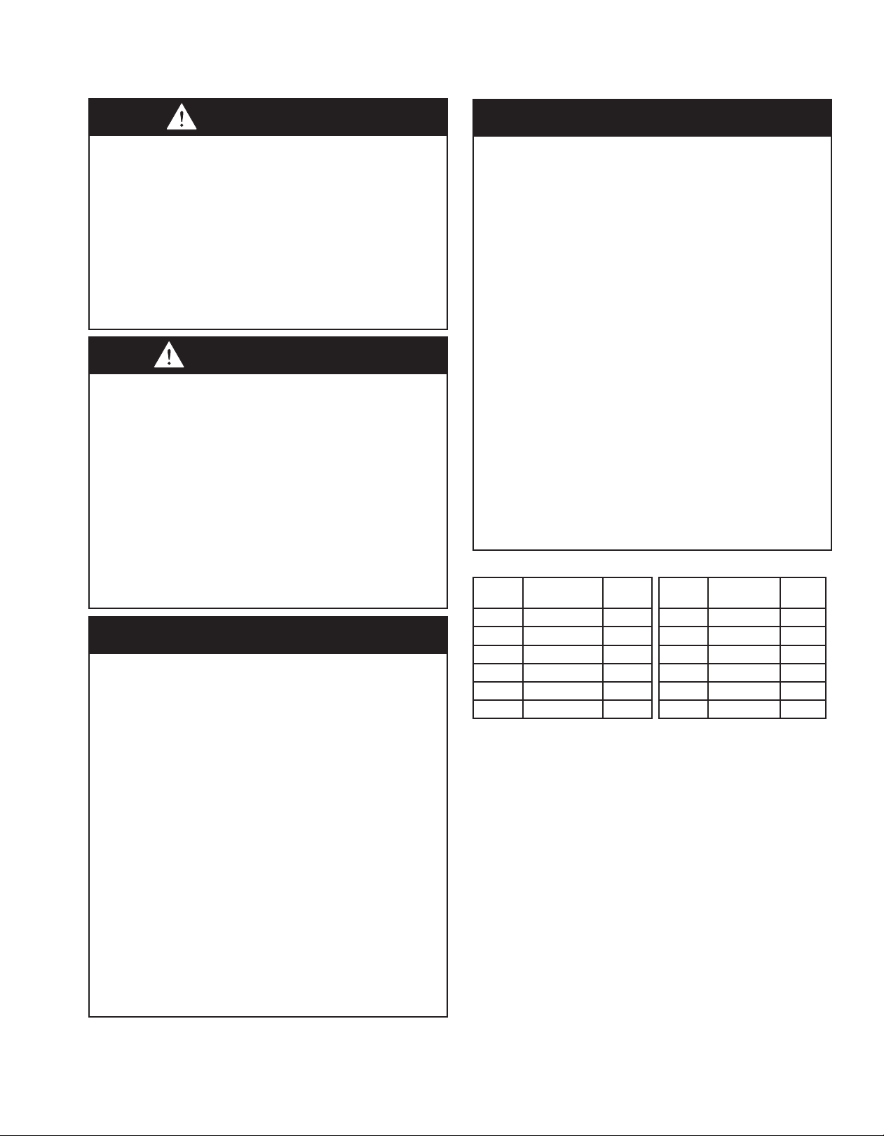
Figure 5.1 - SI (Metric) Conversion Factors
To
Convert Multiply By To
Obtain
To
Convert Multiply By To
Obtain
"W.C. 0.24 kPa CFH 1.699 m3/min
psig 6.893 kPa Btu/ft30.0374 mJ/m3
°F (°F-32) x 0.555 °C pound 0.453 kg
inches 25.4 mm Btu/hr 0.000293 kW
feet 0.305 meters gallons 3.785 liters
CFM 0.028 m3/min psig 27.7 "W.C.
SPECIAL DESIGN REQUESTS
Units are sometimes built with special features as requested by
the customer. This manual only covers standard features and does
not include any changes made for special feature requests by the
customer. Units built with special features are noted with a 5-digit
SPO (Special Product Order) Number on the Serial Plate.
STORAGE PRIOR TO INSTALLATION
If the unit is stored outside prior to installation, the unit should be
covered.

65-594.11
UNIT LOCATION
UNIT LOCATION
DANGER
Appliances must not be installed where they may be exposed
to a potentially explosive or ammable atmosphere.
DANGER
Les appareils ne doivent pas être installés à un endroit où ils
risquent d’être exposés à une atmosphère potentiellement
explosive ou inammable.
WARNING
To prevent premature heat exchanger failure, do not locate
ANY gas-red appliances in areas where corrosive vapors
(i.e. chlorinated, halogenated or acid) are present in the
atmosphere.
AVERTISSEMENT
Pour éviter la panne prématurée de l’échangeur thermique,
ne placez AUCUN appareil à gaz à des endroits où les
vapeurs corrosives (chlorées, halogénées ou acides) sont
présentes dans l’atmosphère.
IMPORTANT
1. Installation only in locations not accessible to the general
public.
2. Unit can be operated up to a maximum of 10,000 feet
(3048 m).
IMPORTANT
1. Pour installation uniquement dans des endroits non
accessibles au public.
2. L’unité peut être utilisée jusqu’à un maximum de 3048 m
(10,000 ft).
Location Recommendations
1. When locating the furnace, consider general space and
heating requirements, availability of gas and electrical
supply, and proximity to vent locations.
2. Unit must be installed on the positive pressure side of the
circulating blower.
3. Be sure the structural support at the unit location site is
adequate to support the weight of the unit. For proper
operation the unit must be installed in a level horizontal
position.
4. Do not install units in locations where the ue products
can be drawn into the adjacent building openings such
as windows, fresh air intakes, etc.
5. Be sure that the minimum clearances to combustible
materials and recommended service clearances are
maintained. Units are designed for installation on non-
combustible surfaces with the minimum clearances shown
in Figure 7.1 and Table 7.1
6. Units installed downstream of refrigeration systems, or
exposed to inlet air temperatures of 40°F or less, may
experience condensation, therefore, provisions should
be made for disposal of condensate. Means have been
provided in the bottom pan of the unit to accommodate a
condensate drain line connection ange.
7. When locating units, it is important to consider that the
combustion air and exhaust vent piping must be connected
to the outside atmosphere. The maximum equivalent
lengths are listed in Table 12.1.
8. In garages or other sections of aircraft hangars such as
oces and shops which communicate with areas used
for servicing or storage, keep the bottom of the unit at
least 7" above the oor. In public garages, the unit must
be installed in accordance with the Standard for Parking
Structures NFPA #88A and the Standard for Repair
Garages NFPA#88B. In Canada, installation of unit
heaters in airplane hangars must be in accordance with
the requirements of the enforcing authority, and in public
garages in accordance with the current CAN/CGA-B149
codes.
9. Do not install units in locations where gas ignition system is
exposed to water spray, rain, or dripping water.
10. All mechanical equipment generates some sound and
vibration that may require attenuation. Libraries, private
oces and hospital facilities will require more attenuation,
and in such cases, an acoustical consultant may be
retained to assist in the application. Locating the equipment
away from the critical area is desirable within ducting
limitations. Generally, a unit should be located within 15
feet of a primary support beam. Smaller deections mean
lesser vibration and noise transmission.

7
5-594.11
UNIT LOCATION / UNIT MOUNTING METHODS
Figure 7.1 - Combustible Material Clearances
1
A
TOP = 3"
BOTTOM = 1"
ACCESS
SIDE
NON-ACCESS
SIDE = 0"
Model Size Access Side (A)
100 thru 175 1" (2.54 cm)
200 thru 960 2" (5.08 cm)
jA 3'' minimum clearance to combustible material is required from the vent collar.
Table 7.1 - Recommended Service Clearances
Model Size Access Side Non-Access Side Top
100/125 20.0" (50.80cm)
6" (15.24cm) 10" (25.40cm)
150/175 25.0" (63.50cm)
200/225 27.0" (68.58cm)
250/300 30.0" (76.20cm)
350/400 41.0" (104.14cm)
500/600 30.0" (76.20cm)
700/800 41.0" (104.14cm)
840/960 41.0" (104.14cm)
Figure 7.2 - Dégagements de matériaux
combustibles
1
A
Dessus = 7.6 cm
Bas = 2.5 cm
Côté porte
d'accès
Côté opposé
à la porte
= 0 cm
Taille de
modèle
Côté porte
d'accès (A)
100 à 175 1" (2.54 cm)
200 à 960 2" (5.08 cm)
jUn dégagement minimal de 7,6 cm jusqu’au matériau combustible est requis à
partir du collet de ventilation..
Tableau 7.2 - Dégagements recommandés pour
l'entretien
Taille de
modèle
Côté porte
d'accès
Côté opposé à la
porte Dessus
100/125 20.0" (50.80cm)
6" (15.24cm) 10" (25.40cm)
150/175 25.0" (63.50cm)
200/225 27.0" (68.58cm)
250/300 30.0" (76.20cm)
350/400 41.0" (104.14cm)
500/600 30.0" (76.20cm)
700/800 41.0" (104.14cm)
840/960 41.0" (104.14cm)
UNIT MOUNTING METHODS
Determine the method of mounting that will be used. Be sure
the method of unit support (suspension or oor mounting) is
adequate to support the weight of the unit (see Weights for base
unit and factory installed option weights). For proper operation,
the unit must be installed in a level horizontal position.
Combustible material and service clearances as specied in
Figure 7.1 and Table 7.1 must be strictly maintained. To assure
that ames are directed into the center
of the heat exchanger tubes, the unit must be level in a
horizontal position.
Unit Suspension
Four 3/4" (1.90 cm) diameter suspension hanging locations
are provided in the base rail assembly of the unit. Refer to
Figure 52.1 for Suspension Hanging Locations and Figure 8.1
demonstrates how the unit should be suspended and fastened
to the unit base rail. If required, vibration isolators may be
added.
Suspension de l'appareil
Quatre emplacements de suspension de 1,9 cm (0.75") de
diamètre sont fournis dans l’assemblage du rail de base de
l’appareil. Reportez-vous à la Figure 52.1 pour connaître
les emplacements de suspension et la Figure 8.1 démontre
la façon dont l’appareil doit être suspendu et les tiges de
suspension xées au rail de base de l’appareil. Si nécessaire,
des isolateurs de vibration peuvent être ajoutés.

85-594.11
UNIT MOUNTING METHODS
Figure 8.1 - Unit Suspension Method
BLOWER
SECTION
DOOR
ELECTRICAL
SECTION
DOOR
HEATER
SERVICE
DOOR
(2) 3/4" NUTS &
LOCKWASHER
(1) 3/4" NUT &
LOCKWASHER
SUSPENSION
RODS
NOTE: SUSPENSION RODS,
LOCKWASHERS, AND NUTS
BY OTHERS
Figure 8.1 - Méthode de suspension de l’appareil
Porte de la
section de la
soufflante
Porte de la
section électrique
Porte de
service
du radiateur
(2) Écrou et rondelle de
1,9 cm (0.75")
(1) Écrou et rondelle de
1,9 cm (0.75")
tiges de
suspension
REMARQUE : tiges de suspension,
rondelles de blocage et écrou par des tiers
Floor Mounted Units
For oor installations, the oor structure must be adequately
designed to support the live weight load of the unit and any
other required support structure. Additional reinforcement should
be provided, if necessary. The oor should include threaded
5/8-inch anchor bolts spaced according to Figure 8.2 and
Table 9.1, for securing the unit in place. Anchor bolts should
extend at least 1.5" (3.81 cm) above the surface of the oor to
allow clearance for mounting washers, nuts and bolts (mounting
washers, nuts, and bolts by others).
Modèles installés sur le plancher
Pour les installations sur le plancher, la structure du toit doit être
correctement conçue pour soutenir la charge utile de l'appareil
et de toute autre structure de soutien requise. Au besoin, tout
renforcement supplémentaire devra être fourni. Le plancher
doit inclure des boulons d'ancrage letés de 5/8" (1.59cm)
espacés comme dans la Figure 8.2 and Tableau 9.1, pour xer
l'appareil en place. Les boulons d'ancrage doivent se prolonger
au-delà de la surface du plancher d’au moins 1,81 cm (1.5 inch)
pour permettre un dégagement susant pour la mise en place
des rondelles, des boulons et des écrous (par des tiers).
Figure 8.2 - Floor Mounted Unit Anchor Bolt
Locations
A
B5/8” Dia. (4)
C
Figure 8.2 - Emplacements des boulons d’ancrage
pour appareil installé sur le plancher
A
B1.59 cm Dia. (4)
C

9
5-594.11
UNIT MOUNTING METHODS
Table 9.1 - Floor Mounted Unit Anchor Bolt
Locations
Digit 2
Model
Size
Blower Type
(Digit 16) ABC
B
100/125 All 86.37"
(219.38cm)
36.36
(92.35cm) -
150/175 All 86.37"
(219.38cm)
40.61"
(103.15cm) -
200/225 All 86.37"
(219.38cm)
42.71"
(108.48cm) -
250/300 E,F,G, or H 86.27"
(219.13cm)
45.75"
(116.21cm) -
250/300 I, J, or K 112.12"
(284.78cm)
45.75"
(116.21cm) -
350/400 E, F, G, or H 86.27"
(219.13cm)
57.27"
(145.47cm) -
350/400 I, J, or K 122.2"
(310.39cm)
57.27"
(145.47cm) -
500/600 G or H 127.39"
(323.57cm)
45.75"
(116.21cm)
41.37"
(105.08cm)
500/600 I, J, or K 163.25"
(414.66cm)
45.75"
(116.21cm)
41.37"
(105.08cm)
700/800 G or H 127.39"
(323.57cm)
57.27"
(145.47cm)
41.37"
(105.08cm)
700/800 I, J, K, or L 163.25"
(414.66cm)
57.27"
(145.47cm)
41.37"
(105.08cm)
840/960 I, J, K, or L 204.39"
(519.15cm)
57.27"
(145.47cm)
82.50"
(209.55cm)
C
100/125 All 110.25"
(280.04cm)
36.36"
(92.35cm) -
150/175 All 110.25"
(280.04cm)
40.61"
(103.15cm) -
200/225 All 110.25"
(280.04cm)
42.71"
(108.48cm) -
250/300 E,F,G, or H 110.25"
(280.04cm)
45.75"
(116.21cm) -
250/300 I, J, or K 146.10"
(371.09cm)
45.75
(116.21cm) -
350/400 E, F, G, or H 110.25"
(280.04cm)
57.27"
(145.47cm) -
350/400 I, J, or K 146.10"
(371.09cm)
57.27"
(145.47cm) 0
Tableau 9.1 - Emplacements des boulons d’ancrage
pour appareil installé sur le plancher
2e
chire
Taille de
modèle
Type de
ventilateur
(16e chire)
ABC
B
100/125 All 86.37"
(219.38cm)
36.36
(92.35cm) -
150/175 All 86.37"
(219.38cm)
40.61"
(103.15cm) -
200/225 All 86.37"
(219.38cm)
42.71"
(108.48cm) -
250/300 E,F,G, or H 86.27"
(219.13cm)
45.75"
(116.21cm) -
250/300 I, J, or K 112.12"
(284.78cm)
45.75"
(116.21cm) -
350/400 E, F, G, or H 86.27"
(219.13cm)
57.27"
(145.47cm) -
350/400 I, J, or K 122.2"
(310.39cm)
57.27"
(145.47cm) -
500/600 G or H 127.39"
(323.57cm)
45.75"
(116.21cm)
41.37"
(105.08cm)
500/600 I, J, or K 163.25"
(414.66cm)
45.75"
(116.21cm)
41.37"
(105.08cm)
700/800 G or H 127.39"
(323.57cm)
57.27"
(145.47cm)
41.37"
(105.08cm)
700/800 I, J, K, or L 163.25"
(414.66cm)
57.27"
(145.47cm)
41.37"
(105.08cm)
840/960 I, J, K, or L 204.39"
(519.15cm)
57.27"
(145.47cm)
82.50"
(209.55cm)
C
100/125 All 110.25"
(280.04cm)
36.36"
(92.35cm) -
150/175 All 110.25"
(280.04cm)
40.61"
(103.15cm) -
200/225 All 110.25"
(280.04cm)
42.71"
(108.48cm) -
250/300 E,F,G, or H 110.25"
(280.04cm)
45.75"
(116.21cm) -
250/300 I, J, or K 146.10"
(371.09cm)
45.75
(116.21cm) -
350/400 E, F, G, or H 110.25"
(280.04cm)
57.27"
(145.47cm) -
350/400 I, J, or K 146.10"
(371.09cm)
57.27"
(145.47cm) 0

10 5-594.11
UNIT LIFTING
UNIT LIFTING
WARNING
Failure to follow proper lifting instructions and applicable
safety procedures could result in property damage, serious
injury, or death. Lifting should only be done by a qualied
rigging company. Use ALL lifting points. Test lift to ensure
proper balance and rigging.
AVERTISSEMENT
Le non-respect d’une bonne procédure de levage et des
procédures de sécurité qui s’appliquent pourrait mener à
des dommages matériels ou à des blessures graves, voire
mortelles. Le levage doit être eectué uniquement par une
entreprise spécialisée dans le gréage. Utilisez TOUS les
points de levage. Testez le levage pour assurer un bon
équilibre et un bon gréage.
Rigging and lifting of the units should only be done by a qualied
rigging company and follow appropriate industry standards,
including but not limited to the appropriate sections of ASME
B30, OSHA 1910, and OSHA 1926.
1. Follow site preparation instructions for overhead
suspension, oor mounting, equipment stand before
installation.
2. Check the Serial Plate(s) of unit with plans to be sure unit
is properly located. Although units may look outwardly
similar, their function, capacities, options, and accessories
will often vary.
3. Check unit dimensions of both the unit base and the
installation location where the unit will be installed.
4. The provisions for lifting are dependent on how the unit
was shipped:
a. All units with standard blower cabinets (Model Digit
16=A through H) are shipped fully crated with skid
supports below the unit. The unit may be lifted from
the bottom by means of a fork lift or other lifting device
only if the shipping support skids are left in place. DO
NOT attempt to lift the unit from the bottom unless the
shipping skid supports are still in place. When lifting
units, make sure the load is balanced.
b. All units with extended blower cabinets (Model Digit
16=I through L) are shipped without a crate and
cannot be lifted with a fork truck. Use a crane or other
overhead lifting device in conjunction with the lifting
holes for safe unit relocation (refer to the Dimensions
for base rail lifting hole locations). See the following
note #5. If the unit must be lifted from the bottom for
nal installation, be sure to properly support the unit
over its entire length to prevent damage.
5. When lifting the equipment with a crane, connect sturdy
steel cables, chains, or straps. For stability in lifting and
lowering and to prevent damage to the unit, include a
spreader bar. Avoid twisting or uneven lifting of the unit.
Test lift the unit to check for proper rigging balance before
hoisting to the desired installation location.
6. Position the unit to its ductwork or where ductwork will be
located and suspend or oor mount the unit. For proper
operation, the unit must be installed in a level horizontal
position. Use a spirit level to ensure that the unit is
suspended or oor mounted correctly.
7. Refer to the applicable sections to make Venting, Gas
Connections, Electrical Connections, and Cooling Coil
Connections. Make nal unit connections to the electric
power supply and remote control circuits. Caulk all utility
line clearance holes on the unit after connections are
completed.
8. Refer to the applicable sections to make nal unit
connections for venting, gas and electrical utility connec-
tions, control wiring, and cooling system connections if
equipped. Caulk all utility line clearance holes on the unit
after connections are completed.

11
5-594.11
DUCT CONNECTIONS / UTILITY CONNECTIONS
DUCT CONNECTIONS
1. The furnace discharge (units with Model Digit 2=B) is
designed to accept straight ductwork (see Figure 11.1).
The blower section end and bottom openings (all units) and
cooling cabinet section discharge (units with Model Digit
2=C) are designed to accept 90° anged ductwork (see
Figure 11.2).
Provide an airtight seal between the ductwork and the
furnace. Seams with cracks in the ductwork should be
caulked and/or taped and be of permanent type. All duct
connections MUST be airtight to prevent air leakage.
2. Provide uniform air distribution over the heat exchanger.
Use turning vanes where required to obtain uniform air
distribution. (See Figure 11.3).
3. Provide removable access panels on the downstream side
of the ductwork. (See Figure 11.1.) This opening should
be large enough to view smoke or reect light inside the
casing
Figure 11.1 - Furnace Discharge Duct Connection
STRAIGHT
DUCTWORK
DUCT FURNACE
ACCESS
PANEL
DUCTWORK
Figure 11.2 - Blower Section Inlet and Cooling Coil
Section Discharge Duct Connections
DUCTWORK
90°
FLANGED
DUCTWORK
BLOWER AND/OR
COOLING COIL
CABINET
Figure 11.3 - Recommended Field Installed Dis-
charge Duct Congurations for Blower Package Units
DIMENSION “B” SHOULD NEVER
BE LESS THAN 1/2 OF DIMENSION “A”
PROVIDE LEAK TIGHT ACCESS
PANELS IN DISCHARGE DUCT
FOR HEAT EXCHANGER INSPECTION.
PROVIDE LEAK TIGHT ACCESS
PANELS IN DISCHARGE DUCT
FOR HEAT EXCHANGER INSPECTION.
TURNING
VANES
(3” MAX)
TURNING
VANES
(3” MAX)
UTILITY CONNECTIONS
Utility and control connections can be made to the unit from the
bottom or through the xed side panels for oor mounted units.
Holes can be made in xed side panels to accommodate utility
connections for any model or as specied according to the unit
dimensional drawings. Sealing of holes cut in the unit casing for
utility connections should be done with care to prevent air leaks.
1/2"

12 5-594.11
INSTALLATION - VENTING
UNIT INSTALLATION
Refer to the applicable sections to make Venting, Gas
Connections, Electrical Connections, and Cooling Coil
Connections. Make nal unit connections to the electric power
supply and remote control circuits. Caulk all utility line clearance
holes on the unit after connections are completed.
Venting
WARNING
1. Gas red heating equipment must be vented - do not
operate unvented.
2. A built-in power exhauster is provided - additional external
power exhausters are not required or permitted.
3. If you are replacing an existing heater, it may be necessary
to resize the venting systems. Improperly sized venting
systems can result in vent gas leakage or the formation of
condensate. Refer to the National Fuel Gas Code ANSI
Z223.1 or CSA B149.1 latest edition. Failure to follow these
instructions can result in serious injury or death.
4. Under no circumstances should two sections of double
wall vent pipe be joined together within one horizontal vent
system due to the inability to verify complete seal of inner
pipes.
AVERTISSEMENT
1. Les équipements de chauage au gaz doivent avoir un
système de ventilation – ne les faites pas fonctionner sans
évacuation des gaz.
2. Les unités sont munies d’un extracteur électrique intégré
– des extracteurs électriques externes supplémentaires ne
sont pas requis ni permis.
3. Si vous remplacez un appareil de chauage existant, vous
aurez peut-être à modier les systèmes de ventilation. Des
systèmes de ventilation de diamètre insusant peuvent
causer des fuites de gaz ou la formation de condensat.
Reportez-vous au code National Fuel Gas ANSI Z223.1 ou
à la dernière édition de la norme CSA B149.1. Le non-
respect de ces directives pourrait entraîner des blessures
graves, voire mortelles.
4. Il est interdit d’accoupler deux longueurs de tuyau à double
paroi dans une même installation d’évacuation horizontale
étant donné l’impossibilité de vérier l’étanchéité des
raccords du tuyau intérieur.
CAUTION
Installation must conform with local building codes or in the
absence of local codes, with Part 7, Venting of Equipment, of
the National Fuel Gas Code, ANSI Z223.1 (NFPA 54) - latest
edition. In Canada installation must be in accordance with
CSA B149.1.
ATTENTION
L'installation doit se faire conformément aux codes locaux
de la construction ou, à défaut de tels codes, conformément
à la Partie 7 « Venting of Equipment » du National Fuel Gas
Code, ANSI Z223.1 (NFPA 54) – dernière édition. Au Canada,
l'installation doit se faire conformément à la norme CSA
B149.1.
The separated combustion duct furnaces must be vented with
the proper passageway as described in these instructions to
convey ue gases from the unit or the vent connector to the
outside atmosphere. The heaters must also have a separate
combustion air intake pipe to bring in fresh air for combustion
from the outside atmosphere.
The venting instructions are organized in sections, based on
installation type. The sections are identied as follows:
Section Installation Instructions by Vent System Type
AGeneral Instructions for ALL installations
BVERTICAL 2-PIPE Vent Systems j
CHORIZONTAL 2-PIPE Vent Systems j
DHORIZONTAL AND VERTICAL CONCENTRIC
Vent Systems j
j The differences between Vertical and Horizontal vent systems in 2-Pipe
or Concentric Vent configurations will be identified in “Section A - General
Instructions – All Units”.
Section A - General Instructions - All Units
A1. If the heater being installed is replacing existing
equipment and using the existing vent system from that
equipment, inspect the venting system for proper size
and horizontal pitch, as required in the National Fuel Gas
Code ANSI Z223.1 or CSA B149.1 Installation Code-latest
edition and these instructions. Determine that there is
no blockage or restriction, leakage, corrosion and other
deciencies, which could cause an unsafe condition.
A2. The combustion air and vent pipes should be galvanized
steel or other suitable corrosion resistant material. Follow
the National Fuel Gas Code for minimum thickness of
vent material. The minimum thickness for connectors
varies depending on the pipe diameter. Do not vent unit
with PVC or other forms of plastic venting material.
A3. All heaters come with factory installed vent and
combustion air adapters for attaching the pipe to the
heater. The pipe diameters are 4" for model sizes
100-175 and 6" for model sizes 200-400. All units are
classied as Category III vented appliances, which
dened by ANSI is positive pressure, non-condensing,
and requires the vent system to be gastight. Attach the
vent pipe to the adapter with 3 corrosion resistant screws.
(Drill pilot holes through the vent pipe and adapter prior
to screwing in place). Vent pipe must not be smaller than
the connector size. Category III vent systems listed by a
nationally recognized agency and matching the diameters
specied may be used. Dierent brands of vent materials
may not be intermixed.
A4. Limit the total equivalent vent pipe length to a minimum
of 5' and a maximum as shown in Table 12.1, making the
vent system as straight as possible. Total equivalent vent
pipe length must include elbows. The equivalent length of
a 4" elbow is 5' and for a 6" elbow is 7
Table 12.1 - Individual Total Equivalent Lengths for
Combustion Air and Exhaust Vent Pipes
Model Size Minimum (ft) Maximum (ft)
100, 125, 150, 175 5 55
200, 225 5 70
250, 300 5 63
350, 400 5 70

13
5-594.11
INSTALLATION - VENTING
A5. A minimum of 12" straight pipe is recommended from the
ue outlet before turns in the vent pipe.
A6. air pipes are to be installed with a minimum downward
slope from the appliance of 1/4 inch per foot and
suspended securely from overhead structures at points
not greater than 3' apart.
A7. Fasten individual lengths of vent together with at least
three corrosion resistant sheet metal screws.
A8. Keep single wall vent pipe at least 6" from combustible
materials. For double wall vent pipe, follow the vent
pipe manufacturer’s clearances to combustibles. The
minimum distance from combustible materials is based
on the combustible material surface not exceeding 160°F.
Clearance from the vent pipe (or the top of the unit)
may be required to be greater than 6" if heat damage
other than re could result (such as material distortion or
discoloration).
A9. Avoid venting through unheated space when possible.
When venting does pass through an unheated space or
if the unit is installed in an environment that promotes
condensation, insulate runs greater than 5' to minimize
condensation. Inspect for leakage prior to insulating and
use insulation that is noncombustible with a rating of not
less than 400°F. Install a tee tting at the low point of the
vent system and provide a drip leg with a clean out cap as
shown in Figure 15.2.
A10. When the vent passes through a combustible INTERIOR
wall or oor, a metal thimble 4" greater than the vent
diameter is necessary. If there is 6' or more of vent pipe
in the open space between the appliance and where the
vent pipe passes through the wall or oor, the thimble
need only be 2" greater than the diameter of the vent
pipe. If a thimble is not used, all combustible material
must be cut away to provide 6" of clearance. Where
authorities have jurisdiction type B vent may be used
for the last section of vent pipe to maintain clearance to
combustibles while passing through wall or oor. See
Figure 13.1. Any material used to close the opening must
be noncombustible.
Figure 13.1 - Venting Through Combustible Roof or
Wall
Horizontal Venting Vertical Venting
ROOF
FLASHING
LISTED
THIMBLE SINGLE WALL
PIPE
LISTED
CAP
ROOF
FLASHING
CLEARANCE
SPECIFIED BY
TYPE B VENT
MANUFACTURER
DOUBLE WALL
PIPE
LISTED
CAP
SINGLE WALL
PIPE
LISTED
THIMBLE
SINGLE WALL
PIPE
MODINE
SPECIFIED
CAP
CLEARANCE
SPECIFIED BY
TYPE B VENT
MANUFACTURER
SINGLE WALL
PIPE
MODINE
SPECIFIED
CAP
DOUBLE WALL
PIPE
j See Instruction A12 for attaching single wall pipe to double wall pipe
A11. All seams and joints of un-gasketed single wall pipe
must be sealed with metallic tape (3M aluminum foil
tapes 433 or 363 are acceptable) or silastic suitable for
temperatures up to 400°F. Wrap the tape two full turns
around the vent pipe. One continuous section of double
wall vent pipe may be used within the vent system. Refer
to instruction A12 in “Section A – General Instructions –
All Units” for attaching double wall pipe to single wall pipe.
A12. The following are General Instructions for Double
Wall (Type B) Terminal Pipe Installation. Under no
circumstances should two sections of double wall vent
pipe be joined together within one horizontal vent system
due to the inability to verify complete seal of inner pipes.
How to attach a single wall vent terminal to double
wall (type B) vent pipe:
1. Look for the “ow” arrow on the vent pipe.
2. Slide the vent terminal inside the exhaust end of the double
wall vent pipe.
3. Drill (3) holes through the pipe and the vent terminal. Using
3/4" long sheet metal screws, attach the cap to the pipe. Do
not over tighten.
How to connect a single wall vent system to a
double wall (type B) vent pipe:
1. Slide the single wall pipe inside the inner wall of the double
wall pipe.
2. Drill (3) holes through both walls of the single and double
wall vent pipes. Using 3/4" sheet metal screws, attach the
two pieces of pipe. Do not over tighten.
3. The gap between the single and double wall pipe must be
sealed but it is not necessary to ll the full volume of the
annular area. To seal, run a large bead of 400°F silastic
around the gap.
A13. Do NOT vent this appliance into a masonry chimney.
A14. Do NOT use dampers or other devices in the vent or
combustion air pipes.
A15. The venting system must be exclusive to a single
appliance, and no other appliance is allowed to be vented
into it.
A16. Precautions must be taken to prevent degradation of
building materials by ue products.
A17. Single wall vent pipe must not pass through any
unoccupied attic, inside wall, concealed space, or oor.
A18. Uninsulated single wall vent pipe must not be used
outdoors for venting appliances in regions where the 99%
winter design temperature is below 32°F.
A19. Long runs of horizontal or vertical combustion air pipes
may require insulation in very cold climates to prevent the
buildup of condensation on the outside of the pipe where
the pipe passes through conditioned spaces.
A20. Vent termination clearances must be maintained:

14 5-594.11
INSTALLATION - VENTING
Table 14.1 - Vent Termination Clearances
Structure Minimum Clearances for Vent
Terminal Location
Forced air inlet within 10 feet 3 feet above
Combustion air inlet of another
appliance
6 feet all directions
Door, window, gravity air inlet, or any
building opening
4 feet horizontal and below 1 foot
above
Electric meter, gas meter, gas
regulator, and relief equipment j
4 feet horizontal (U.S.)
6 feet horizontal (Canada)
Gas regulator j3 feet horizontal (U.S.)
6 feet horizontal (Canada)
Adjoining building or parapet wall 6 feet all directions
Adjacent public walkways 7 feet all directions
Grade (ground level) 3 feet above k
jDo not terminate the vent directly above a gas meter or regulator.
kThe vent must be at least 6" higher than anticipated snow depth.
A21. Vertical combustion air pipes should be tted with a tee
with a drip leg and a clean out cap to prevent against the
possibility of any moisture in the combustion air pipe from
entering the unit. The drip leg should be inspected and
cleaned out periodically during the heating season.
A22. In addition to following these General Instructions, specic
instructions for Vertical and Horizontal vent systems in
2-Pipe or Concentric Vent congurations must also be
followed. The following outlines the dierences:
Vertical Vent System Determination
• Vertical vent systems terminate vertically (up) (an example is
shown in Figure 14.1).
• Determine the venting conguration as follows:
• For two building penetrations through the wall or roof
(one for the combustion air inlet pipe and one for the
vent pipe), proceed to “Section B - Vertical 2-Pipe
Venting”.
• For a single larger building penetration through the wall
or roof, through which both the combustion air inlet and
vent pipes will pass, proceed to “Section D - Horizontal
and Vertical Concentric Venting”.
• For all other cases, proceed to the next section for
Horizontal Vent System Determination.
Horizontal Vent System Determination
• Horizontal vent systems terminate horizontally (sideways) (an
example is shown in Figure 15.2).
• Determine the venting conguration as follows:
• For two building penetrations through the wall or roof
(one for the combustion air inlet pipe and one for the
vent pipe), proceed to “Section C - Horizontal 2-Pipe
Venting”.
• For a single larger building penetration through the wall
or roof, through which both the combustion air inlet and
vent pipes will pass, proceed to “Section D - Horizontal
and Vertical Concentric Venting”.
Section B - Vertical 2-Pipe Vent System
Installation
B1. This section applies to vertically vented 2-pipe (one
combustion air inlet pipe and one vent pipe) vent systems
and is in addition to “Section A - General Instructions - All
Units”.
B2. Vertical vent systems terminate vertically (up).
B3. It is recommended to install a tee with drip leg and clean
out cap as shown in Figure 14.1.
B4. The combustion air and vent terminals must be Modine
part number:
• 5H072285-0001 (Item Code 27866) for 4" vent pipe
• 5H072285-0002 (Item Code 27868) for 6" vent pipe
B5. Vertical vents must terminate a minimum horizontal and
vertical distance from roof lines and adjacent walls or
obstructions. These minimum distances are outlined in
Figure 14.1 and Table 14.2.
B6. The vent must terminate at least 1 foot above and 16
inches horizontally from the combustion air inlet.
B7. Once venting is complete, proceed to section titled
“Installation - Gas Connections”.
Figure 14.1 - Vertical Venting - 2 Pipes Sloped Roof
“H” FEET
MINIMUM PER
TABLE 14.2
ROOF PITCH IS:
X / 12
“H” FEET
MINIMUM PER
TABLE 14.2
TEE WITH
DRIP LEG AND
CLEANOUT CAP
10 FEET OR LESS
TO ROOF PEAK
EXHAUST
COMBUSTION AIR
MAINTAIN MINIMUM
CLEARANCE TO
COMBUSTIBLES
12"
MINIMUM
USE LISTED
THIMBLES
THROUGH ROOF
AND CEILINGS
ROOF
FLASHING
LISTED VENT
TERMINAL
LISTED AIR
INLET TERMINAL
2 FEET MINIMUM
X
12"
16" MINIMUM
Table 14.2 - Minimum Height from Roof to Lowest
Discharge Opening
Roof Rise
“X” (in)
Equivalent
Roof Pitch
Minimum Height
“H” (ft) j
0-10 Flat to 10/12 3.00
10-12 10/12 to 12/12 4.00
12-14 12/12 to 14/12 5.00
14-16 14/12 to 16/12 6.00
16-18 16/12 to 18/12 7.00
18-21 18/12 to 21/12 8.00
jIncrease "H" as required to accommodate snow depth.

15
5-594.11
INSTALLATION - VENTING
Figure 15.1 - Vertical Venting - 2 Pipes Flat Roof
LISTED VENT
DISTANCE “D” TO
WALL OR ADJOINING
BUILDNG
MAINTAIN MINIMUM
CLEARANCE TO
COMBUSTIBLES
*SIZE ACCORDING
TO EXPECTED
SNOW DEPTH
“H” FEET MINIMUM
ABOVE WALL OR
ADJOINING
BUILDING PER
TABLE 15.1
TERMINAL
ROOF
FLASHING
EXHAUST
COMBUSTION AIR
USE LISTED
THIMBLE
THROUGH
CEILING
TEE WITH
DRIP LEG AND
CLEANOUT CAP
LISTED AIR
INLET TERMINAL
3 FEET
MINIMUM*
12"
MINIMUM
12"
MINIMUM
Table 15.1 - Minimum Height Above Adjacent Wall
Less than 10 Feet Away
"D" "H"
10 Feet or Less 2 Feet Minimum
Greater than 10 Feet No Additional Height Required
Section C - Horizontal 2-Pipe Vent
Installation
C1. This section applies to horizontally vented 2-pipe vent
systems (one combustion air inlet pipe and one vent pipe)
and is in addition to “Section A - General Instructions - All
Units”.
C2. Horizontal vent systems terminate horizontally (sideways).
C3. Horizontal vents must be terminated with a Modine p/n:
• 5H072285-0001 (Item Code 27866) for 4" vent pipe
• 5H072285-0002 (Item Code 27868) for 6" vent pipe
The cap must terminate a minimum distance from the external
wall, as summarized in Figure 15.2.
C4. The termination of horizontally vented system must
extend 12 inches beyond the exterior surface of an
exterior wall.
C5. The combustion air pipe must be a minimum of 16 inches
below the vent pipe, and 24 inches from the exterior wall.
C6. Construct the vent system as shown in Figure 15.2.
Figure 15.2 - Horizontal 2-Pipe Venting
COMBUSTION AIR
EXHAUST
24'' MIN.
24'' MIN.
12''
16'' MIN.
SUPPORT BRACKET
(See Fig. 15.3 for detail)
SUPPORT BRACKET
(See Fig.15.3 for detail)
TERMINAL
TERMINAL
ADJACENT
BUILDING
TEE WITH DRIP
LEG AND
CLEANOUT CAP
AT LOW POINT
OF VENT SYSTEM
PITCH VENT PIPE DOWNWARD
FROM APPLIANCE 1/4" PER FOOT
PITCH COMBUSTION AIR
PIPE DOWNWARD FROM
APPLIANCE 1/4" PER FOOT
MUST USE THIMBLE
THROUGH WALL
C7. When horizontal vents pass through a combustible
wall (up to 8 inches thick), the vent passage must be
constructed and insulated as shown in Figure 15.3.
C8. The vent must be supported as shown in Figure 15.3.
C9. When condensation may be a problem, the vent system
shall not terminate over public walkways or over an area
where condensate or vapor could create a nuisance
or hazard or could be detrimental to the operation of
regulators, relief openings, or other equipment.
Figure 15.3 - Exhaust Vent Construction Through
Combustible Walls and Support Bracket
C10. Maintain a 1/4" per foot downward slope away from
the heater and place a drip leg with clean out near the
exit of the vent as shown in Figure 15.2, or allow the
condensate to drip out the end.
C11. For a vent termination located under an eave, the
distance of the overhang must not exceed 24". The
clearance to combustibles above the exterior vent must
be maintained at a minimum of 12". Consult the National
Fuel Gas Code for additional requirements for eaves that
have ventilation openings.
C12. Once complete, proceed to section titled “Installation -
Gas Connections”.
Section D - Concentric Vent System
Installation
WARNING
The concentric vent adapter box must be installed inside of
the structure or building. Do not install this box on the exterior
of a building or structure.
AVERTISSEMENT
La boîte adaptatrice concentrique doit être installée à
l'intérieur de la structure ou du bâtiment. Elle n'est pas
conçue pour être installée à l'extérieur d’un bâtiment ou d’une
structure.
D1. This section applies to both horizontally and vertically
vented concentric vent systems as dened in “Section A –
General Instructions – All Units”, and is in addition to the
instructions in that section.
D2. When utilizing the concentric vent option, it should
have been predetermined whether the appliance will be
horizontally or vertically vented. Before proceeding, verify
that the concentric vent kit received contains the correct
components for the installation:

16 5-594.11
INSTALLATION - VENTING
For Vertically Vented Units (Refer to Figure 16.1):
Model Size (Digits 4-6) 100-175 200-400
Kit Part Number 33356
(3H0349290003)
33357
(3H0349290004)
Kit Contents Part Number Part Number
Concentric Vent Adapter Box 3H0373840004 3H0373840005
Outlet Vent Termination Cap 5H0722850001 5H0722850002
Combustion Air Inlet Terminal 5H0751540004 5H0751540006
Figure 16.1 -
Vertical Concentric Vent Kit Components
Combustion Air
Inlet Terminal
Outlet Vent
Termination Cap
Building
Roof / Ceiling
Concentric
Vent Adapter
Box
Combustion Air Exhaust
6"Min.
12" Min.* *Size according
to expected
snow depth.
For Horizontally Vented Units (Refer to Figure 16.2):
Model Size (Digits 4-6) 100-175 200-400
Kit Part Number 32161
(3H0349300003)
32162
(3H0349300004)
Kit Contents Part Number Part Number
Concentric Vent Adapter Box 3H0373840004 3H0373840005
Outlet Vent Termination Cap 5H0751500001 5H0751500002
Combustion Air Inlet Guard 3H0349320004 3H0349320006
Figure 16.2 -
Horizontal Concentric Vent Kit Components
Building Side Wall
Outlet Vent
Termination Cap
Combustion Air
Intake Guard
14" Min.
1" Min.
Concentric
Vent Adapter
Box
D3. Once the kit contents have been veried as correct for the
direction of venting, the concentric vent adapter box is to
be installed. Determine the location of the box. Be sure to
maintain all clearances as listed in these instructions.
D4. The adapter box is to be mounted on the interior side of
the building. It must not be mounted outside the building.
The adapter box has integral mounting holes for ease
of installation. When horizontal venting multiple units,
the minimum spacing between any sides of the adapter
boxes must be 18" and boxes must not overlap in the
vertical plane (above or below). When condensation
may be a problem, the vent system shall not terminate
over public walkways or over an area where condensate
or vapor could create a nuisance or hazard or could be
detrimental to the operation of regulators, relief openings,
or other equipment.
D5. The adapter box can be mounted ush to the wall (for
horizontal kits) or to the ceiling (for vertical kits). The box
can also be oset from the wall or ceiling by using eld
supplied brackets. When mounting the box, consider
serviceability and access to the vent and combustion air
pipes. If the box is to be mounted using eld supplied
brackets, these brackets must be strong enough to rigidly
secure the box to the wall or ceiling, and should be made
from corrosion resistant material.
D6. Determine the length of the vent pipe and combustion
air inlet pipe for the selected location. THE VENT PIPE
WILL PASS THROUGH THE CONCENTRIC VENT BOX.
THE LAST SECTION OF VENT PIPE IS A CONTINUOUS
LENGTH OF DOUBLE WALL “B” VENT. See section A12
for attaching and terminating double wall pipe. Begin with
pipe lengths on the concentric pipe side of the adapter
box referring to Figure 17.1. These pipes will extend
through the building wall or roof as well as any added
length for the thickness of the wall and the oset from any
eld installed brackets.
For Vertical Concentric Vent Kits
(refer to Figure 16.1):
• The bottom of the combustion air intake pipe must
terminate above the snow line, or at least 12 inches
above the roof, whichever distance is greater.
• The bottom of the vent cap must terminate at least 6
inches above the top of the combustion air intake cap.
For Horizontal Concentric Vent Kits
(refer to Figure 16.2):
• The combustion air intake pipe must terminate at least
1 inch from the wall to prevent water from running down
the wall and into the pipe.
• The back of the vent cap must terminate at least 14
inches from the combustion air intake pipe.
D7. Cut the concentric side vent and combustion air pipes
to the proper length as determined in the previous step.
Note that the vent pipe diameter is 4" and the combustion
air intake pipe diameter is 6" for model sizes 100-175,
and 6” and 8” respectively for model sizes 200-400. The
pipes must be single wall galvanized or stainless steel
material, except for the last section of vent pipe, which
must be one continuous length of double wall B-vent
extended through the concentric vent box and combustion
air inlet pipe on the concentric side of the box.
D8. Allow the concentric side vent pipe to pass through the
concentric vent adapter box, as shown in Figure 17.1.
Attach the double wall vent pipe to the single wall vent
pipe that goes to the unit. Be sure to seal the joint and
the open area around the double wall vent. Seal all joints
and seams using sealant suitable for temperatures up to
400°F.
D9. Slide the combustion air pipe over the vent pipe and
attach to the air inlet of the concentric adapter box, as
shown in Figure 17.1, using at least 3 corrosion resistant
sheet metal screws. Seal the joint and seam using
sealant suitable for temperatures up to 400°F.

17
5-594.11
INSTALLATION - VENTING
D10. Place this assembly (the adapter box, vent pipe and
combustion air pipe) through the wall or roof and verify
that the distance requirements as dened in Step D7 are
met. Securely attach the assembly building.
D11. From outside the building, caulk the gap between the
combustion air intake pipe and the building penetration.
D12. Attach the combustion air intake and vent pipe
terminations as follows:
Figure 17.1 - Adapter Box with Combustion Air
Intake Pipe Attached
Outlet Vent
Pipe Extended
Through Box
Combustion Air
Pipe Attached
AB
4.57”
Model Sizes A B
100-175 13.33" 18.84"
200-400 17.00" 15.27"
For Vertical Concentric Vent Kits
(refer to Figure 16.1):
• Slide the combustion air cap down over the vent pipe
and fasten it to the combustion air pipe with at least 3
corrosion resistant sheet metal screws.
• Attach the vent cap to the vent pipe using at least
3 corrosion resistant sheet metal screws. Refer to
instruction A12 for connecting terminal to double wall
pipe.
• Caulk the gap between the combustion air cap and the
vent pipe with silicone sealant, or other appropriate
sealants suitable for metal to metal contact and for
temperatures up to 400° F.
For Horizontal Concentric Vent Kits
(refer to Figure 16.2):
• Attach the combustion air intake guard using corrosion
resistant screws at the end of the combustion air intake
pipe to prevent animals and debris from entering.
• Attach the vent cap to the vent pipe using at least 3
corrosion resistant sheet metal screws.
D13. Install vent pipe and combustion air pipe between unit
heater and concentric vent adapter box as outlined in
“Section A – General Instructions – All Units”.
D14. Once venting is complete, proceed to the section titled
“Installation - Gas Connections”.

18 5-594.11
INSTALLATION - GAS CONNECTIONS
Gas Connections
WARNING
1. All eld gas piping must be pressure/leak tested prior to
operation. Never use an open ame. Use a soap solution
or equivalent for testing.
2. Gas pressure to appliance controls must never exceed
3.4 kPa (14"W.C. or 1/2 psi)
3. To reduce the opportunity for condensation, the minimum
sea level input to the appliance, as indicated on the serial
plate, must not be less than 5% below the rated input, or
5% below the minimum rated input of dual rated units.
AVERTISSEMENT
1. Toutes les canalisations de gaz sur site doivent être
testées (pression/fuites) avant usage. Ne recherchez
jamais les fuites avec une amme nue. Utilisez plutôt de
l’eau savonneuse ou un produit équivalent.
2. La pression de gaz aux commandes de l’appareil ne doit
jamais dépasser 3.4 kPa (35,5 cm C.E. ou 1/2 psi).
3. Pour réduire le risque de condensation, l’entrée minimum
dans l’appareil au niveau de la mer, telle qu’indiquée sur la
plaque de série, ne doit pas être moins de 5 % inférieure à
la valeur d’entrée nominale des appareils à double valeur
nominale.
CAUTION
Purging of air from gas supply line should be performed as
described in ANSI Z223.1 - latest edition “National Fuel Gas
Code”, or in Canada in CAN/CGA-B149 codes.
ATTENTION
La purge de l’air des tuyauteries de gaz doit se faire selon la
procédure ANSI Z223.1 de la dernière édition du « National
Fuel Gas Code » ou des codes CAN/CGA-B149 du Canada.
IMPORTANT
To prevent premature heat exchanger failure, the input to the
appliance, as indicated on the serial plate, must not exceed
the rated input by more than 5%.
IMPORTANT
Pour éviter une défaillance prématurée de l’échangeur de
chaleur, le pouvoir calorique du gaz utilisé ne doit pas
excéder de plus de 5 % la valeur nominale inscrite sur la
plaque signalétique de l’appareil.
1. Installation of piping must conform with local building
codes, or in the absence of local codes, with the National
Fuel Gas Code, ANSI Z223.1 (NFPA 54) - Latest Edition.
In Canada, installation must be in accordance with CAN/
CGA-B149.1 for natural gas units and CAN/CGA-B149.2
for propane units.
2. Piping to units should conform with local and national
requirements for type and volume of gas handled, and
pressure drop allowed in the line.
3. Refer to Model Digits 4-6 of the Model Nomenclature
on page 63 and the value on the unit Model ID plate
(not individual furnace serial plates) to determine the gas
heating capacity in Thousands of Btu/hr (MBH). The
Model ID plate is located on the blower section electrical
compartment door. See Figure 18.1 for an example Model
ID plate.
Figure 18.1 - Model ID Plate Example
4. For the length of pipe necessary, determine the pipe
diameter from Table 19.1 or Table 19.2 for the unit heating
capacity. Where several units are served by the same main,
the total capacity and length of main must be considered.
While the gas connection(s) on the unit may be smaller
than the required supply pipe diameter, do not use pipe
sizes smaller than what is required leading up to the unit.
At the unit, reduce the pipe size down to the appropriate
size (sizes 100-225 are 1/2" connections, 250-960 are 3/4"
connections). Avoid pipe sizes smaller than 1/2". The inlet
pressure to the unit must be 6-7" W.C. for natural gas and
11-14" W.C. for propane gas. When sizing the inlet gas
pipe diameter, be sure the unit supply pressure can be met
after the line pressure drop has been subtracted. If the line
pressure drop is too high, refer to NFPA 54 National Fuel
Gas Code for other gas pipe capacities.
5. The gas piping to the unit can enter the unit from the side
of the unit or from below. Install a ground joint union with
brass seat and a manual shut-o valve external of the
unit casing, and adjacent to the unit for emergency shut-
o and easy servicing of controls, including a 1/8" NPT
plugged tapping accessible for test gauge connection (See
Figure 18.2). Verify the manual shut-o valve is gas tight
on an annual basis.
6. Provide a sediment trap before each unit in the line where
low spots cannot be avoided. (See Figure 18.2).
Figure 18.2 -
Recommended Sediment Trap/Manual Shut-o Valve
Installation - Side or Bottom Gas Connection
GAS
SUPPLY LINE
GAS
SUPPLY LINE
GROUND
JOINT
UNION
W/ BRASS
SEAT
MANUAL GAS
SHUT-OFF VALVE
3"
MIN.
SEDIMENT
TRAP
PLUGGED
1/8" NPT TEST
GAGE CONNECTION
TO
CONTROLS
j
j Manual shut-off valve is in the “OFF” position
when handle is perpendicular to pipe.
7. When Pressure/Leak testing, pressures above 14" W.C.
(1/2 psi), close the eld installed shut-o valve, disconnect
the appliance and its combination gas control from the gas
supply line, and plug the supply line before testing. When
testing pressures 14" W.C. (1/2 psi) or below, close the
manual shut-o valve on the appliance before testing.

19
5-594.11
INSTALLATION - GAS CONNECTIONS
Table 19.1 - Gas Pipe Capacities - Natural Gas j
Pipe
Length (ft)
Capacity in MBH by Nominal Pipe Diameter
1∕2” 3∕4” 1” 1 1∕4” 1 1∕2” 2” 2 1∕2” 3”
10 138 287 540 1,113 1,659 3,203 5,103 9,009
20 95 197 371 762 1,145 2,195 3,507 6,195
30 76 159 298 612 917 1,764 2,814 4,977
40 65 135 255 524 784 1,512 2,405 4,253
50 58 120 226 464 695 1,344 2,132 3,770
60 53 109 205 420 630 1,218 1,932 3,423
70 48 100 188 386 580 1,113 1,775 3,150
80 44 93 175 360 540 1,038 1,659 2,930
90 42 87 165 338 506 974 1,554 2,741
100 40 83 155 319 478 921 1,470 2,594
125 35 74 138 282 423 816 1,302 2,300
150 32 66 125 256 384 739 1,176 2,079
175 29 61 114 235 353 680 1,082 1,911
200 27 57 107 219 329 632 1,008 1,785
250 24 50 95 194 291 561 894 1,575
j Gas pipe capacities based on Table 19.1.1(a) of NFPA 54 for schedule 40
metallic pipe with inlet pressure less than 2 psi, with a pressure drop of 0.3" w.c.
and gas specific gravity of 0.60.
Table 19.2 - Gas Pipe Capacities - Propane Gas k
Pipe
Length (ft)
Capacity in MBH by Nominal Pipe Diameter
1∕2” 3∕4” 1” 1 1∕4” 1 1∕2” 2” 2 1∕2” 3”
10 291 608 1,150 2,350 3,520 6,790 10,800 19,100
20 200 418 787 1,620 2,420 4,660 7,430 13,100
30 160 336 632 1,300 1,940 3,750 5,970 10,600
40 137 287 541 1,110 1,660 3,210 5,110 9,030
50 122 255 480 985 1,480 2,840 4,530 8,000
60 110 231 434 892 1,340 2,570 4,100 7,250
80 101 212 400 821 1,230 2,370 3,770 6,670
100 94 197 372 763 1,140 2,200 3,510 6,210
125 89 185 349 716 1,070 2,070 3,290 5,820
150 84 175 330 677 1,010 1,950 3,110 5,500
175 74 155 292 600 899 1,730 2,760 4,880
200 67 140 265 543 814 1,570 2,500 4,420
250 62 129 243 500 749 1,440 2,300 4,060
k Gas pipe capacities based on Table 19.2.1(d) of NFPA 54 for schedule 40
metallic pipe with inlet pressure of 11.0" w.c., with a pressure drop of 0.5" w.c.
and gas specific gravity of 1.50.
Table 19.3 - Burner Orice Sizing and Gas
Consumption
Model
Size
Gas Type Orice
Qty
Natural jPropane k
100 Cfh 96.1 40.0 2
Orice Drill Size 30 45
125 Cfh 120.2 50.0 2
Orice Drill Size 25 42
150 Cfh 144.2 60.0 3
Orice Drill Size 30 45
175 Cfh 168.3 70.0 3
Orice Drill Size 27 43
200 Cfh 192.3 80.0 3
Orice Drill Size 23 42
225 Cfh 216.3 90.0 3
Orice Drill Size 20 39
250 Cfh 240.4 100.0 4
Orice Drill Size 25 42
300 Cfh 288.7 120.0 4
Orice Drill Size 20 39
350 Cfh 336.5 140.0 6
Orice Drill Size 27 43
400 Cfh 384.6 160.0 6
Orice Drill Size 23 42
500
l
Cfh 240.4 100.0 4
Orice Drill Size 25 42
600
l
Cfh 288.7 120.0 4
Orice Drill Size 20 39
700
l
Cfh 336.5 140.0 6
Orice Drill Size 27 43
800
l
Cfh 384.6 160.0 6
Orice Drill Size 23 42
840
m
Cfh 336.5 140.0 6
Orice Drill Size 27 43
960
m
Cfh 384.6 160.0 6
Orice Drill Size 23 42
jBased on natural gas properties of 1050 Btu/ft³ and specific gravity of 0.60.
kBased on propane gas properties of 2500 Btu/ft³ and specific gravity of 1.50.
lModel sizes 500-800 contain 2 furnaces. Values shown are per furnace.
mModel sizes 840-960 contain 3 furnaces. Values shown are per furnace.

20 5-594.11
INSTALLATION - GAS CONNECTIONS
Considerations for Elevation
The standard ratings for Models DBS/DCS are certied for
elevations up to 2,000 feet above sea level. Operation at
elevations above 2,000 feet requires ratings be reduced 4%
for each 1,000 feet above sea level per ANSI Z223.1. The
exception is for units in Canada, CSA requires that ratings be
reduced 10% for elevations between 2,001 and 4,500 feet. The
following instructions are for units that will be installed over
2,000 feet elevation.Unit can be operated up to a maximum of
10,000 feet (3,048 m).
Manifold Pressure Adjustment
The unit manifold pressure is factory set for operation at
elevations up to 2,000 feet as follows:
• For Natural Gas units, 3.5" W.C. based on a gas heating
value of 1,050 BTU/ft3.
• For Propane Gas units, 10.0" W.C. based on a gas
heating value of 2,500 BTU/ft³.
For higher elevations, some utility companies may derate the
BTU content (heating value) of the gas provided at altitude to
a lower value to allow certain heating appliances to be used
with no manifold pressure adjustments. For this reason it is
necessary that the supplying utility be contacted for detailed
information about the gas type and BTU content (heating value)
before operating any heater. Table 20.1 shows the standard
derated heating values of natural and propane gases at various
elevations.
Table 20.1 - Gas Heating Values at Altitude (Btu/ft³)
jkln
Altitude (ft) Natural Gas Propane
0-2,000 1,050 2,500
2,001-3,000 929 l2,212 m
3,001-4,000 892 l2,123 m
4,001-4,500 874 l2,080 m
4,501-5,000 856 2,038
5,001-6,000 822 1,957
6,001-7,000 789 1,879
7,001-8,000 757 1,803
8,001-9,000 727 1,731
9,001-10,000 698 1,662
jValues shown are for 3.5" W.C. manifold pressure for Natural Gas and 10.0"
W.C. for Propane Gas. If the local utility supplies gas with a different Btu/ft³
value, use Equation 20.1 to calculate the required manifold pressure.
kGas heating values shown are derated 4% per 1,000' of elevation (10%
between 2,000' and 4,500' elevation in Canada) in accordance with ANSI
Z223.1 and CSA-B149, respectively.
l945 Btu/ft³ for Canada
m2,250 Btu/ft³ for Canada
nWhen installed at altitudes above 2,000', a pressure switch may need to be
changed. Refer to Table 20.2 to determine if a switch change is required.
If the utility is supplying gas with heating values SAME as
shown in Table 20.1, the manifold pressure should remain set
to 3.5" W.C. for natural gas and 10.0" W.C. for propane gas and
you may proceed to the section on this page titled “Selection of
the Proper High Altitude Kit”.
If the utility is supplying gas with heating values DIFFERENT
than shown in Table 20.1, use Equation 20.1 to determine the
appropriate manifold pressure for the elevation and gas heating
value being supplied. Note what that value is, as it will be
needed later for Start-Up. Proceed to the section on this page
titled “Selection of the Proper High Altitude Kit”.
Equation 20.1 - Manifold Pressure for Gas Heating
Values Dierent Than Shown in Table 20.1
Where:
MPELEV = Manifold Pressure (" W.C.) at installed
elevation
BTUTBL = BTU/ft³ content of gas from Table 20.2
BTUACT = BTU/ft³ content of gas obtained from the
utility company
MPSL = Manifold Pressure (" W.C.), at Sea Level
(use 3.5" W.C. for natural gas and
10.0" W.C. for propane)
Note:For units equipped with two-stage or modulating gas
controls, only the high re manifold pressure needs to
be adjusted. No adjustments to the low re manifold
pressure are necessary on these units.
All units installed at elevations greater than 2000 feet above
sea level require a kit, in addition to potential manifold pressure
adjustment outlined in the previous step. To determine the
proper kit to use, refer to Table 20.2. For more information, refer
to the latest revision of Modine Bulletin 75-530.
Table 20.2 - High Altitude Kit Selection Table jklm
Model Size
Item Code by Elevation Above Sea Level (ft)
2,001-
2,500
2,501-
4,500
4,501-
5,000
5,001-
5,500
5,501-
6,500
6,501-
7,000
7,001-
7,500
100 67248 67248 67248 67248 77785 77785 68406
125 67248 77786 77786 77786 77785 77785 68406
150 77787 77786 77786 77786 77785 77785 68406
175 77786 77786 68408 68408 68408 68410 68410
200 67248 67248 67248 67248 67248 67248 67248
225 67248 67248 67248 67248 67248 67248 67248
250/500 67248 67248 67248 67248 67248 67248 67248
300/600 67248 67248 67248 67248 67248 67248 67248
350/700/840 67248 67248 67248 77786 77785 77785 68406
400/800/960 77786 77786 77785 77785 77785 68410 68410
jApplies to both installations in the U.S. and Canada.
kApplies to both natural and propane gas.
lSizes 100-400 require a kit qty. of 1, sizes 500-800 require a kit qty of 2,
sizes 840-960 require a kit qty of 3.
mAll kits include a High Altitude Conversion Label and Installation Instructions.
Additionally, all kits except 67248 include a Pressure Switch to replace the
standard switch.
If a unit is to be installed at higher elevations AND converted
from natural gas to propane gas operation, a propane
conversion kit must be used in conjunction with the manifold
pressure adjustment and high altitude kit listed above. For the
Selection and Installation Instructions for propane conversion
kits, please see the latest revision of Modine Bulletin 75-511.
This manual suits for next models
1
Table of contents
Other Modine Manufacturing Industrial Equipment manuals
Popular Industrial Equipment manuals by other brands

TriangleTube
TriangleTube PRESTIGE Excellence Series manual

MiTEC
MiTEC WTX-14014539-70-ES Series Operation and maintenance manual

Dover
Dover DESTACO RFE Series Service manual

EMUGE
EMUGE FRANKEN Softsynchro 6 Operating instruction

ABB
ABB HT579088 Operation manual

MAV
MAV 5061 Installation and Removal Instructions