Panbrake
Setup & Operation - Hydraulic Clamp Models
CAPACITY
The capacity of your machine is stated on the
specications plate on the frame. This capacity is a
mild steel rating. The capacity for other materials will
vary. For example Stainless Steel is approximately
0.5x the mild steel rating & aluminium is 1.5x the mild
steel rating.
Some machines have a quick adjusting arm with pin positions
marked 0-8. This should represent your clamp gap.
Example: If you are bending 4mm put the pin in position 6.
This must be done on both sides of the machine.
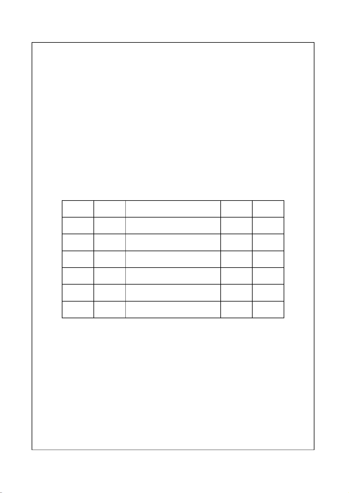
SETTING CLAMP GAP
Set the clamp gap to match your
material thickness.
The clamp gap must be minimum
1.5 x Material Thickness
Example: If 4mm is to be bent, then
the clamp “GAP” must be set to
minimum of 6mm
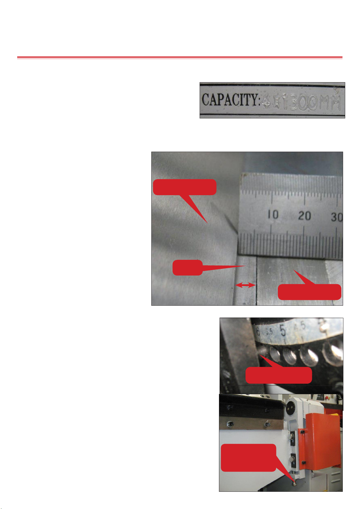
Each panbrake may have a different
mechanism for adjusting the clamp
gap but you must maintain the 1.5
x Material Thickness to prevent
overload and possible damage.
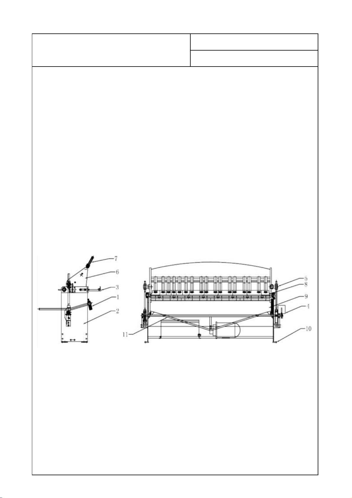
GAP
CLAMP FINGER
FOLDING ARM
BED
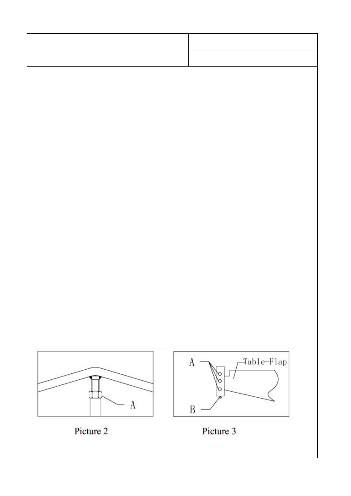
6mm POSITION
You may have to use a combination of top clamp adjustment
and apron adjustment when doing thicker material like 6mm
aluminium.
(1.5 x 6mm = 9mm, so you need a total gap of 9mm)
Example: If the top clamp gap is 6mm the apron must be
dropped down 3mm to keep a 9mm total gap.
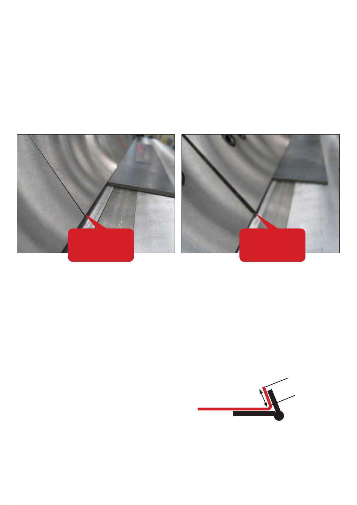
NOTE: Must release locking bolts before adjusting apron
up / down. Tighten when at correct height.
APRON
HEIGHT
ADJUSTMENT