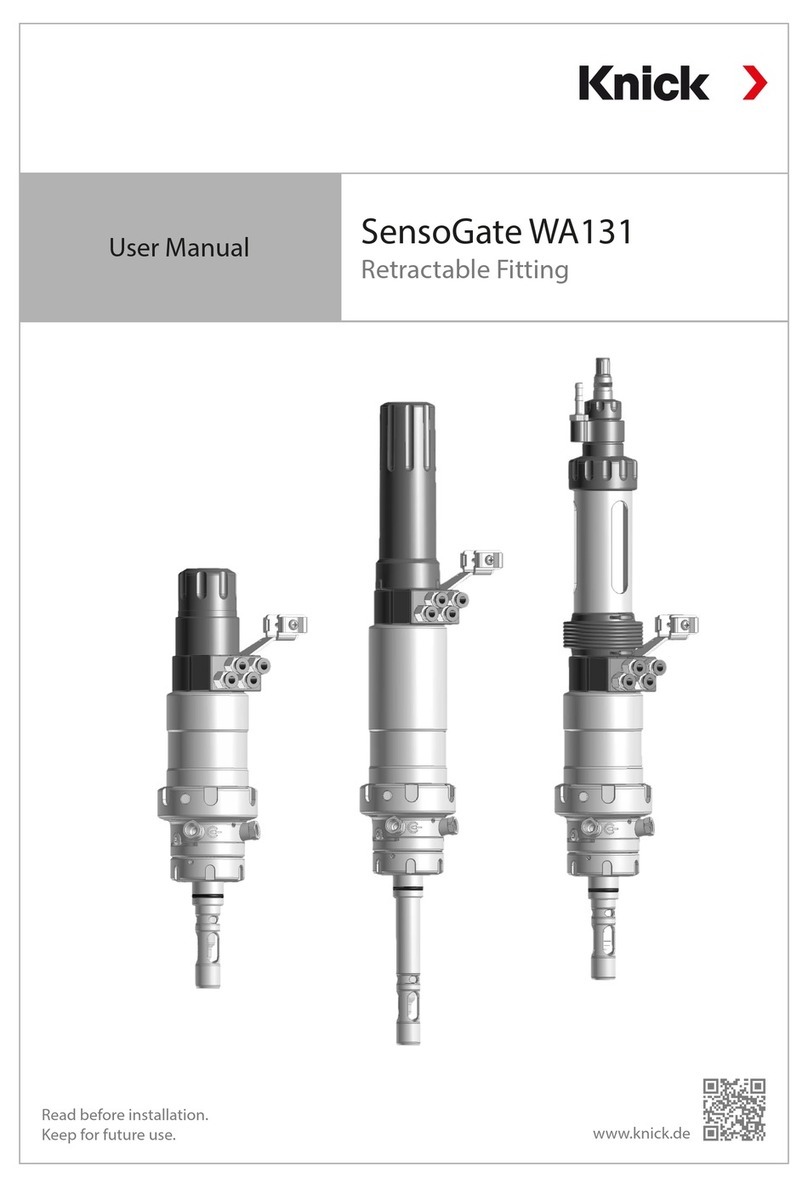
ProLine P16800
3
Table of Contents
1 Safety............................................................................................................................................. 5
1.1 Intended Use.......................................................................................................................................................... 5
1.2 Personnel Requirements.................................................................................................................................... 5
1.3 Residual Risks......................................................................................................................................................... 5
1.4 Functional Safety (Optional)............................................................................................................................. 6
1.5 Installation and Operation ................................................................................................................................ 6
1.6 Disposal.................................................................................................................................................................... 6
2 Product.......................................................................................................................................... 7
2.1 Package Contents................................................................................................................................................. 7
2.2 Product Identification......................................................................................................................................... 7
2.2.1 Product Code............................................................................................................................................ 7
2.2.2 Example of a Version.............................................................................................................................. 7
2.2.3 Nameplate ................................................................................................................................................. 8
2.3 Symbols and Markings ....................................................................................................................................... 10
2.4 Design....................................................................................................................................................................... 11
2.5 Functional Description ....................................................................................................................................... 12
2.6 Input/Output.......................................................................................................................................................... 14
2.7 Voltage Supply ...................................................................................................................................................... 17
2.7.1 Supply of Active Current Output....................................................................................................... 17
2.7.2 Supply of Passive Current Output ..................................................................................................... 18
2.7.3 Auxiliary Power Supply at Voltage Supply Terminal, Output Side ........................................ 19
2.7.4 Auxiliary Power Supply at Voltage Supply Terminal (Output Driver) ................................... 20
2.8 Shielding.................................................................................................................................................................. 21
3 Installation.................................................................................................................................... 22
3.1 Mounting................................................................................................................................................................. 22
3.2 Terminal Assignments ........................................................................................................................................ 23
3.3 Electrical Installation ........................................................................................................................................... 24
4 Configuration................................................................................................................................ 25
4.1 Connections ........................................................................................................................................................... 25
4.1.1 Terminal of the Speed Sensor to the Current Input of the Speed Signal Doubler........... 25
4.1.2 Terminal of the Speed Sensor to the Voltage Input of the Speed Signal Doubler .......... 27
4.2 DIP Switches........................................................................................................................................................... 29
5 Commissioning............................................................................................................................. 31
6 Operation ...................................................................................................................................... 32
6.1 LED Signaling......................................................................................................................................................... 32
7 Maintenance and Repair.............................................................................................................. 33
8 Decommissioning......................................................................................................................... 34
9 Troubleshooting ........................................................................................................................... 35
10 Accessories.................................................................................................................................... 36
