INSTALLATION DATA SHEET
Remove the 3 x M3 screws and the base plate away from the body of the Beacon.
Pierce the cable grommet.
Insert supply/signal cable (maximum 7mm diameter) through the grommet,
pull back slightly (10mm) to allow the grommet to form a weatherproof seal over the cable.
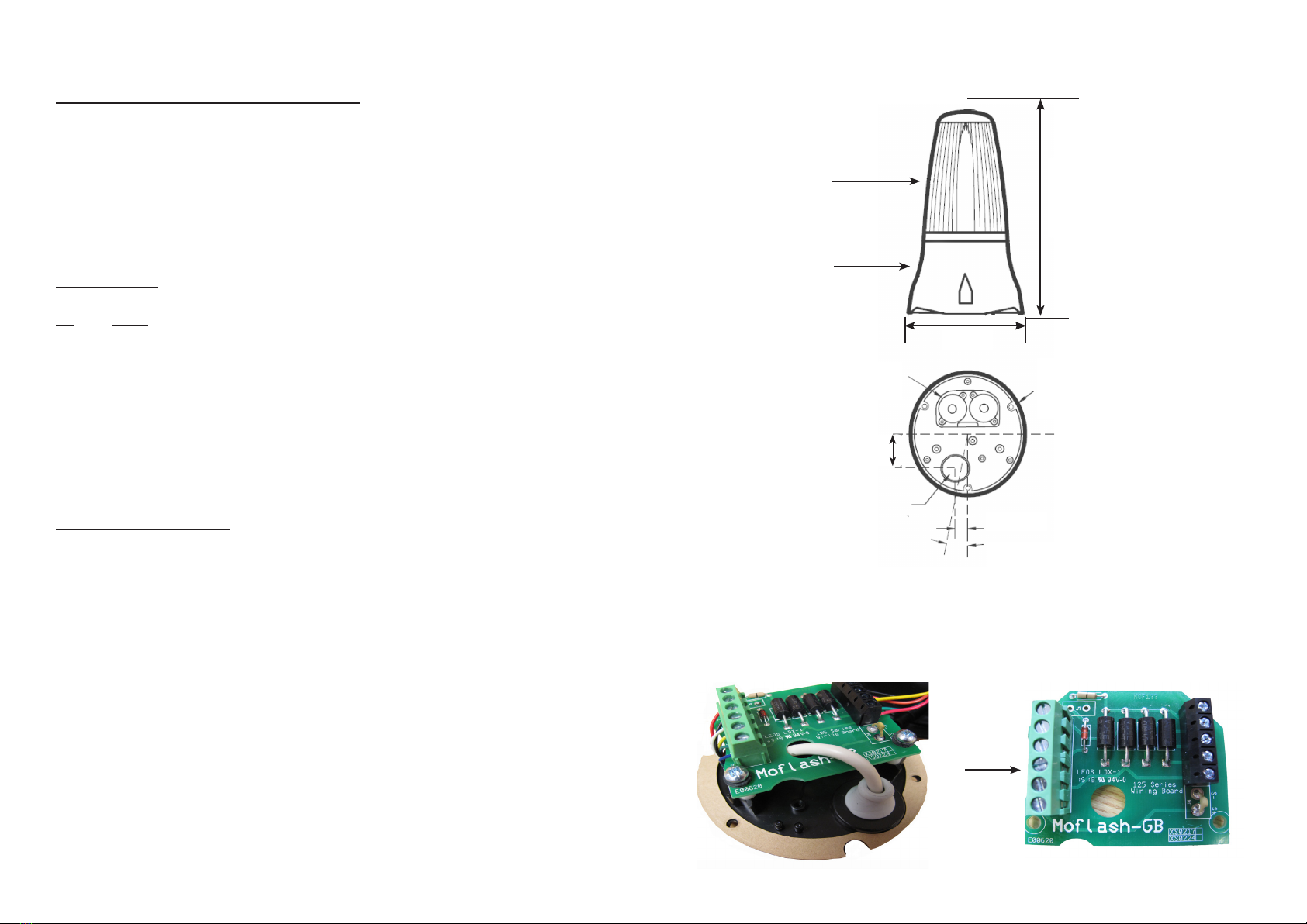
Loop signal/power cable/s through the hole on the PCB as this will act as the strain relief,
See Image 1.
Connect signal/ power cable to the 6 Way Terminal Block. See Below:
Terminal Block
No Mode
1 Power Input +24v DC
2 Return 0v
3 Signal - Sounder +24v (high) 0v (low)
4 Signal - Green LED +24v (high) 0v (low)
5 Signal - Red LED +24v (high) 0v (low)
6 Signal - Amber LED +24v (high) 0v (low)
Replace base plate, ensuring the gasket is in place.
Re-secure the base plate with the 3 x M3 screws.
General Installation Notes
• The DC supply must be fully rectied and smoothed. If the supply is used to power
other equipment, particulary inductive loads, additional suppression will be
required. Typical suppression units would be RS 219-2921 or RS 240-696.
• Installation must be carried out in accordance with latest codes and regulations, by a
qualied electrician.
• Ensure power source is disconnected prior to installation or maintenance to avoid
electric shock.
• Do not handle internal electronic components whilst wiring up.
• Environmental exposure conditions during installation should be dry. Moist or wet
conditions should be avoided.
• The lens material of the beacon is VO rated Polycarbonate UV stable plastic. Do not
clean with petroleum based cleaners.
• The Beacon is weatherproof to IP65, but only when mounted with the lens uppermost
i.e. above the black base.
• Use 3 in total, 4mm diameter xings (not supplied) to secure Beacon to its mounting.
• Avoid mounting the Beacon where it will be subject to excessive vibration.
Terminal Block
(No 1 to 6)
Lens
Black Base
SIDE VIEW
OF BEACON
EXTERNAL
UNDERSIDE
VIEW OF BASE
INTERNAL
VIEW OF BASE
3 Holes x 4.5 DIA
on 88 pcd for
mounting
Piezo
Buzzers
11oSide knockout position
4 x 6.5 mm wide
11 mm
Lead exit
position -
5mm max
cable size
27.6
ø98mm
162mm
Image 1


