manuals.online logo
Brands
  1. Home
  2. •
  3. Brands
  4. •
  5. MOFLASH SIGNALLING
  6. •
  7. Lighting Equipment
  8. •
  9. MOFLASH SIGNALLING X198-02WH-02-05 Manual

MOFLASH SIGNALLING X198-02WH-02-05 Manual

TECHNICAL DATA SHEET
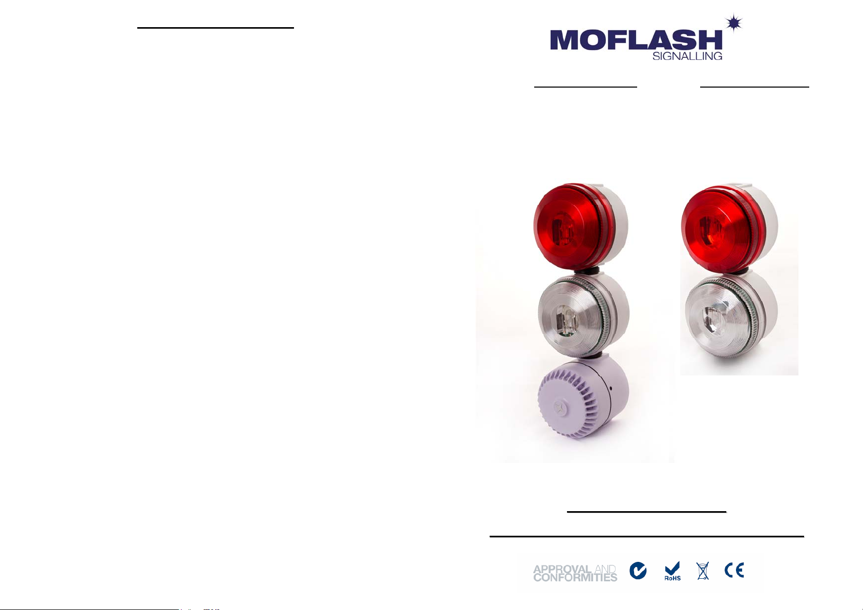
Two Xenon type warning beacons with a Red & Clear lens, connected as one enclosure with
an optional alarm sounder. Designed to meet and exceed the Swedish Fire Alarm regulations,
where an extra bright two colour visual warning signal is required, with low current
consumption. The beacons emit their light through 180 degrees and are suitable for wall
mounting. The units are available with either white or red back boxes and are offered with
two power ratings, 2.5 Watts & 5 Watts.
Code No: Voltage: Light Source: Current: Effective Cd: Comment:
+/-15% (clearlens)
X198-02WH-02-05 24v Dc Xenon 2.5W 180mA 165 White back box
No sounder fitted
X198-02WS-02-05 24v Dc Xenon 2.5W 197mA 165 White back box
With sounder fitted
X198-02RD-02-05 24v Dc Xenon 2.5W 180mA 165 Red back box
No sounder fitted
X198-02RS-02-05 24v Dc Xenon 2.5W 197mA 165 Red back box
With sounder fitted
X199-02WH-02-05 24v Dc Xenon 5W 280mA 185 White back box
No sounder fitted
X199-02WS-02-05 24v Dc Xenon 5W 297mA 185 White back box
With sounder fitted
X199-02RD-02-05 24v Dc Xenon 5W 280mA 185 Red back box
No sounder fitted
X199-02RS-02-05 24v Dc Xenon 5W 297mA 185 Red back box
With sounder fitted
Key Features include:
The unit incorporates a 6 way connection/control solution with a blocking diode
array.
Terminals accept 2.5mm cable incorporating rising clamp protectors.
Operating Voltage: 20 - 27.5v Dc
Weatherproof: IP65
Material: VO Rated ABS back boxes & UV Stable Polycarbonate lenses
Operating Temp: -25°c to +55°c
20mm Cable entry via Red beacon (top or rear entry) to access 6-way barrier strip
connection.
Audible signal is tone selectable (32 tones) with a maximum output of 107dB at 1
meter, with volume control reduction of 10dB.
Moflash part code S00419
Website: www.moflash.co.uk Email: [email protected]
INSTALLATION & TECHNICAL INFORMATION
PLEASE READ PRIOR TO INSTALLATION
S
SW
WE
ED
DI
IS
SH
H
F
FI
IR
RE
E
A
AL
LA
AR
RM
M
V
VI
IS
SU
UA
AL
L
A
AN
ND
D
A
AU
UD
DI
IB
BL
LE
E
S
SI
IG
GN
NA
AL
LL
LI
IN
NG
G
D
DE
EV
VI
IC
CE
ES
S
INSTALLATION DATA SHEET
A 6-way barrier strip is located in the Red lens beacon to allow for connection & control of
the units. Carefully pull the Red lens from the back box, taking care not to pull or strain the
connection leads between the beacons.
Remove either the top or rear M20 conduit knockout to allow for incoming cabling access.
Fit a suitable entry gland (not supplied).
Remove the appropriate fixing hole knockouts in the back box and using the sealing gasket
provided fit onto the required surface using 4mm fasteners (not supplied) The Red beacon
must be mounted above the Clear beacon.
Connect supply wires as shown in the following diagram to suit 2 or 4 wire installations.
Connection Diagram
Ensure 'O' ring is located correctly on base. Snap lens over back box spigot, ensuring lens
screws align with holes in back box, secure lens with No.2 self tapping screws - supplied.
General
BEWARE: Installation must be carried out, in accordance with latest codes and
regulations, by a qualified electrician.
BEWARE: Ensure power source is disconnected prior to installation or maintenance to
avoid electric shock
BEWARE: Do not handle internal electronic components whilst wiring up
BEWARE: Environmental exposure conditions during installation should be dry not moist
or wet conditions
The lens material of the beacon is VO rated Polycarbonate UV stable plastic. Do not
clean with petroleum based cleaners.
Avoid mounting the beacon where it will be subject to excessive vibration.
Black
Brown
Red
Orange
Yellow
Green
+
-
+
-
+
-1
2
+
-
+
-
+
-
1
2
3
4
RED/CLEAR & SOUNDER
MONITOR
1
+
-
2
-
+
FOR 2 WIRE. WIRE LINK ALL + INPUTS,
AND USE ANY - INPUT
Link wire - not supplied
Link wires - not supplied
BUS
RED/CLEAR & SOUNDER
ALL INPUTS BLOCKED
CLEAR (SILENT)
1
+
-
+
2
+
-
-
3
-
+
-
4
-
+
+
+
-
+
-
+
-
Black
Brown
Red
Orange
Yellow
Green
+
-
+
-
+
-
RED
CLEAR
SOUND
4 WIRE
BUS
Mount in this alignment, using fixings in Red Lens Back Box only.
Ø104 73 Ø104 73
308
212
VISUAL AND AUDIBLE
SIGNALLING DEVICE VISUAL SIGNALLING
DEVICE
212
Ø93 93
INTERNAL VIEW
OF RED LENS
BACK BOX
M20
Ø4.5
45°
90° 60
50 60
50

This manual suits for next models

7

Other MOFLASH SIGNALLING Lighting Equipment manuals

MOFLASH SIGNALLING LEDA125-01 Series Manual

MOFLASH SIGNALLING

MOFLASH SIGNALLING LEDA125-01 Series Manual

MOFLASH SIGNALLING RA201-20 Manual

MOFLASH SIGNALLING

MOFLASH SIGNALLING RA201-20 Manual

MOFLASH SIGNALLING X201 Series User manual

MOFLASH SIGNALLING

MOFLASH SIGNALLING X201 Series User manual

MOFLASH SIGNALLING X195 Series Quick start guide

MOFLASH SIGNALLING

MOFLASH SIGNALLING X195 Series Quick start guide

Popular Lighting Equipment manuals by other brands

Life 39.9PF13120N quick start guide

Life

Life 39.9PF13120N quick start guide

Image Engineering CAL1 user manual

Image Engineering

Image Engineering CAL1 user manual

Elation CUEPIX PANEL user manual

Elation

Elation CUEPIX PANEL user manual

Miboxer FUT045A manual

Miboxer

Miboxer FUT045A manual

PXF Lighting Presto LED 1145 DI installation manual

PXF Lighting

PXF Lighting Presto LED 1145 DI installation manual

Cooper safety Ceag 28011 Mounting and operating instructions

Cooper safety

Cooper safety Ceag 28011 Mounting and operating instructions

Lumascape Balitza Mini installation instructions

Lumascape

Lumascape Balitza Mini installation instructions

Armacost Lighting RibbonFlex Home 421501 quick start guide

Armacost Lighting

Armacost Lighting RibbonFlex Home 421501 quick start guide

LumenRadio CRMX Luna user manual

LumenRadio

LumenRadio CRMX Luna user manual

Command Light Knight Series user guide

Command Light

Command Light Knight Series user guide

LED World FA60M50-5M-24V-RGBCCT Important instructions

LED World

LED World FA60M50-5M-24V-RGBCCT Important instructions

Genaray BLT-60 user manual

Genaray

Genaray BLT-60 user manual

Verilux HPLD instructions

Verilux

Verilux HPLD instructions

Binding Union LGE118K Series Technical manual

Binding Union

Binding Union LGE118K Series Technical manual

Velleman HQ POWER VDL6PDB user manual

Velleman

Velleman HQ POWER VDL6PDB user manual

QTX Light QTFX-F1 user manual

QTX Light

QTX Light QTFX-F1 user manual

involight MH5R Beam user manual

involight

involight MH5R Beam user manual

Good Earth Lighting G9712L-T5-WHESI quick start guide

Good Earth Lighting

Good Earth Lighting G9712L-T5-WHESI quick start guide

manuals.online logo
manuals.online logoBrands
  • About & Mission
  • Contact us
  • Privacy Policy
  • Terms and Conditions

Copyright 2025 Manuals.Online. All Rights Reserved.