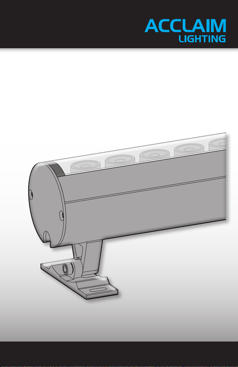
Acclaim Lighting Aqua Graze User manual

User guide
www.acclaimlighting.com Aqua Graze


1
www.acclaimlighting.com
CONTENTS
INTRODUCTION ......................................................2
Welcome 2
Safety, maintenance and cleaning 2
INSTALLATION.........................................................3
Aqua Graze mounting and adjusting 3
Aqua Driver mounting 4
Control input connections 4
Creating a wireless DMX input 5
Converting a 0-10V input 5
Output connections 6
Port connection cables 6
Fixture support with Aqua Driver 150 7
Fixture support with Aqua Driver 400 8
Connector pin outs 9
Fixture drive current selection 9
Port grouping 10
DMX channel layouts 11
Power input 13
Aqua Driver mode control 14
FURTHER INFORMATION ......................................17
Aqua Graze and Driver specifications 17
Dimensions 18
Aqua Graze 18
Aqua Driver 150 19
Aqua Driver 400 20
Limited product warranty 21

2www.acclaimlighting.com
SAFETY
•Ensure that the power input is supplied from a correctly fused, earthed and
environmentally protected location.
•While Aqua Graze fixtures are rated to IP68* for submersible operation, the Aqua Driver
units have IP20 ratings, for dry location installations only.
MAINTENANCE
CAUTION: Always isolate mains power before starting maintenance operations.
•Ensure that all mounting (and device) screws/bolts are fully tight and free of corrosion.
•Ensure there is no deformation to the housing, lenses or fixing points.
•Check that all power supply cables are free from physical damage or material fatigue.
•Use only genuine spare parts supplied by Acclaim Lighting.
CLEANING
•Use a moist, lint-free cloth when cleaning each fixture.
•Never use alcohol or solvents.
SAFETY, MAINTENANCE AND CLEANING
INTRODUCTION
WELCOME
Welcome to the Aqua Graze and Aqua Driver from Acclaim Lighting. This range of high
output, submersible LED flood fixtures offer IP68 submersible properties thanks to their
anodized oxidation aluminum housings and fully sealed joints.
There are two sizes of fixture:
•Aqua Graze 1’ with 12 LED emitters
•Aqua Graze 4’ with 48 LED emitters
With a comprehensive choice of emitter types:
•2700K, 3000K, 3500K or 4000K white
•RGBW (W=4000K)
•RGBA
And an appropriate range of lens options:
•10Ox 10O
•25Ox 25O
•40Ox 40O
•60Ox 60O
•10Ox 60O
•30Ox 60O
The accompanying Aqua Driver controllers (Aqua Driver 150 to control up to four fixtures;
Aqua Driver 400 to control up to eight fixtures) operate from mains inputs ranging from 100
to 277VAC, 50/60Hz (autosensing) and provide constant current PWM drive to the output
ports. The Aqua Driver units can either operate independently to provide static dimming or
multiple chases, or can accept a DMX input for inclusion into an external control system.
The Aqua Driver units are housed within black power-coated steel enclosures with IP20
ratings for dry indoor locations. The driver units are designed to be wall mounted.

3
www.acclaimlighting.com
INSTALLATION
AQUA GRAZE MOUNTING AND ADJUSTING
When installing Aqua Graze fixtures, ensure that the surface is level and that nothing is
protruding to damage the mounting brackets. Suitable mounting surfaces include steel,
aluminum, concrete or wood structures.
Each mount bracket has two slots measuring
0.39” x 0.18” (10 x 4.5mm) and the base has a
thickness of 1/8” (3mm). Select bolts or screws
(not supplied) that fit the mount bracket base(s)
correctly and are particularly suited to the
mounting surface.
The Aqua Graze can be tilted roughly 53Oin
each direction from vertical. Use a 1/8” (3mm)
Allen wrench to loosen the tilt bolts on the
mounting brackets at each end of the fixture.
If a mount bracket needs to be moved along the length of the fixture, you will need to
temporarily remove the mount bracket base in order to gain access to the slide screw.
TO ADJUST THE MOUNT BRACKET
1 Use a 1/8” (3mm) Allen wrench to loosen the
tilt bolt until the mount bracket base can be
removed from the pillar:
2 Use a 1/16” (1.5mm) Allen wrench to loosen the slide screw and move the pillar to the
required position.
3 Re-tighten the slide screw.
4 Refit the base onto the pillar and tighten the tilt bolt.
53O
53O
Slide screw 1/16”/ 1.5mm
Allen wrench required
Tilt bolt 1/8”/ 3mm
Allen wrench required
Mount
bracket
base
Mount
bracket
pillar

4www.acclaimlighting.com
AQUA DRIVER MOUNTING
Both Aqua Driver models can be wall mounted either vertically or horizontally as required.
Two slotted holes (Ø 0.23” x 0.47” / Ø 6 x 12mm) are available on each side for mounting
purposes - see “Dimensions”on pages 19 and 20.
CONTROL INPUT CONNECTIONS
Both Aqua Driver models can either operate in
a standalone manner or be controlled by DMX.
Three-pin terminal block IN and OUT ports
are located on the front panel. In addition, the
Aqua Driver 150 also provides 3-pin XLR IN
and OUT sockets. See below for useful DMX
tips. Connect your DMX cables to the terminal
blocks as shown here:
TIPS FOR ACHIEVING SUCCESSFUL DMX CONTROL
•Do not exceed a total cable length of 3,900 ft (1200m) without buffering.
•Do not exceed a total of 32 devices/fixtures on a single line without buffering.
•Use only connection cables with a characteristic impedance of 120Ω, preferably where
the DMX + and DMX – data lines are twisted around each other and the ground link exists
as a coaxial screen surrounding the inner cores, such as Belden® 9842 or equivalent.
•Connect a 120Ω terminating resistor between the DMX + and DMX – output connections
of the final fixture.
•Do not introduce a passive Y-split into the control cabling. If it is necessary to split the
control link in order feed fixtures located in different directions, use a powered DMX
splitter/buffer.
•Ensure that the DMX + and DMX – connections do not become crossed at any point.
Insert the terminal block into the DMX socket
and ensure that it fully clicks into place. Repeat
for the DMX OUT if the control signal needs to
be fed to another device.
Aqua Driver
150 models
only

5
www.acclaimlighting.com
CREATING A WIRELESS DMX INPUT
The optional Acclaim Lighting Aria units allow you create a wireless DMX link up to 2600
feet (792m) line of sight, between your control output and the Aqua Driver. Setup and
configuration is straightforward:
1 Connect the DMX output of one Aria unit to the DMX input (using either the terminal
block or the XLR connector) of the Aqua Driver.
2 Connect your DMX control source to the DMX input of the other Aria unit (when a valid
signal is sensed, the Aria unit will automatically configure itself as a transmitter).
3 Ensure both Aria units are using the same radio channel.
The DMX signal presented at the transmitter will be replicated at the receiver and be fed to
the Aqua Driver. See the Aria Wireless DMX guide for more details.
CONVERTING A 0-10V INPUT
The optional Acclaim Lighting UDM (Universal Dimming Module) unit allows you to
collectively control a group of Aqua Graze fixtures using a 0-10V analog input. Setup and
configuration is straightforward:
1 Connect the DMX output of the UDM unit to the DMX input (using either the terminal
block or the XLR connector) of the Aqua Driver.
2 Connect your 0-10V control source to the appropriate input of the UDM unit.
3 Configure the UDM to perform the conversion. Note: The UDM also has a mains power
supply pass through to which the Aqua Driver can be connected; thus, only one mains input is
required to supply the two devices.
The 0-10V signal presented at the UDM will be converted into a single DMX channel and
fed to the Aqua Driver; the Aqua Driver will need to be placed into 1 Group mode. The single
channel input best suits Aqua Graze White emitters. See the UDM guide for more details.
Power connections
not shown
Power connections not shown
Aqua Driver

6www.acclaimlighting.com
OUTPUT CONNECTIONS
The Aqua Drivers have multiple constant current output ports,
each of which uses an 8-pin terminal block. Each output port
provides multiple channels, the addressing of which are
decided by the front panel switch settings (see
“Aqua Driver mode control” on page 14).
PORT CONNECTION CABLES
Each Aqua Graze fixture is supplied with a 100’(30m) cable terminated in an 8-pin terminal
connector. In situations where this supplied cable is shortened and then wired into a
separate supply cable, ensure the conductors of the supply cable are of sufficient size and
that the total cable length (including that which remains of the Aqua Graze cable) is not
exceeded:
Conductor size Maximum length (including Aqua Graze cable)
•18 AWG (0.823mm2) Up to 100’(30m)
•14 AWG (2.081mm2) Up to 125’(38m)
•12 AWG (3.309mm2) Up to 150’(45m)
4’1’
700mA350mA
IMPORTANT: 1’ xtures require a dierent drive
current setting to the longer 4’xtures - it is vitally
important to select the correct setting to avoid
damage to the xtures. The drive current setting
aects all outputs equally, so it is not possible to mix
the two sizes on the same driver unit. See “Fixture drive
current selection” on page 9.

7
www.acclaimlighting.com
AQUA GRAZE 4’ FIXTURES
A maximum of two Aqua Graze 4’ fixtures can be used on a single Aqua Driver 150. Any of
the port grouping options (1 Group, 2 Group or 4 Group - see page 10) are appropriate for
these fixtures.
FIXTURE SUPPORT WITH AQUA DRIVER 150
AQUA GRAZE 1’ FIXTURES
Up to four Aqua Graze 1’ fixtures can be used on a single Aqua Driver 150. Any of the port
grouping options (1 Group, 2 Group or 4 Group - see page 10) are appropriate for these
fixtures.
21
ON
1’ xtures require a 350mA drive current
On the 2-way switch block, ensure both switches are in
the OFF position. Both of the adjacent indicators will be
OFF during operation.
1’
1’1’1’
21
ON
4’ xtures require a 700mA drive current
On the 2-way switch block, ensure both switches are in
the ON position. Both of the adjacent indicators will be
ON during operation.
4’ 4’

8www.acclaimlighting.com
AQUA GRAZE 4’ FIXTURES
A maximum of four Aqua Graze 4’ fixtures can be used on a single Aqua Driver 400. Any
of the port grouping options (1 Group, 2 Group, 4 Group or 8 Group - see page 10) are
appropriate for these fixtures.
FIXTURE SUPPORT WITH AQUA DRIVER 400
AQUA GRAZE 1’ FIXTURES
Up to eight Aqua Graze 1’ fixtures can be used on a single Aqua Driver 400. Any of the port
grouping options (1 Group, 2 Group, 4 Group or 8 Group - see page 10) are appropriate for
these fixtures.
21
ON
1’ xtures require a 350mA drive current
On the 2-way switch block, ensure both switches are in
the OFF position. Both of the adjacent indicators will be
OFF during operation.
21
ON
4’ xtures require a 700mA drive current
On the 2-way switch block, ensure both switches are in
the ON position. Both of the adjacent indicators will be
ON during operation.

9
www.acclaimlighting.com
CONNECTOR PIN OUTS
AQUA GRAZE RGBW/A
These connections are used for RGBW/A versions of the EO, SO and HO Aqua Graze fixtures:
AQUA GRAZE WHITE
These connections are used for White versions of the EO, SO and HO Aqua Graze fixtures:
+
R–
G–
B–
W–
Black
Red
Green
Yellow
White
1
2
3
4
5
6
7
8
+
Circuit 1–
Circuit 2–
Circuit 3–
Circuit 4–
Black
Red
Green
Yellow
White
1
2
3
4
5
6
7
8
FIXTURE DRIVE CURRENT SELECTION
Aqua Graze 1’fixtures require a different drive current setting to the larger
4’ fixtures - it is vitally important to select the correct setting to avoid
damage to the xtures. The drive current setting affects all outputs equally,
so it is not possible to mix the 1’and 4’ fixture lengths on the same driver.
Note: Changes to the drive current must be made while the Aqua Driver unit is
powered down.
1’ FIXTURES (350mA)
On the 2-way switch block, ensure both switches
are in the OFF position. Both of the adjacent
indicators will be OFF during operation.
4’ FIXTURES (700mA)
On the 2-way switch block, ensure both switches
are in the ON position. Both of the adjacent
indicators will be ON during operation.
21
ON
21
ON

10 www.acclaimlighting.com
PORT GROUPING
AQUA DRIVER 150
The four output ports can either be used individually under separate control or grouped
in either pairs, or grouped all as one control block. The grouping status is determined by
switches 1 and 2 of the 6-way switch block (see page 14).
4 Group
All four ports
are controlled
individually:
2 Group
Ports 1 and 2 are controlled together
as one group. Ports 3 and 4 are
controlled as a separate group:
1 Group
All four ports
are controlled
collectively:
DMX channels
required
White: 4 channels
RGBW/A: 16 channels
DMX channels
required
White: 2 channels
RGBW/A: 8 channels
DMX channels
required
White: 1 channel
RGBW/A: 4 channels
8 Group
All eight ports
are controlled
individually:
4 Group
The eight ports are paired and jointly
controlled as follows: Ports 1 and 2, ports
3 and 4, ports 5 and 6, ports 7 and 8:
DMX channels
required
White: 8 channels
RGBW/A: 32 channels
DMX channels
required
White: 4 channels
RGBW/A: 16 channels
1 Group
All eight ports
are controlled
collectively:
DMX channels
required
White: 1 channel
RGBW/A: 4 channels
2 Group
Ports 1, 2, 3 and 4 are controlled
together as one group. Ports 5, 6, 7 and
8 are controlled as a separate group:
DMX channels
required
White: 2 channels
RGBW/A: 8 channels
AQUA DRIVER 400
The eight output ports can either be used individually under separate control or grouped in
either pairs, fours or grouped all as one control block. The grouping status is determined by
switches 1 and 2 of the 6-way switch block (see page 14).

11
www.acclaimlighting.com
DMX CHANNEL LAYOUTS
The number of DMX channels required to control the connected fixtures depends upon the
following settings, which are configured using the 6-way switch block:
•Port grouping, and
•Fixture type
AQUA DRIVER 150
The various DMX channel requirements for the various port grouping and fixture type
combinations on the Aqua Driver 150 are listed here:
DMX RGBW/A RGBW/A RGBW/A
address 4 Group 2 Group 1 Group
1 Port 1: Red Ports 1 & 2: Red All: Red
2 Port 1: Green Ports 1 & 2: Green All: Green
3 Port 1: Blue Ports 1 & 2: Blue All: Blue
4 Port 1: White Ports 1 & 2: White All: White
5 Port 2: Red Ports 3 & 4: Red
6 Port 2: Green Ports 3 & 4: Green
7 Port 2: Blue Ports 3 & 4: Blue
8 Port 2: White Ports 3 & 4: White
9 Port 3: Red
10 Port 3: Green
11 Port 3: Blue
12 Port 3: White
13 Port 4: Red
14 Port 4: Green
15 Port 4: Blue
16 Port 4: White
DMX White White White
address 4 Group 2 Group 1 Group
1 Port 1: White Ports 1 & 2: White All: White
2 Port 2: White Ports 3 & 4: White
3 Port 3: White
4 Port 4: White
See “Port grouping”on page 10 and “External DMX control mode” on page 14 for DMX
address configuration details.
4’1’
700mA
350mA
IMPORTANT: 1’ xtures require a dierent drive
current setting to the longer 4’xtures - it is vitally
important to select the correct setting to avoid
damage to the xtures. The drive current setting
aects all outputs equally, so it is not possible to mix
the two sizes on the same driver unit. See “Fixture drive
current selection” on page 9.

12 www.acclaimlighting.com
DMX RGBW/A RGBW/A RGBW/A RGBW/A
address 8 Group 4 Group 2 Group 1 Group
1 Port 1: Red Ports 1 & 2: Red Ports 1 to 4: Red All: Red
2 Port 1: Green Ports 1 & 2: Green Ports 1 to 4: Green All: Green
3 Port 1: Blue Ports 1 & 2: Blue Ports 1 to 4: Blue All: Blue
4 Port 1: White Ports 1 & 2: White Ports 1 to 4: White All: White
5 Port 2: Red Ports 3 & 4: Red Ports 5 to 8: Red
6 Port 2: Green Ports 3 & 4: Green Ports 5 to 8: Green
7 Port 2: Blue Ports 3 & 4: Blue Ports 5 to 8: Blue
8 Port 2: White Ports 3 & 4: White Ports 5 to 8: White
9 Port 3: Red Ports 5 & 6: Red
10 Port 3: Green Ports 5 & 6: Green
11 Port 3: Blue Ports 5 & 6: Blue
12 Port 3: White Ports 5 & 6: White
13 Port 4: Red Ports 7 & 8: Red
14 Port 4: Green Ports 7 & 8: Green
15 Port 4: Blue Ports 7 & 8: Blue
16 Port 4: White Ports 7 & 8: White
17 Port 5: Red
18 Port 5: Green
19 Port 5: Blue
20 Port 5: White
21 Port 6: Red
22 Port 6: Green
23 Port 6: Blue
24 Port 6: White
25 Port 7: Red
26 Port 7: Green
27 Port 7: Blue
28 Port 7: White
29 Port 8: Red
30 Port 8: Green
31 Port 8: Blue
32 Port 8: White
AQUA DRIVER 400
The various DMX channel requirements for the various port grouping and fixture type
combinations on the Aqua Driver 400 are listed here:
See “Port grouping”on page 10 and
“External DMX control mode”on page 14
for DMX address configuration details.
DMX White White White White
address 8 Group 4 Group 2 Group 1 Group
1 Port 1: White Ports 1 & 2: White Ports 1 to 4: White All: White
2 Port 2: White Ports 3 & 4: White Ports 5 to 8: White
3 Port 3: White Ports 5 & 6: White
4 Port 4: White Ports 7 & 8: White
5 Port 5: White
6 Port 6: White
7 Port 7: White
8 Port 8: White

13
www.acclaimlighting.com
POWER INPUT
The fixed power cord is supplied as standard with US color coding and bare tails. For
international installations, wire according to local codes.
Power cord colors
The red front panel indicator will illuminate when power is applied. The other two indicators
located just below the power indicator are not used.
IN-RUSH CURRENT
The Aqua Drivers use switched mode power supplies which exhibit a trait known as
‘in-rush current’ when they are first powered on. This is caused by the various capacitive
components initially topping themselves up with power. The in-rush current period lasts
only milliseconds, however, if you are using multiple units on a single supply, ensure that the
breakers used are rated to support inrush currents without tripping during startup.
The Aqua Driver power requirements are as
follows:
•Voltage: 100-277VAC 50/60Hz

14 www.acclaimlighting.com
96385
21
0741
256128643216
DMX mode: ON
8
DMX address
421
ON
AQUA DRIVER MODE CONTROL
The manner in which the Aqua Driver output ports are grouped and operate is determined
by the settings of the three switch blocks located on the front panel. There are three main
ways to use the Aqua Driver:
•External DMX control mode
•Standalone mode using internal chase programs
•Standalone mode using adjustable static dimming
EXTERNAL DMX CONTROL MODE
To allow DMX control you need to:
1 Set switch 10 of the
10-way switch block
ON to choose DMX
mode.
2 Select the required
DMX base address
using switches 1 to 9
of the 10-way switch
block. Each of the nine switches is ‘weighted’ with a value as shown here. Numerous apps
are available to assist you with configuring the correct switch combinations for a given
DMX address. Note: The total number of DMX channels required for control will depend upon
the chosen port grouping and fixture types (see “DMX channel layouts” on page 11).
Fixture type
635241
ON
Port grouping
635241
ON
3 Use switches 1 and 2 of the 6-way switch block to
choose the required grouping of channel outputs as
required by the Aqua Grazes being connected and
their required functions.
1 2 Port grouping
Driver 150 Driver 400
OFF OFF 1 group 1 group
ON OFF 2 group 2 group
OFF ON 4 group 4 group
ON ON 4 group 8 group
See “Port grouping”on page 10 for more details.
4 Use switches 4 and 5 of the 6-way switch block to
set the type of Aqua Graze fixtures being used:
4 5 Fixture type
ON OFF White
ON ON RGBW/A
Note: The chosen fixture type (RGBW/A or White) is
applied globally to all ports. However, the electrical
characteristics of the ports do not change (only their
logical addressing configuration), so it is possible to
mix white fixtures into an RGBW set up. As such, the
various white emitters of the fixture would respond
individually to the separate RGBW channel addresses.
Note: Ensure the correct fixture
current is selected - see page 9.

15
www.acclaimlighting.com
Standalone mode: OFF
968107
ON
STANDALONE MODE USING INTERNAL CHASE PROGRAMS
In standalone mode, all four ports are treated as one group. Note: all switch settings can be
changed when the driver is off or on. To configure the Aqua Driver for standalone chase mode
you need to:
1 On the 10-way switch block, set switch 10 OFF to
choose standalone mode.
Fade time
3241
Program
968107
ON
Speed
63574
2 Use switches 1 to 3 of the 10-way switch block to
choose the required fade time between chase steps.
If all three switches are OFF, the chase states will snap
between each other. All three switches ON will produce
the smoothest fade (Note: switch 3 is weighted as the
most significant bit).
3 Use switches 4 to 6 of the 10-way switch block to
choose the required speed of chase. If all three switches
are OFF, the chase will run at its fastest speed, with 0.1
seconds between steps.
4 5 6 Speed
OFF OFF OFF 0.1 seconds
ON OFF OFF 0.2 seconds
OFF ON OFF 0.5 seconds
ON ON OFF 1 second
OFF OFF ON 5 seconds
ON OFF ON 10 seconds
OFF ON ON 20 seconds
ON ON ON 30 seconds
4 Use switches 7 to 9 of the 10-way switch block to
choose the required program. If all three switches
are ON, an Auto mode will cycle between all of
the available programs.

16 www.acclaimlighting.com
Standalone mode: OFF
968107
ON
STANDALONE MODE USING ADJUSTABLE STATIC DIMMING
In standalone mode, all four ports are treated as one group. Note: all switch settings can
be changed when the driver is off or on. To configure the Aqua Driver for standalone static
dimming you need to:
1 On the 10-way switch block, set switch 10 OFF to
choose standalone mode.
2 On the 6-way switch block, set switch 6 ON to
choose manual dimming mode.
Manual dimming mode: ON
635241
ON
1 On the 10-way switch block, use
switches 1 to 8 to choose the
dimming level (for all emitters
of every connected Aqua Graze
fixture). When all eight switches
are OFF, the fixtures will be at
0%; conversely, all switches
ON will produce 100% output.
The switches are arranged as a
binary byte, with switch 1 as the
least significant bit and switch 8
as the most significant.
96
38
5
21
0741
MSB••••
Dimming level
••LSB
ON

17
www.acclaimlighting.com
Release 1.1b
FURTHER INFORMATION
AQUA GRAZE AND DRIVER SPECIFICATIONS
AQUA GRAZE FIXTURES
Color models 2700K, 3000K, 3500K and 4000K white
RGBW (W=4000K), RGBA
Beam angle options 10ox 10o, 25ox 25o, 40ox 40o, 60ox 60o, 10ox 60oor 30ox 60o
Illuminance (lm/ft2) Up to 729 (3000K 10ox 60ovariant)
Lumen maintenance (L70) 150,000 hours (25oC)
Control DMX via Aqua Driver 150, 0-10V also possible using UDM
Operating voltage 24VDC constant current
Power consumption 12W (1’ model), 48W (4’ model)
Fixture cabling 98.4’ (30m) cable with 8-pin terminal block termination
Housing Anodized oxidation aluminum body, glass top lens
Mounting 53oswivel mounts included
IP rating IP68, submersible up to 10’(3m)
IK rating IK06, protection against 1 joule impact
Operating temperature -40oF to 122oF (-40oC to 50oC)
Weight 1.5 lbs/0.68kg (1’ model), 6 lbs/2.72kg (4’ model)
AQUA DRIVER 150 AND 400 CONTROLLERS
Control DMX plus internal standalone chases and dimming
Input voltage 100 to 277VAC (50/60Hz) - auto sensing
Output 350 to 700mA constant current
Output ports Aqua Driver 150: 4
Aqua Driver 400: 8
Operating temperature 0oF to 158oF (-20oC to 70oC)
Housing Aluminum
IP rating IP20, indoor dry location
IK rating IK06, protection against 1 joule impact
Certifications

18 www.acclaimlighting.com
DIMENSIONS
AQUA GRAZE
Fixture weights:
1’ models: 1.5 lbs (0.68 kg)
4’ models: 6 lbs (2.72 kg)
1.97" (50mm)
2.95" (75mm)
2.56"
(65mm)
2.13"
(54mm)
0.39 x Ø0.18” (10 x Ø4.5mm)
1' (305mm)
3.07” (78mm)
Ø0.48” (Ø12.3mm)
4' (1220mm)
23.94” (608mm)
Ø0.48” (Ø12.3mm)
This manual suits for next models
1
Table of contents
Other Acclaim Lighting Lighting Equipment manuals

Acclaim Lighting
Acclaim Lighting Flood One EO Series User manual

Acclaim Lighting
Acclaim Lighting ART-4 User manual

Acclaim Lighting
Acclaim Lighting Terra Linear User manual

Acclaim Lighting
Acclaim Lighting Flex One Exterior Series User manual

Acclaim Lighting
Acclaim Lighting AL Dot User manual

Acclaim Lighting
Acclaim Lighting Unity SNS2019 User manual

Acclaim Lighting
Acclaim Lighting AL-BAR-AC-DMX-1200-RGB User manual

Acclaim Lighting
Acclaim Lighting Flex Tube Mini User manual

Acclaim Lighting
Acclaim Lighting Ai Flex Interior User manual

Acclaim Lighting
Acclaim Lighting Flex Tube Pixel User manual