NBCUniversal LIGHTBLADE LB800 User manual

Lightblade LB800
User Guide
Revision 1.0 — January, 2019
Information and specications in this document are subject to
change without notice.
www.cineolighting.com

2
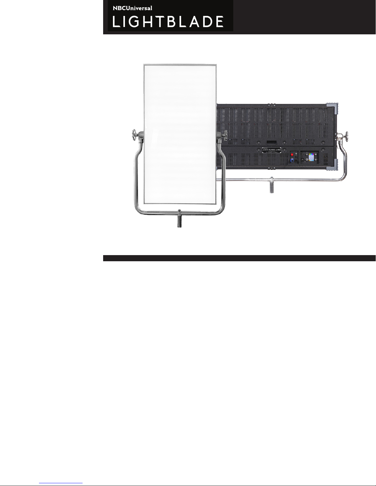
NBCUniversal and Cineo have developed the
next generation of large, soft digital lighting: the
Lightblade LB800. The LB800 delivers up to 50,000
lumens of beautiful, easily controllable, full-gamut
light across a diused 2’x 4’ aperture. With built
in power supply and silent operation, the LB800
delivers 800 watts of power in a package that
weighs 55 lbs and is less than 5.5 inches deep.
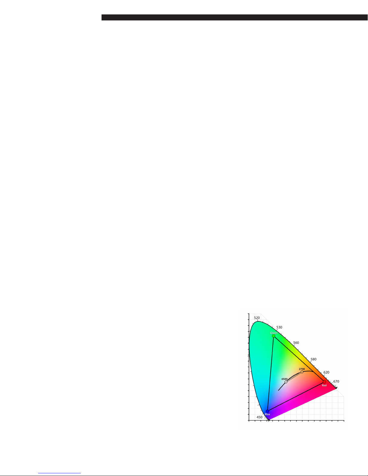
In addition to Cineo’s proprietary phosphor-
converted white light LEDs, the LB800 uses
phosphor-converted saturated color LEDs. The
phosphor-converted LEDs use the exact same dies
as the white LEDs, so all light emitting elements
of the LB800 carry identical thermal stability, and
perform over time with identical dierential aging.
So after years of service, color stability remains
consistent.
The LB800 is the rst of the Lightblade products to
operate on a Linux OS, providing the platform to
support future smart stage innovations. The LB800
incorporates an intuitive control strategy that
allows predictable, repeatable results, either using
the graphic on-board control panel or remotely
with wired DMX/RDM or built-in wireless CRMX
control.
The Lightblade LB800 is built on a multi-zone
architecture, i.e. the xture can be operated as a
single, 2’x 4’ soft source, or it can be operated as
10 individual xtures in a single chassis, capable of
generating dynamic lighting eects.
The unit is remotely controllable using DMX/RDM
and network protocols including sACN and ARTNet
(coming Q2 2019). Remote operations include a
variety of Personalities, including HSIC, RGBC and
BiColor (white-only). DMX resolutions include both
8-bit and 16-bit operation.
The LB800 is passively cooled for completely
silent operation, ruggedly built, water resistant
and includes an integrated power supply for easy
setup.
Welcome to LB800 from NBCUniversal and Cineo
LB800

3
General Notes
1. Please read through this manual carefully before operating the LB800, and keep this manual for future
reference.
2. There are numerous safety instructions and warnings that must be adhered to for your
own safety.
3. The LB800 is not intended for residential use. It is intended for use in a professional studio.
4. The LB800 must be serviced by a qualied technician.
5. The LB800 is rated as IP22 – for damp environments.
6. Lightblade products are not certied for use in hazardous locations.
7. The LB800 has a typical operating temperature of 50°C (122°F).
Fixture Set Up
Read these safety instructions carefully to ensure xture and accessories are used safely.
Ensure the Junior Pin adapter is correctly mounted onto the yoke before rigging.
Always use secondary safety cables of suitable length when hanging LB800 units.
The LB800 weighs 55 lbs. (25 kg) excluding accessories. The combined weight should be considered
when choosing a suitable safety cable.
Safety cables must securely be attached to the yoke on LB800 and be as short as possible to reduce travel
distance if primary hanging accessory fails.
Ensure that the yoke lock is correctly tightened when manipulating LB800 in the required orientation for
safety purposes.
Ensure the LB800 is operated within an ambient temperature range of -20 to +40°C
(-4 to 104°F).

4
System Components, Connections and Controls
All connectors and system controls for the LB800 are located on the back of the unit. In addition to its
full color heads-up display, optically encoded rotary knobs give access to menu selections and local
control inputs. Hard power connections and switches allow for easy set up and strike. The 5 pin DMX
connections, RJ45 Ethernet port, embedded wireless receivers, RDM responders and powered USB ports
support many options for external control.
Power
The LB800 unit is controlled by an internal power supply. 110 – 220VAC is provided to the unit via a
locking PowerCon connector, located on the back control panel.
NOTES:
1. Ensure the power cable is disconnected before servicing.
2. Do not connect to a variable supply, such as a dimmer rack.
3. The power cable should be plugged into the power supply before switching the power ON. The power
supply should be switched OFF before removing the power cable.
4. A self-resetting circuit breaker is located near the power connection, which requires no user
interaction. If the breaker trips, it will reset within one minute of tripping.
Displays Screen
A full-color screen displays the status of each DIM, CCT, SATURATION and HUE control value at all times.
The color ribbons on the top and bottom of the display give a visual reference for both the CCT and the
HUE. DIM value and SATURATION are represented as a percentage. In DMX mode, this display reects the
current DMX channel assignment as well as the current personality and communication bitrate.
Color Space
The Lightblade Edge uses two separate LED engines
to independently generate accurate white light,
variable from 2700K to 6500K, and an extended RGB
gamut for broad saturated color space. The CIE 1931
diagram illustrates the Lightblade Edge color space.

5
Controls
Setup of the LB800 is can be accomplished either using the large knob with the color display, or remotely
using RDM.
Accessing the Setup Menu
The xture can be set up via the control panel as follows:
1. Push and hold the large knob for approximately 3 seconds. The status display will now show the top
level menu options.
2. Turn the large knob until the desired control selection is highlighted: LOCAL, DMX, PRESETS or
SETTINGS.
3. Push the knob again to select menu category. The menu advances to display various options for
the selected function.
Note that in any menu, press and holding the large knob for 3 seconds will return you to this root menu.
LOCAL Mode
When LOCAL mode is selected, all functions of the xture are managed through the 4 rotary encoders;
feedback and functions are shown on the display screen.
Lower left knob (Large) Photo-Accurate Dimming
The dimming curve on the LB800 follows a strategy that provides relative output levels that correspond
to image capture. Both DMX values and local control levels directly correlate to camera stops in a
meaningful way. The result is extremely predictable light levels within the full output range of the xture.
0-100% dimming is controlled by turning the large knob. Pushing the knob cycles the output at these
levels: 20%, 40%, 60%, 80% and 100%.
The following table shows the relationship between LOCAL values as they relate to camera stops:
DMX Value % Output increase Stop Increase
(0-100)
20% 100 0
40% 200 1
60% 400 2
80% 800 3
100% 1600 4

6
Here are examples of how to accurately match camera stops to dimming levels in Local Mode:
Local Dimming: The Rule of 20 (0-100 scale)
Increase output 1 Stop: Add 20 units (fc/lux is doubled)
Decrease output 1 Stop: Subtract 20 units (fc/lux is reduced 50%)
Adjust ½ Stop = 10 Units (0-100)
Adjust ¼ Stop = 5 Units (0-100)
Lower right knob: CCT Adjustment
The color temperature (CCT) of the xture is controlled by turning the lower right knob in a continuously
variable range of 2700K to 6500K. Pushing the lower right knob cycles the CCT of the xture between
popular settings: 2700, 3200, 4300, 5600 and 6500K.
Upper left knob: Color Saturation
The SATURATION of color added to the base white light is controlled by the upper left knob, which has
presets at 0%, 10%, 20%, 50%, 80% and 100%. Note that the addition of saturated color does not change
the base CCT of the white light; these are completely independent functions.
Upper right knob: Hue Control
The upper right knob adjusts the saturated color hue, in 256 increments, and the approximate hue is
displayed on the color ribbon. Pushing this knob cycles between the primary and secondary colors: Red,
Yellow, Green, Cyan, Blue and Magenta. Colors can be ne-tuned anywhere within the color space.
DMX Mode
When DMX is selected from the menu, operation of the xture is controlled remotely on four DMX slots
in the address range of 001 to 512. Also, various parameters can be selected for the remote operation
of the unit. To continue to change the DMX parameters, select DMX SETTINGS and push the knob;
otherwise select EXIT TO DMX to return to the previous menu.
If DMX SETTINGS is selected, the menu shows dierent DMX personalities that the xture can operate
with: 8-bit HSI, 16-bit HSI, 8-bit RGB and 16-bit RGB. The following further explains:

7
8-BIT vs 16-BIT
Standard DMX data structure is 8-bit, which limits the value range between 0-255. This is the preferable
operating mode for maximum compatibility with DMX controllers. If more precise control is required, the
unit can be operated in 16-bit mode, oering a value range of 0-65,535. On the surface, this sounds more
valuable than 8-bit mode; however operating in this mode assigns two DMX channels for each control,
working in pairs, requiring twice as many DMX addresses. The rst DMX channel in the pair is the COURSE
adjustment of the control, while the second channel is the FINE adjustment. The COURSE channels
operate identically to 8-bit controls, while the FINE channels in the pair adjust in-between adjacent
values of the COURSE control. To further explain, the COURSE channel adjusts values of 0-255 while the
FINE channel adjusts between only two control values. If, for example the COURSE channel is set at value
165, the FINE channel adjusts between 165 and 166. Fortunately, most professional lighting consoles
allow controls to be set up in 16-bit mode, so a single fader manages the two channels automatically. It is
recommended that 16-bit mode only be used when the DMX controller supports 16-bit operation.
HSI vs. RGB Personality modes
HSI, also known as HSIC, stands for Hue, Saturation, Intensity and white value in Kelvin. This is the most
common method of control for full-gamut lighting xtures, and mimics the operation from the LOCAL
control panel on the back of the xture.
In HSIK Mode, the channel assignments are as follows, and are directly related to 8-bit or 16-bit operation:
First Channel (or channel pair for 16-bit): Output level
Second Channel (or channel pair): CCT
Third Channel (or channel pair): Color Saturation
Fourth Channel (or channel pair): Hue
The RGB Personality is technically considered RGBC, where the reference white point can be selected as
well as values of the primary Red, Green and Blue channels. This is extremely valuable in correlating RGB
operation in context with the white balance selected on the camera.
In RGBC Mode, channel assignments are as follows:
First Channel (or channel pair for 16-bit): RED level
Second Channel (or channel pair): GREEN level
Third Channel (or channel pair): BLUE level
Fourth Channel (or channel pair): CCT

8
1 ZONE vs. 10 ZONE modes
Once a personality is selected, the large knob is used to choose operation of the xture in 1 ZONE or 10
ZONE modes. In 1 ZONE mode, the entire xture operates like a traditional soft light: the aperture of the
unit is uniform, based on the DMX settings and controls. In 10 ZONE mode, each of 10 individual sub-
xtures, or zones can be controlled individually by the control system. This allows for unlimited creative
control in creating movement within the light source, controlling graduated output across the aperture,
or an unlimited number of creative options. With 1 ZONE, either 4 or 8 slots are assigned to control
the xture (depending on 8-bit or 16-bit operation). When using 10 ZONE mode, there are 4 or 8 slots
assigned TO EACH ZONE.
After making the zone count selection, set the master DMX address for the xture; the address range for
control of the xture is displayed, based on the Personality and the Zone selection. Once the master DMX
address is selected, push the large knob to nalize the DMX settings.
The display shows the master address of the xture, as well as the address range being assigned to the
xture, based on the personality selected. When the desired master address is selected, push the large
knob to save and enter DMX mode.
***VERY IMPORTANT: WHEN CHANGING THE LB800 FROM ZONE SETTING, DO NOT TURN OFF
THE POWER UNTIL THE PROCESS IS COMPLETE, TYPICALLY 30 SECONDS.
The xture needs to completely re-congure its drivers to operate in the new mode, which takes a few
seconds. Powering down the xture during this process can product unpredictable results. If the system
does not properly re-congure to the new ZONE settings, return the xture to LOCAL mode, then repeat
the DMX ZONE selection process.
When complete, master DMX address is shown on the display, along with the selected personality and
ZONE count. The screen also shows the status of the DMX signal: DMX LINE, DMX WIFI or DMX NONE.
Cineo PAD™ Dimming
As mentioned earlier, Cineo xtures use a Photo-Accurate Dimming curve, which oers light output
congruent with lens stops on a camera. When operating in DMX mode, each increase of 50 units (8-bit)
doubles the light output, or the equivalent of opening the lens 1 f-stop.
DMX Value % Output increase Stop Increase
(0-255)
50 100 0
100 200 1
150 400 2
200 800 3
250 1600 4

9
Here are examples of how to accurately match camera stops to dimming levels in DMX Mode:
DMX Dimming: The Rule of 50 (0-255 scale)
Increase output 1 Stop: Add 50 DMX values (fc/lux is doubled)
Decrease output 1 Stop: Subtract 50 DMX values (fc/lux is reduced 50%)
Adjust ½ Stop = 25 DMX Values
Adjust ¼ Stop = 12 DMX Values
The following table lists all the 8-bit DMX values for all of the xture presets:
Dimming CCT Saturation Color
100% 255 2700 000 0% 000 Red 000/255
-1 Stop 200 3200 034 10% 025 Yellow 043
-2 Stops 150 4300 107 20% 050 Green 085
-3 Stops 100 5600 195 50% 128 Cyan 127
-4 Stops 050 6500 255 80% 204 Blue 170
O 000 100% 255 Magenta 212
Note that changing the DMX values in sequential steps, as in performing a live dim to zero will add
a dimming hysteresis, or smoothing. When switching between DMX values of 5 or greater, the value
change is instantaneous, allowing the xture to be used for dynamic lighting eects, such as strobing.
USER PRESETS
The LB800 can store and recall up to 6 separate groups of settings, which are saved until over-written or
a factory reset is performed. To store a group of settings, select the PRESETS menu option. Initially, the
system presents 6 storage locations, labeled A-F. Turn the large knob to the desired storage location,
push the large knob and the current settings for the xture will be stored in that location. The unit
automatically returns to LOCAL Mode.
To recall a group of settings, scroll to the bottom of the SAVE PRESET list, and select LOAD PRESETS. The
menu allows you to load any of the 6 stored presets by selecting it. Again, the unit automatically returns
to LOCAL Mode.
SETTINGS
UNLINK RADIO
By selecting the UNLINK RADIO function from the SETTINGS menu, the internal Lumen Radio will UNLINK
from its previous transmitter pairing. When complete, the xture returns to LOCAL Mode.

10
STATUS
The LB800 uses ten discrete LED drivers, one for each zone. By performing a STATUS from the menu, the
drivers are queried for their status and return with their respective unique UID number, which is valuable
for programming the LB800 via RDM.
FACTORY RESET
This menu option is designed primary for rental facilities, as it clears all presets and returns the unit to
LOCAL Mode, with all values set at 0. FACTORY RESET should be performed only by qualied personnel.
Connections
Wired DMX Connections
LB800 uses industry-standard 5-Pin XLR male and female connectors to receive and forward DMX
signals and output RDM signals. The DMX port is self-terminating and does not require external DMX
termination when used in a chain. If the unit is the last device on a DMX chain, make sure that there is no
cable inserted into the DMX Out connector.
The DMX pin wiring is as follows:
• Pin 1: Signal Common
• Pin 2: Data –
• Pin 3: Data +
• Pin 4: Spare
• Pin 5: Spare
Wireless DMX Control
The LB800 built-in wireless receiver runs on CRMX / Lumen Radio protocol which can receive signals from
CRMX and some WDMX transmitters. Please note that each xture can only be linked to a single network
at a time, and maintains the network ID of its previous linking. Therefore, the xture’s linking data must be
cleared prior to linking to a new network.
To unlink LB800 xture, follow these steps:
1. Push and hold the large knob on the control panel for 3 seconds. Release.
2. Rotate the large knob until the display shows SETTINGS highlighted. Push to select.
3. Make sure the UNLINK RADIO menu option is highlighted, and select. The Control Display will ash for
10 seconds, and the Radio is ready for linking to a transmitter, clearing the network memory in the xture.
Optionally the radio can be turned o by selecting the RADIO OFF menu item.

11
To link to a new transmitter, make sure the xture is unlinked, in DMX mode and the DMX addresses
are set.
If the unit is in DMX Mode and no cable is inserted in the DMX IN port, Wireless DMX is automatically
activated and the unit can now be controlled on a linked wireless DMX network. When the unit is ready
to receive a signal from a transmitter but is not yet linked, the CONTROL screen will ash“DMX NONE.”
Once the connection is made the CONTROL Screen will change to “DMX WIFI” and can now be control
remotely.
Refer to your wireless DMX transmitter instructions for linking xtures to a wireless network.
Third party wireless products can be used by plugging the third party wireless antenna into the DMX XLR
port. If power is needed for the antenna the powered USB port can provide such up to 500ma@ 5VDC. If
a third party wireless device, powered or non-powered, is attached via the 5pin XLR port this connection
will take priority over the imbedded wireless receiver.
RDM Support
The LB800 can remotely report unit information to an RDM controller via the RDM Identify command on
either wired or wireless DMX. The information provided includes the Unit ID and the rmware revision
programmed into each of the ten zones.
Functions that can be programmed remotely include the following: DMX Personality and DMX Master
Address.
USB Port
An A-type USB port is included on the control panel for installation of software updates. It can also
supply 5 VDC, 500ma power to attached devices. Refer to installation instructions supplied with software
upgrade.
Mounting Options
The LB800 comes standard with a fully rotational landscape-oriented yoke with a Junior Pin mount. The
standard yoke can be removed, and an optional Portrait-oriented yoke can be attached.

12
Specications
Input Power: 110-240VAC, 800 watts max. via locking PowerCon connector
Integrated power supply
Fixture Size: 48”W, 24” H, 5.25”D (1.2m W, .6m H, 133mm D
Weight: 55 lbs. (25 kg.)
Mounting yoke includes Junior Pin
Variable saturated color with presets at Red, Yellow, Green, Cyan, Blue, Magenta
Variable white/color blending
Local and Remote dimming, 0-100%
5-pin wired DMX/RDM In and Thru
Integrated Lumen Radio™ CRMX bi-directional wireless DMX
Completely icker-free operation
Silent, passive cooling: no fans
Environmental temperature range: -20ºC - +40º C
Max. temperature rise: +45º C
ETL, cETL, CE pending
Made in USA

13
Warnings, Disclaimers and Warranty
Risk of Electric shock / Risk of Fire
Do not open. To reduce the risk of electric shock, do not remove cover (or back). No user-
serviceable parts inside. Refer servicing to qualified service personnel.
Burning Injuries
Be aware of high temperatures in excess of 50°C inside the fixture during and after use. Do
not touch the LEDs to avoid burning injuries.
Flammable Materials
Keep flammable materials away from the installation. Insure that the amount of air flow
required for safe operation of the equipment is not compromised. Proper ventilation must be
provided.
ESD and LED’s
LED components used in the Lightblade LB800 are ESD (Electro-Static Discharge) sensitive.
To prevent the possibility of destroying LED components do not touch either while in
operation or when switched off.
This Equipment MUST be Grounded
In order to protect against risk of electric shock, the installation should be properly grounded.
Defeating the purpose of the grounding type plug will expose you to the risk of electric shock.
AC Power Cords
Use only a rated IEC Connector. The user is responsible for ensuring power cables are of
adequate condition for each application. If the power cords are damaged, replace them only
with new ones.
Environmental: Disposal of Old Electrical & Electronic Equipment
This product shall not be treated as household waste.

14
CINEO LIGHTING LIMITED WARRANTY
Products from Cineo Lighting are warranted against defects in materials and workmanship
for two years from the date the Product is shipped to Customer. Products are guaranteed
to perform substantially in accordance with the accompanying written materials within the
warranty period under normal use.
If the Product fails to work as warranted, Cineo Lighting will, in its sole discretion, repair or
replace the Product with a new or remanufactured Product that is at least equivalent to the
original Product. Customer must obtain a Return Material Authorization number from Cineo
Lighting before returning any Products under warranty to Cineo Lighting.
Customer shall pay expenses for shipment of repaired or replacement Products to Cineo
Lighting’s repair facility. Any repaired or replaced Products will be warranted for the remainder
of the original warranty period or thirty (30) days, whichever is longer. Cineo Lighting will
pay shipping of repaired goods back to the customer. After examining and testing a returned
product, if Cineo Lighting concludes that a returned product is not defective, Customer will be
notified, the product returned at Customer’s expense.
This Limited Warranty is void if failure of the Products has resulted from accident, abuse,
misapplication, or use outside of normal operating conditions. Warranty is void if serial number
has been defaced or removed.
NO OTHER WARRANTIES. EXCEPT AS EXPRESSLY SET FORTH ABOVE, THE
PRODUCTS ARE PROVIDED “AS IS” WITHOUT WARRANTY OF ANY KIND, AND NO
OTHER WARRANTIES, EITHER EXPRESSED OR IMPLIED ARE MADE WITH RESPECT
TO THE PRODUCTS, INCLUDING BUT NOT LIMITED TO ANY IMPLIED WARRANTIES
OF MERCHANTABILITY, FITNESS FOR A PARTICULAR PURPOSE, TITLE OR NON-
INFRINGEMENT OR ANY OTHER WARRANTIES THAT MAY ARISE FROM USAGE OF
TRADE OR COURSE OF DEALING. ELEMENT DOES NOT WARRANT, GUARANTEE, OR
MAKE ANY REPRESENTATIONS REGARDING THE USE OF OR THE RESULTS OF THE
USE OF THE PRODUCTS IN TERMS OF CORRECTNESS, ACCURACY, RELIABILITY, OR
OTHERWISE AND DOES NOT WARRANT THAT THE OPERATION OF THE PRODUCTS WILL
BE UNINTERRUPTED OR ERROR FREE. CINEO LIGHTING EXPRESSLY DISCLAIMS ANY
WARRANTIES NOT STATED HEREIN. NO LIABILITY FOR CONSEQUENTIAL DAMAGES.
TO THE MAXIMUM EXTENT PERMITTED BY APPLICABLE LAW, IN NO EVENT SHALL
ELEMENT AND ITS LICENSORS, DISTRIBUTORS, AND SUPPLIERS (INCLUDING ITS
AND THEIR DIRECTORS, OFFICERS, EMPLOYEES, AND AGENTS) BE LIABLE FOR ANY
DAMAGES, INCLUDING, BUT NOT LIMITED TO, ANY SPECIAL, DIRECT, INDIRECT,
INCIDENTAL, EXEMPLARY, OR CONSEQUENTIAL DAMAGES, EXPENSES, LOST PROFITS,
INSTALLATION COSTS, LOST SAVINGS, BUSINESS INTERRUPTION, LOST BUSINESS
INFORMATION, OR ANY OTHER DAMAGES ARISING OUT OF THE USE OR INABILITY
TO USE THE PRODUCTS, EVEN IF ELEMENT OR ITS LICENSORS, DISTRIBUTORS, AND
SUPPLIERS HAS BEEN ADVISED OF THE POSSIBILITY OF SUCH DAMAGES. CINEO
LIGHTING’S TOTAL LIABILITY ON ALL CLAIMS, WHETHER IN CONTRACT, WARRANTY,
TORT (INCLUDING NEGLIGENCE OR BREACH OF STATUTORY DUTY), STRICT LIABILITY
OR OTHERWISE, SHALL NOT EXCEED THE AMOUNTS PAID BY CUSTOMER FOR THE
PRODUCTS.
Customer acknowledges that the applicable purchase price or license fee for the Products
reflects this allocation of risk. Because some states/jurisdictions do not allow the exclusion
or limitation of liability for consequential or incidental damages, the above limitation may not
apply. The above limitations shall apply notwithstanding the failure of any limited remedy to
fulfill its essential purpose.

www.cineolighting.com
Specifications are subject to change without
notice. Cineo Lighting are registered trademarks
of Cineo Lighting, Inc.
©2019 Cineo Lighting, Inc. v1.0 01-23 -19
Cineo Lighting
P.O. Box 808
El Granada, CA 94018
Silicon Valley | Los Angeles | New York
+1 310.425.3425
Edge Series
Table of contents