manuals.online logo
Brands
  1. Home
  2. •
  3. Brands
  4. •
  5. MOFLASH SIGNALLING
  6. •
  7. Security System
  8. •
  9. MOFLASH SIGNALLING LEDA125-01 Series Manual

MOFLASH SIGNALLING LEDA125-01 Series Manual

TECHNICAL DATA SHEET
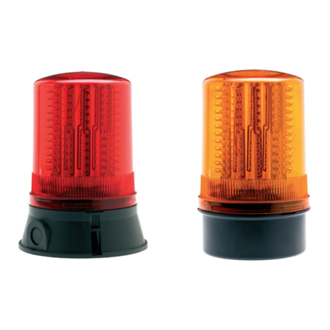
The beacon has 48 extra bright, long life, tri-colour LEDs with 360° visibility and
2 Piezo sounders housed in one compact unit. It is available for 24v dc operation only.
The audible/visual modes may be used independently or combined in any required
combination by PLC control or relays.
Note: The LEDs/Sounders are only ‘ON’ when the SIGNAL is HIGH.
Light Source LEDs Running Current
GREEN 11.2 Effective Candela 250mA
AMBER 8.0 Effective Candela 350mA
RED 6.4 Effective Candela 250mA
Sounder
Frequency 3.1kHz +/- 500Hz
Audibility 90 dBA +/- 3 @ 1Metre 20mA
Supply Requirements
1 Power Input +24v dc
2 Return 0v
3 Signal - Sounder High +24v Low 0v 20mA
4 Signal - Green LED High +24v Low 0v 10mA max
5 Signal - Amber LED High +24v Low 0v 10mA max
6 Signal - Red LED High +24v Low 0v 10mA max
Ingress Protection: IP65 (only if mounted vertically with lens above black base)
Operational Temperature Range: -20 to +450C
Enclosure Materials: UV stable Polycarbonate Lens. UV stable ABS Plastic Base
Suitable Applications: Industrial
Boxed Weight (including dome): 0.33kg
Cable Details
7mm maximum cable diameter.
Maximum 1.5mm2(14 to 22 AWG) stranded core with 4mm cut back.
Optional Equipment
50007 Right Angled Wall Bracket: Use diameter 4mm xings (not supplied).
50003 Cage Guard: Use diameter 5mm xings (supplied).
Note: This guard cannot be used when the Beacon is tted on the Right Angled Wall Bracket.
Spares
50022 Spare Clear Lens Cover.
There are no other user serviceable parts in this unit.
Moash part code S00305 - Issue 4
INSTALLATION &
TECHNICAL INFORMATION
PLEASE READ PRIOR TO INSTALLATION
Website: www.moash.com Email: technical@moash.co.uk
APPROVED AND
CONFORMITIES
LEDA125-01 Series - (LED Tri-colour Beacon)
VISUAL & AUDIBLE COMBINATION SIGNALLING DEVICES
INSTALLATION DATA SHEET
Remove 3 x M3 screws and the base plate from the body.
Pierce the cable grommet.
Insert supply/signal cable (maximum 7mm diameter) through the grommet,
pull back slightly (10mm), for the grommet to form a weatherproof seal.
Connect cable to terminal block.
Terminal Block
No Mode
1 Power Input +24v dc
2 Return 0v
3 Signal - Sounder +24v (high) 0v (low)
4 Signal - Green LED +24v (high) 0v (low)
5 Signal - Amber LED +24v (high) 0v (low)
6 Signal - Red LED +24v (high) 0v (low)
Secure the supply/signal cable to the base with the cable grip.
Replace base plate, ensuring the gasket is in place and aligned to the ‘lead exit position’.
Secure with 3 x M3 screws.
General Installation Notes
• The DC supply must be fully rectied and smoothed. If the supply is used to power
other equipment, particulary inductive loads, additional suppression will be
required. Typical suppression units would be RS 219-2921 or RS 240-696.
• Installation must be carried out, in accordance with latest codes and regulations, by a
qualied electrician.
• Ensure power source is disconnected prior to installation or maintenance to avoid
electric shock.
• Do not handle internal electronic components whilst wiring up.
• Environmental exposure conditions during installation should be dry not
moist or wet conditions.
• The lens material of the beacon is VO rated Polycarbonate UV stable plastic. Do not
clean with petroleum based cleaners.
• The beacon is weatherproof to IP65 only when mounted with the lens uppermost
ie above the black base.
• Use 3 in total, 4mm diameter xings (not supplied) to secure Beacon to its mounting.
• Avoid mounting the beacon where it will be subject to excessive vibration.
Gasket
Terminal Block
(No 1 to 6)
Position of Cable Grip
Cable Grommet Lead Exit Position
Lens
Black Base
SIDE VIEW
OF BEACON
EXTERNAL
UNDERSIDE
VIEW OF BASE
INTERNAL
VIEW OF BASE
3 Holes x 4.5 DIA
on 88 pcd for
mounting
Piezo
Buzzers
11oSide knockout position
4 x 6.5 mm wide
11 mm
Lead exit
position -
5mm max
cable size
27.6
ø98mm
162mm

This manual suits for next models

1

Other MOFLASH SIGNALLING Security System manuals

MOFLASH SIGNALLING R201 Series Manual

MOFLASH SIGNALLING

MOFLASH SIGNALLING R201 Series Manual

MOFLASH SIGNALLING X450 Series Manual

MOFLASH SIGNALLING

MOFLASH SIGNALLING X450 Series Manual

MOFLASH SIGNALLING IS-SB-02 Series Manual

MOFLASH SIGNALLING

MOFLASH SIGNALLING IS-SB-02 Series Manual

MOFLASH SIGNALLING LED201 Series Manual

MOFLASH SIGNALLING

MOFLASH SIGNALLING LED201 Series Manual

Popular Security System manuals by other brands

Feit Electric ALERT/WIFI Important Safety Instructions and Installation Guide

Feit Electric

Feit Electric ALERT/WIFI Important Safety Instructions and Installation Guide

GE Concord express Troubleshooting instructions

GE

GE Concord express Troubleshooting instructions

Ampac FireFinder PLUS Installation, comissioning & operation

Ampac

Ampac FireFinder PLUS Installation, comissioning & operation

Ideal Security SK634 instruction manual

Ideal Security

Ideal Security SK634 instruction manual

Texecom Ricochet Impaq Contact-W user manual

Texecom

Texecom Ricochet Impaq Contact-W user manual

Security Brands RIDGE 2.0 quick start guide

Security Brands

Security Brands RIDGE 2.0 quick start guide

New Cosmos USA ML-310ES user manual

New Cosmos USA

New Cosmos USA ML-310ES user manual

Eaton i-on Series Engineering guide

Eaton

Eaton i-on Series Engineering guide

Conrad UC-AV10 instruction manual

Conrad

Conrad UC-AV10 instruction manual

Pyronix STERLING 10 user guide

Pyronix

Pyronix STERLING 10 user guide

Alarm Lock ALC6-4 operating guide

Alarm Lock

Alarm Lock ALC6-4 operating guide

Logan All in One Series user manual

Logan

Logan All in One Series user manual

ELRO AG400011 quick start guide

ELRO

ELRO AG400011 quick start guide

Teknim VAS 740 F Mounting and User Manual

Teknim

Teknim VAS 740 F Mounting and User Manual

Omega MAX-EDP Operation manual

Omega

Omega MAX-EDP Operation manual

Monacor TVCCD-100PIR instruction manual

Monacor

Monacor TVCCD-100PIR instruction manual

IDS X64 Wireless Training

IDS

IDS X64 Wireless Training

Bellman BE1010 manual

Bellman

Bellman BE1010 manual

manuals.online logo
manuals.online logoBrands
  • About & Mission
  • Contact us
  • Privacy Policy
  • Terms and Conditions

Copyright 2025 Manuals.Online. All Rights Reserved.