manuals.online logo
Brands
  1. Home
  2. •
  3. Brands
  4. •
  5. MOFLASH SIGNALLING
  6. •
  7. Security System
  8. •
  9. MOFLASH SIGNALLING LED201 Series Manual

MOFLASH SIGNALLING LED201 Series Manual

INSTALLATION &
TECHNICAL INFORMATION
PLEASE READ PRIOR TO INSTALLATION
Website: www.moash.com Email: technical@moash.co.uk
APPROVALS AND
CONFORMITIES
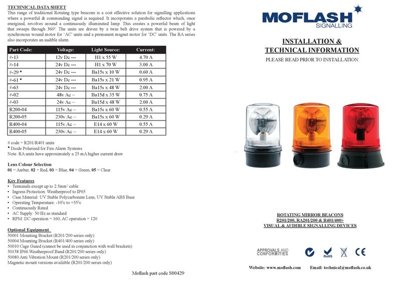
TECHNICAL DATA SHEET
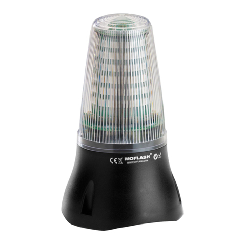
This range of beacons incorporates a 144 o LED array that emits its light through 360o
around the vertical axis. They have a choice of four modes of alarm that are pre-set via a
two-way dip switch located under the lens. To maintain the ingress protection of the enclosure the
lens should always be mounted above the base. The 201/200 series is suitable for surface, conduit
box or wall mounting. The LED401/400 is suitable for surface or wall mounting.
For Lens colours add: -01 Amber, -02 Red, -03 Blue, -04 Green, -05 Clear
Key Features Include:
Note: The 201/200 series has the ability to be used in a ‘loop in’ ‘loop out’ daisy chain
application using the terminals provided, however the wire size must not exceed 2.5mm2.
• Connection terminals except upto 2.5mm2 cable
• Multi Voltage high volt options
• Operating Temperature -25oc to +55oc
• Case Material is UV Stable Polycarbonate & UV Stable ABS
• Weatherproof to IP65
• AC = 50/60 Hz
Optional Equipment:
• 50004 Mounting Bracket
• 50010 Cage Guard (cannot be used in conjunction with mounting bracket)
• 50080 Anti Vibration Mount (201/200 Series)
Moash part code S00418 Issue 3
LED201/200 & LED401/400 Series - (LED Array)
MULTI-FUNCTIONAL VISUAL SIGNALLING DEVICES
Part Code: Voltage: Colours Current:
Flashing Rotating Static
LED201-02 24v Dc --- Red & Amber 210mA 130mA 440mA
Green, Blue & Clear 115mA 50mA 230mA
LED200-04 •90-370v Dc ---
70-265v Ac ~
Red & Amber 110/55mA 50/25mA 200/100mA
Green, Blue & Clear 65/40mA 27/20mA 120/59mA
LED401-02 24v Dc --- Red & Amber 210mA 130mA 440mA
Green, Blue & Clear 115mA 50mA 230mA
LED400-04 •90-370v Dc ---
70-265v Ac ~
Red & Amber 110/55mA 50/25mA 200/100mA
Green, Blue & Clear 65/40mA 27/20mA 120/59mA
• Current @ 115/230v Ac ~
• Current @ 280v Dc ---
Amber/Red in Static Mode is 40mA
All Models Pre-set to Flash Mode
2 Bar Rotating
PICTURE 1
Terminal Connections
INSTALLATION DATA SHEET
LED201/200 Series
Carefully twist lens rmly one turn clockwise to remove from base. Remove 3 x No:4 screws
from LED mounting plate that x plate to internal lugs in the base. Fix base to the required
surface, utilising rubber gasket, with 2 x M4 screws (not supplied). Insert power cable through
aperture in base & connect to the 4 way terminal on the PCB. ‘see picture 1’. Position the base of the
LED array over the internal base lugs & x in place with 3 x No:4 screws.
LED401/400 Series
Connection to this type of unit is either into the three way barrier strip situated in the base of the
unit (standard connection) or via the M20 side conduit entry. If M20 is preferred method then two
wires in the barrier strip in the base need to be unscrewed and freed from the barrier strip. Un-screw
3 x No:4 screws that retain the base plate & carefully remove, threading the wires through the aperture.
Un-screw the same two wires from the internal terminal block. Carefully drill out the M20 entry &
using the appropriate cable gland, insert power cable into unit connecting to the internal terminal block.
Screw base plate back into position. Fix base to the required surface using the supplied gasket with
3 x M6 Hex set screws (not supplied).
Alarm Stages (Modes of Operation)
These are selected by a two way dip switch on the lens side of the PCB at installation.
The operational mode is factory pre-set to FLASH.
Replace lens onto base ensuring that the base spigot ‘O’ ring is in place. Twist lens one turn
anti-clockwise to lock & check that the ‘O’ ring is positioned correctly & not caught or snagged.
General Installation Notes
• Installation must be carried out in accordance with the latest codes of practice by
a qualied electrician.
• Ensure power is disconnected prior to installation or maintenance to avoid electrical shock.
• Environmental exposure conditions during installation should be dry, not moist or wet.
• The lens of the unit is polycarbonate plastic. Do not clean with petroleum based cleaners.
• To maintain the IP65 weatherproof rating the beacon must be mounted with
the lens above the base.
• Avoid mounting the beacon where it will be subject to excessive vibration.
LED201/200 Series LED401/400 Series
ON
1 2
STEADY 1 BAR ROTATING FLASH 2 BAR ROTATING
SWITCH
POSITION
ON ON ON
1 2 1 2 1 2 +V (L) Power In Ov (N)

This manual suits for next models

7

Other MOFLASH SIGNALLING Security System manuals

MOFLASH SIGNALLING R201 Series Manual

MOFLASH SIGNALLING

MOFLASH SIGNALLING R201 Series Manual

MOFLASH SIGNALLING LEDA125-01 Series Manual

MOFLASH SIGNALLING

MOFLASH SIGNALLING LEDA125-01 Series Manual

MOFLASH SIGNALLING X450 Series Manual

MOFLASH SIGNALLING

MOFLASH SIGNALLING X450 Series Manual

MOFLASH SIGNALLING IS-SB-02 Series Manual

MOFLASH SIGNALLING

MOFLASH SIGNALLING IS-SB-02 Series Manual

Popular Security System manuals by other brands

MetaSystem EasyCan Digital Installation instruction

MetaSystem

MetaSystem EasyCan Digital Installation instruction

SAFE HOME PT700 user manual

SAFE HOME

SAFE HOME PT700 user manual

foc.us FC-7564 user manual

foc.us

foc.us FC-7564 user manual

Abus TVAC15000 user manual

Abus

Abus TVAC15000 user manual

Abus Smartvest FUSG35000A manual

Abus

Abus Smartvest FUSG35000A manual

Scantronic 8136UK-50 Installation and user guide

Scantronic

Scantronic 8136UK-50 Installation and user guide

foc.us ST-IIIB manual

foc.us

foc.us ST-IIIB manual

Paradox ESPRIT 728 ULT Programming guide

Paradox

Paradox ESPRIT 728 ULT Programming guide

Security Command Command Processor XR6 user guide

Security Command

Security Command Command Processor XR6 user guide

Abus Secves FU8007 quick start guide

Abus

Abus Secves FU8007 quick start guide

Homeguard LS100 user manual

Homeguard

Homeguard LS100 user manual

Storage Options CCTV SECURITY SYSTEM instruction manual

Storage Options

Storage Options CCTV SECURITY SYSTEM instruction manual

Easy@Home IN03E instruction sheet

Easy@Home

Easy@Home IN03E instruction sheet

Q-See QC40196-833 Quick installation guide

Q-See

Q-See QC40196-833 Quick installation guide

Innohome SA102RF user manual

Innohome

Innohome SA102RF user manual

BigDog BD50 Series user manual

BigDog

BigDog BD50 Series user manual

Security Command XR20 Executive Series user guide

Security Command

Security Command XR20 Executive Series user guide

basIP SH-45TE user manual

basIP

basIP SH-45TE user manual

manuals.online logo
manuals.online logoBrands
  • About & Mission
  • Contact us
  • Privacy Policy
  • Terms and Conditions

Copyright 2025 Manuals.Online. All Rights Reserved.