MOLEAER KINGFISHER User manual

MOLEAER KINGFISHER
NANOBUBBLE GENERATOR
Owner’s Manual
IMPORTANT: READ, FOLLOW AND
SAVE THESE INSTRUCTIONS
CUSTOMER SERVICE / TECHNICAL SUPPORT
If you have questions or need to order
replacement parts, please contact:
CUSTOMER SERVICE:
Monday to Friday: 8:00 a.m. to 5:00 p.m. PST
Phone: +1 (424) 558-3567
WEBSITE:
www.moleaer.com

MOLEAER KINGFISHER
NANOBUBBLE GENERATOR
Owner’s Manual
www.moleaer.com CONFIDENTIALi
Table of Contents
Safety...................................................................................................................................................................................... 2
General Warnings ............................................................................................................................................................... 2
General Information .............................................................................................................................................................. 3
Key System Components.................................................................................................................................................... 3
Quick Startup Guide ............................................................................................................................................................. 4
Suction and Discharge Verification ..................................................................................................................................... 4
Typical Operating Parameter Ranges................................................................................................................................. 4
Specifications ........................................................................................................................................................................ 4
Power Input Requirements.................................................................................................................................................. 5
Gas Connection................................................................................................................................................................... 5
Technical Specs .................................................................................................................................................................. 5
Piping Specifications ........................................................................................................................................................... 5
Pump Specifications............................................................................................................................................................ 5
Installation & Startup ............................................................................................................................................................ 6
Parts and Accessories......................................................................................................................................................... 6
Drawings ................................................................................................................................................................................ 7
Pipe Assembly..................................................................................................................................................................... 8
Ozone Bypass ..................................................................................................................................................................... 9
Startup................................................................................................................................................................................. 9
Maintenance........................................................................................................................................................................... 9
Pump Maintenance ........................................................................................................................................................... 10
General Arrangement Drawing (GAD)............................................................................................................................... 12
Solvent Welding PVC Pipe ................................................................................................................................................. 13
Cleaning and Sanitizing...................................................................................................................................................... 14
Operation Checklist ............................................................................................................................................................ 16
Preventive Maintenance Checklist .................................................................................................................................... 17
Troubleshooting Guide....................................................................................................................................................... 18
Limited Warranty................................................................................................................................................................. 20

MOLEAER KINGFISHER
NANOBUBBLE GENERATOR
Owner’s Manual
www.moleaer.com CONFIDENTIAL 2
Safety
This guide provides
operation and
maintenance instructions for this product.
Consult Moleaer with any questions
regarding this equipment.
The Kingfisher unit is designed to deliver a micro-dose of
Ozone nanobubbles to the waterbody. Depending on the
local
regulations and restrictions, customers may be
required to bypass the Ozone system. Please review the
manual to bypass ozone generation if needed.
Attention Installer
This guide contains important information about the
operation, maintenance, and safe use of this product. This
information should be given to the owner and/or operator of
this equipment after installation.
Attention User
This manual contains important information that will help
you in operating and maintaining this product. Please retain
it for future reference.
READ AND FOLLOW ALL INSTRUCTIONS.
This is the safety alert symbol. When you
see this symbol on your system or in this
manual, look for one of the following
signal words and be alert for potential
injuries.
Warns about hazards that can cause
death, serious personal injury, or major
property damage if ignored.
Warns about hazards that may or can
cause minor personal injury or property
damage if ignored.
NOTE Indicates special instructions not related
to hazards. Carefully read and follow all
safety instructions in this manual and on
equipment. Keep safety labels in good
condition; replace labels i
f missing or
damaged.
When installing and using this electrical equipment, basic
safety precautions should always be followed.
Risk of Electrical Shock
Connect only to a branch circuit protected by a ground fault
circuit interrupter (GFCI). Contact a qualified electrician if
you cannot verify that the circuit is protected by a GFCI.
General Warnings
Never open the inside of the pump motor enclosure. There
is a capacitor bank that holds an electrical charge even
when there is no power to the unit.
Code requirements for the electrical connection differ from
location to location. Install equipment following all
applicable local codes and ordinances.
Before servicing the pump, remove power from the system
by unplugging the unit from the outlet.
This equipment is not intended for use by persons
(including children) with reduced physical, sensory or
mental capabilities, or lack of experience and knowledge
unless they have been given supervision or instruction
concerning the use of the appliance by a person
responsible for their safety.
RISK OF ELECTRICAL SHOCK. INSTALLERS,
OPERATORS, AND OWNERS MUST READ
THESE WARNINGS AND ALL THE
INSTRUCTIONS IN THE OWNER’S MANUAL
BEFORE USING THIS UNIT. THESE WARNINGS
AND THE OWNER’S MANUAL MUST BE LEFT
WITH THE PRODUCT OWNER.
Suction Entrapment Hazard
Stay off the main drain and away from all suction outlets!
This generator produces high levels of suction and creates
a strong vacuum at the main drain (located at the bottom of
the body of water). This suction is strong enough to trap
adults or children underwater if they come in close proximity
to a drain, a loose or broken drain cover, or a grate.
NOTE: All suction plumbing must be installed in accordance
with the latest national and local codes, standards, and
guidelines.

MOLEAER KINGFISHER
NANOBUBBLE GENERATOR
Owner’s Manual
www.moleaer.com CONFIDENTIAL 3
Install all electrical equipment, such as ON / OFF
switches, timers, and control systems, etc. to allow
the operation (startup, shutdown, or servicing) of
any pump or filter so the user does not place any
portion of his / her body over or near the pump
str
ainer lid, filter lid, or valve closures. This
installation should allow the user enough space to
stand clear of the filter and pump during system
startup, shutdown or servicing of the system filter.
Hazardous pressure. Stand clear of pump and filter
during startup. Circulation systems operate under
pressure, when servicing any part of the system, air
can enter the system and become pressurized.
Pressurized air can cause any part of the pump, filter
or valves to violently separate which can result in
severe personal injury. Filter lid must be properly
secured to prevent separation. Stand clear of all
circulation system equipment when starting pump.
Before servicing equipment make note of system
pressure before opening filter basket.
General Information
Read instructions thoroughly prior to installation and use.
All Kingfisher products are factory adjusted for optimal
nanobubble production. Note that the actual unit sold
may differ slightly from the description in the manual without
any difference in the functionality and performance of the
unit.
Increasing DO levels increases the aerobic conditions in
water, promoting beneficial bacteria that digest sediment
muck, improve water clarity, and enhance the aquatic
ecosystem to help foster clearer, healthier water bodies.
The Moleaer Kingfisher product is a nanobubble gas-
injection technology tailormade for the hard-to-treat water
bodies like golf course ponds and waterways, HOA and
condo lakes and ponds or even residential lakefronts and
small irrigation reservoirs. Its principal function is to improve
the quality of water by increasing the aerobic conditions in
water body, promoting beneficial bacterial that digest
sediment muck, improve water clarity, and enhance aquatic
ecosystem. With simplicity and near-perfect efficiency, the
Kingfisher nanobubble generator super saturates water
with dissolved oxygen and trillions of negatively charged
nanobubbles. These tiny bubbles, about 100x smaller than
a red blood cell, have several unique physical properties
that make them behave differently from normal bubbles.
Nanobubbles are neutrally buoyant and remain stable in
solution for prolonged periods of time, creating a healthier
water body.
Key System Components
Figure 1. Kingfisher Weather-Proof Steel Cabinet
1. Cabinet
2. On/Off indicator light
3. Cooling air discharge
4. Water pump inlet
5. Water pump outlet
Figure 2. Kingfisher Pump & Piping
1. 1.5HP self-priming pump with strainer basket
2. Water Inlet
3. Nanobubble generator
4. Gas injection fitting
5. Check valve

MOLEAER KINGFISHER
NANOBUBBLE GENERATOR
Owner’s Manual
www.moleaer.com CONFIDENTIAL 4
Figure 3. Kingfisher Panel
1. Electrical box
2. Water pressure gauge
3. Gas pressure gauge
4. Compressor
5. Ozone Generator
Quick Startup Guide
1. Review detailed location and piping installations
prior to installing the Kingfisher unit.
2. Open the lid of the Kingfisher and hand-tighten any
loose fittings.
3. Plug the unit power cord into the GFCI outlet.
4. Loosen the strainer basket lid from the pump by
turning it counterclockwise.
5. Using a bucket, prefill the pump basket with
approximately one gallon of water.
6. When the pump strainer fills with water, tighten the
pump strainer basket lid by turning the lid
clockwise.
7. Turn the Kingfisher on by pushing the start button.
8. Check that water is flowing through the pump by
verifying that the strainer basket is filled with water.
If the pump does not prime after several minutes, turn the
Kingfisher off, review all suction pipe field connections to
ensure airtight connections, all valves are open, and try
again. Wait five minutes before re-priming to allow the
pump seals to cool.
Once primed, large bubbles or a large air pocket should not
be visible in the strainer basket. Any visible large bubbles
or an air pocket in the strainer basket is an indication of a
suction pipe leak. Check suction pipe for leaks and ensure
all pipe connections are airtight.
Once the pump is primed and the system is pumping water,
visually check for leaks inside the unit and hand tighten any
fittings that may be leaking, if hand tightening doesn’t stop
leaks, shut the unit down, close any isolation valves, and
disassemble the connections to inspect for any pinched O-
rings and that pipes are aligned properly and reassemble.
Suction and Discharge Verification
Observe the suction and discharge locations in the
waterbody. The intake should not create a vortex at the
surface. If a vortex is visible, the intake screen is not
properly submerged. Verify that the intake screen is resting
on the floor of the waterbody and extend the suction pipe
as required to position the intake screen in a deeper
location of the waterbody. The bubble pattern visible at the
surface of the water above the discharge should consist
primarily of small bubbles, roughly the size of a pea or
smaller.
Typical Operating Parameter Ranges
The typical operating parameter ranges for the Kingfisher
are shown in Table 1.
Table 1. Kingfisher Typical Operating Parameter Ranges
Parameter Kingfisher
Gas Pressure (Gauge) 10 –20 psig (0.7 – 1.4 barg)
Liquid Pressure (Gauge) 10 –20 psig (0.7 – 1.4 barg)
Specifications
Failure to install the Kingfisher within the limits
specified in these specifications may void the
system warranty and result in poor nanobubble
production and pump cavitation.

MOLEAER KINGFISHER
NANOBUBBLE GENERATOR
Owner’s Manual
www.moleaer.com CONFIDENTIAL 5
Power Input Requirements
Table 2. Kingfisher Power Input Requirements
60 Hz (North America) Single Phase, 115 VAC
50 Hz Single Phase, 230 VAC
Pipe lengths and unit elevations can play an important role
in the performance of the pump. Refer to the Appendix for
additional detail regarding the recommended operating
envelope for this unit.
Gas Connection
Moleaer Kingfisher generators come with an air
compressor that feeds into a (40 mg/hr) micro-dose ozone
generator. Depending on the local restrictions, the ozone
generator can be bypassed as described in this manual.
Technical Specs
Table 3. Kingfisher Technical Specifications
Temperature Tolerance, F 40-140
Solids, inches <3/8
Voltage 120
Phase 1
Running Amps (Standard
Household 15 Amp Outlet) 8.2
Piping Specifications
Table 4. Kingfisher Piping Specifications
Nominal Pipe Size 1.5 in (63 mm)
Maximum Suction Pipe Length 20 feet/6 meters
Maximum Total Pipe Length
(Suction + Discharge) 40 feet/12 meters
Recommended maximum
Suction Lift
6 feet (2 m) above
water surface
Pump Specifications
Table 5. Kingfisher Pump Specifications
Equipped Pump Brand:
Anbull SP-1100A or
equivalent
Power 1.5 HP / 1.1 kW
Start Amperage 11.5 A
Voltage 115/230 VAC
Hertz 50/60 Hz
Capacitor 50 μF/250V
Flow Rate 40 GPM / 9.2 m3/h
Head 50 ft / 15.5 m
Temperature (Max) 120˚F / 50C˚

MOLEAER KINGFISHER
NANOBUBBLE GENERATOR
Owner’s Manual
www.moleaer.com CONFIDENTIAL 6
Installation & Startup
Customers are responsible for meeting all installation
guidelines recommended in this section.
Upon delivery, unbox and inspect the Kingfisher for any
damage or loose parts that may have occurred during
transport. Hand-tighten any loose unions.
Parts and Accessories
The parts and accessories shown in Table 6 are shipped
loose with all Kingfisher products.
Included Accessories
Table 6. Kingfisher Accessories
Image Line
Item
QTY KINGFISHER
1 1 Suction Strainer
2 1 CIP Tool
3 1 Pump Union
4 2 Pump Union O-Ring
5 1 Pipe Union
6 1 Basket Strainer O-Ring
7 1 Cabinet Keys
Image Line
Item
QTY KINGFISHER
8 1 Quick Start Guide
Location Requirements
The guidelines herein are recommended for calm water
bodies with intake structure depths less than 10 ft (3 m).
The unique site conditions for each site should be carefully
considered when identifying the Kingfisher installation
location. Carefully select the installation location based on
the requirements specified in this section. Locate the
Kingfisher as close to the waterbody as possible in an open
area of level ground. Use the guidelines shown in Figures
4 and 5 to locate the suction screen. We recommend that
the unit be located no higher than 6’ (2 m) above the water
surface. Ensure that the suction screen location is free of
weeds and debris. Do not locate the suction screen in an
area where leaves or other floatable debris tend to
accumulate.

MOLEAER KINGFISHER
NANOBUBBLE GENERATOR
Owner’s Manual
www.moleaer.com CONFIDENTIAL 7
Drawings
Figure 4: Kingfisher Installation Diagram
Figure 5: Kingfisher Installation Diagram from Top

MOLEAER KINGFISHER
NANOBUBBLE GENERATOR
Owner’s Manual
www.moleaer.com CONFIDENTIAL 8
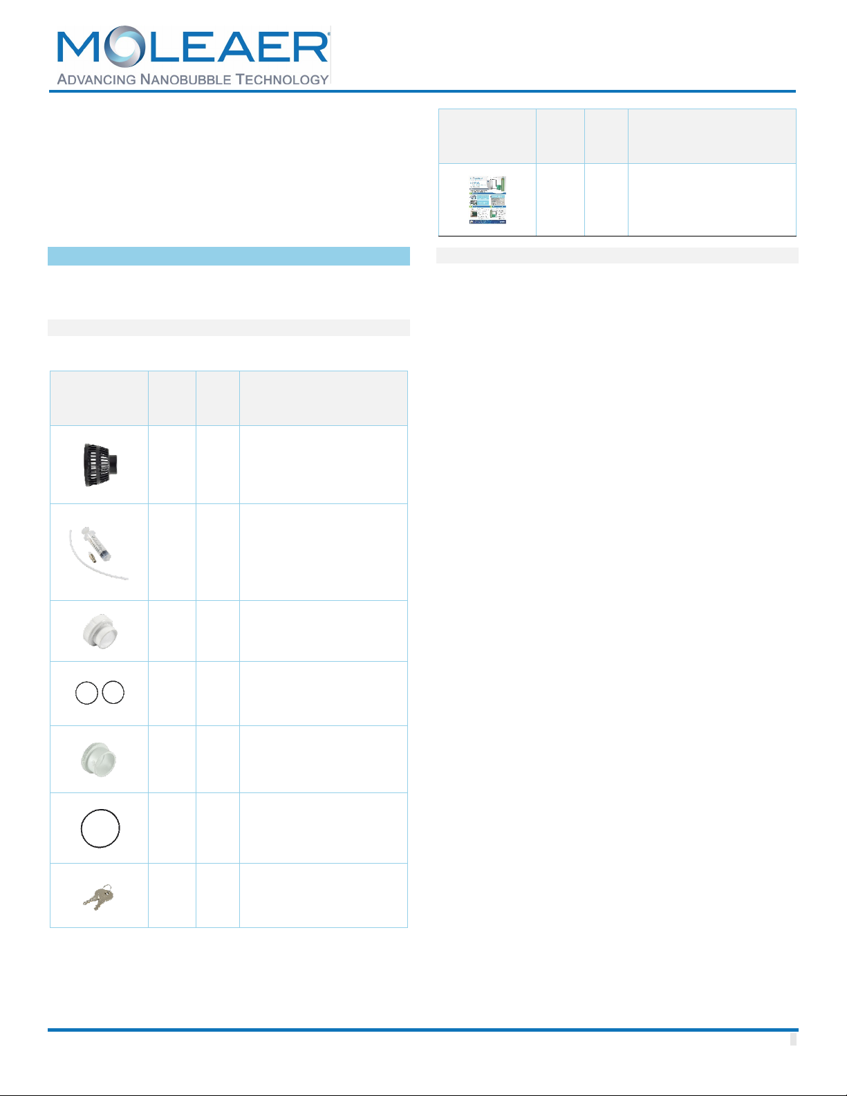
Parts, Tools, and Materials
The following is a list of various parts, materials and tools
required for the installation and startup of the equipment.
As each installation is unique, this is not an exhaustive but
a recommended list.
•PVC Glue
•PVC saw
•PVC pipe primer and PVC pipe cement
•PVC Pipe or hose and fittings to connect to the
tank.
•Wrench
•Pliers
•Level
•Smoke pen for checking leaks on the suction line
•Spray bottle of soapy water for detecting air tube
leaks
•Miscellaneous items including tape measure,
marking pencil, shop towels for cleaning, etc.
Pipe Assembly
Completely bury or submerge all PVC pipes and fittings to
avoid ultraviolet (UV) degradation. All PVC pipe
connections must be solvent welded using PVC cement.
Use only Schedule 40 polyvinyl chloride (PVC) pipe and
fittings. Use only PVC cement formulated for wet conditions
and fast installation to connect PVC pipe to PVC fittings. Do
not use black, acrylonitrile butadiene styrene (ABS) piping
or mix ABS pipe or fittings with PVC pipe or fittings.
All PVC pipe connections must be airtight and leakproof.
Failure to provide airtight suction pipe connections may
negatively impact nanobubble generator performance.
Large bubbles visible at the pump strainer basket are an
indication of suction pipe leaks. Difficulty with pump priming
may also be an indication of suction pipe leaks. Check and
correct for all suction and discharge pipe leaks prior to
burying or submerging the pipe.
Proper technique must be used when gluing PVC pipe and
fittings to ensure an airtight, leakproof connection. For
proper technique, refer to the Appendix. Allow for proper
cure time before wet testing suction and discharge pipes.
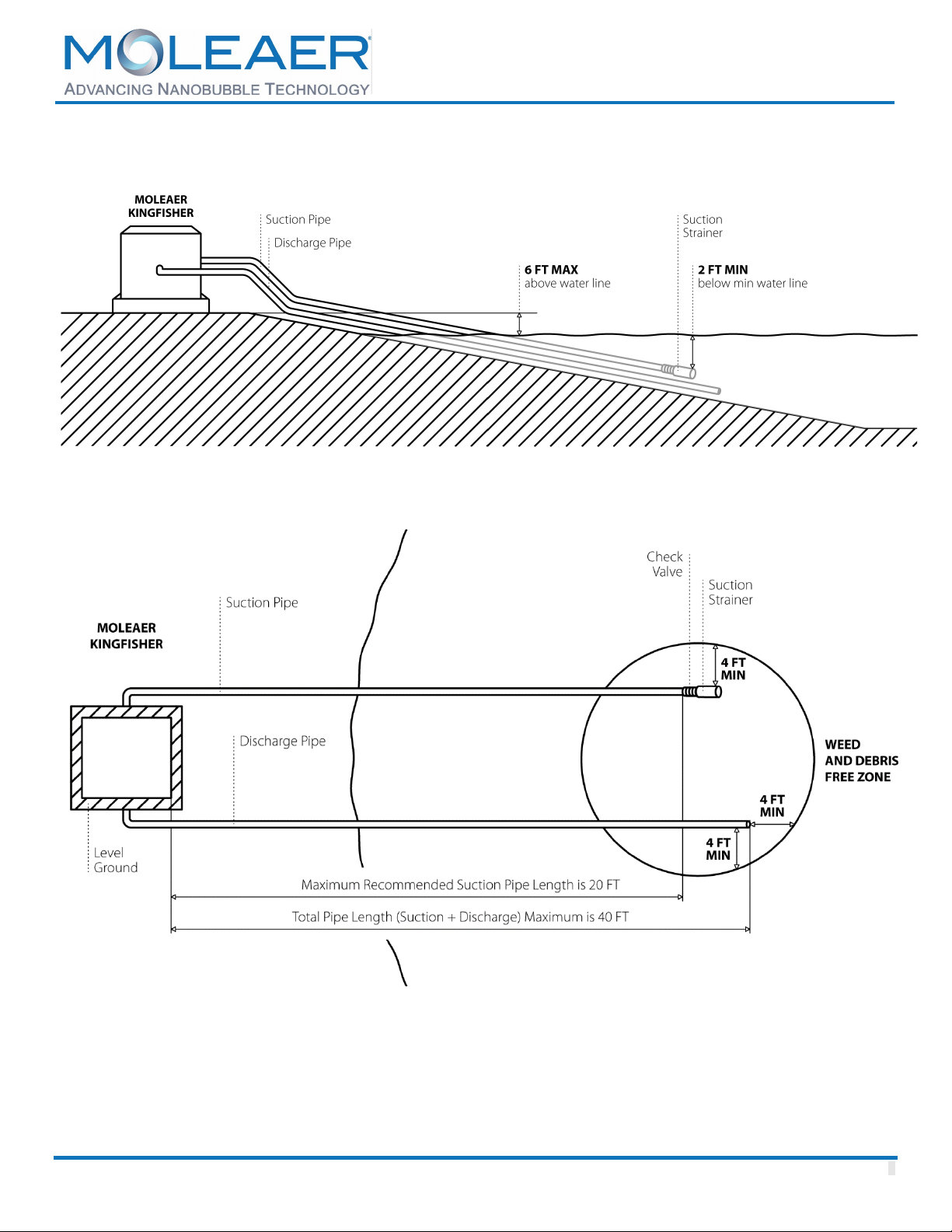
Piping
Pipe lengths and unit elevation can play an important role
in the performance of the unit. Standard Installation should
be no higher than 6’ above the water surface, and the total
length of pipe above the water surface should be less than
10’, but in no case longer than 30’. In this Standard
Installation, priming of the pump is expected to require no
more than 5 minutes if there are 10’ of pipe above the water
surface, and will be considerably longer if the length of pipe
above the water surface is between 10' and 30’ in length.
Locate and install the discharge pipe following the
recommendations detailed in Figures 4 and 5.
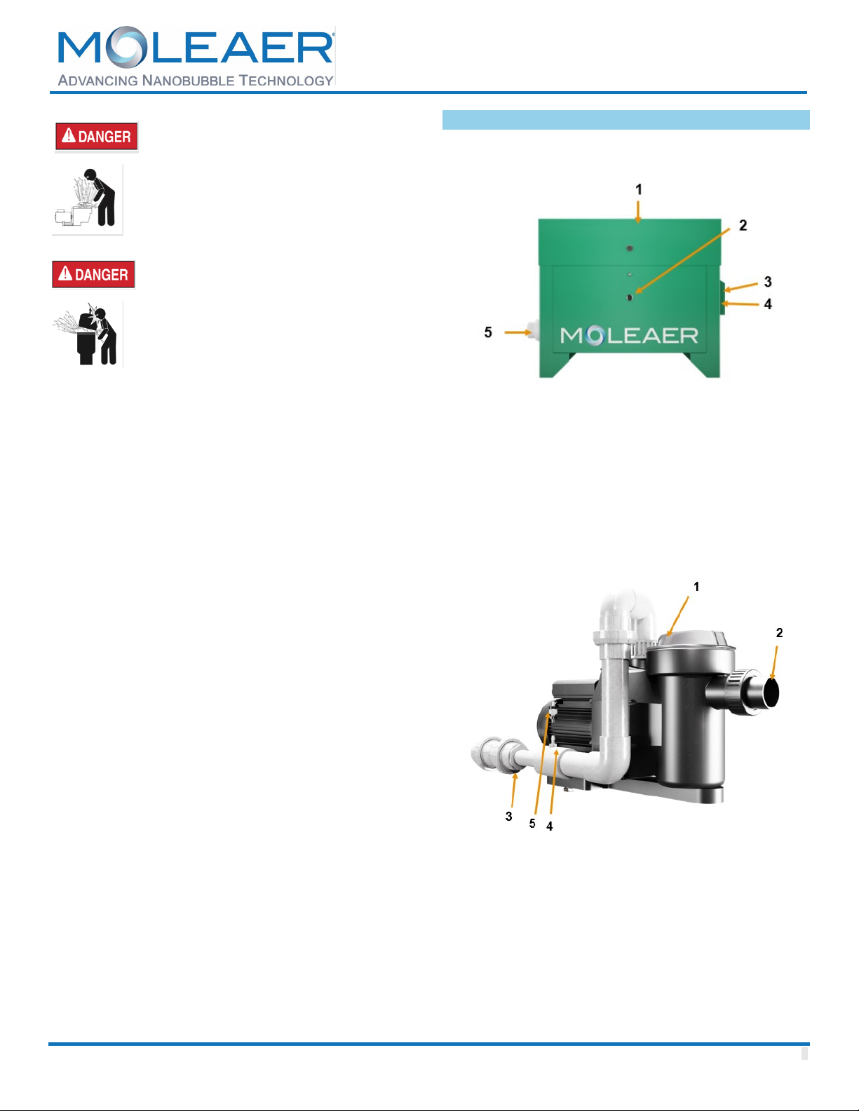
The intake and discharge ports on the Kingfisher are both
1.5” (63 mm) union fittings.
Locate and install the intake structure and suction pipe
following the recommendations detailed in Figures 4 and 5.
Use available fittings as necessary to route the suction
piping from the unit to the waterbody. Do not remove the
bell end of the PVC pipe. The bell end can be used as a
coupling for connecting straight pipe segments.
Install the included intake screen at the suction end of the
pipe to stop large debris from entering the system. Ensure
that the intake screen is fully submerged but elevated from
the lake bottom to avoid sediment buildup. Ensure that the
suction line is continuously rising from the water body to the
inlet of the unit. High spots in the suction line may trap air
and prevent the pump from self-priming properly.
It is recommended to install a swing-style check valve to
facilitate faster priming of the pump during start-up. If a
check valve (not included) is installed on the suction line,
ensure that it is installed with the flow arrow in the direction
of suction flow so as not to restrict the flow of water to the
pump.
Locate and install the discharge pipe following the
recommendations detailed in Figures 1 and 2. Use
available fittings as necessary to route the discharge piping
from the unit to the waterbody. Discharge should be firmly
fixed and pointed towards the center of the water body to
avoid causing erosion. Do not remove the bell end of the
PVC pipe. The bell end can be used as a coupling for
connecting straight pipe segments.
Do not bury either suction or discharge pipe until the system
has been wet tested and is free of leaks.
Power Input
Extension cord use is hazardous and should be
avoided. In certain jurisdictions, permanent
installation using an extension cord is not
permitted. Check with your local electrical code.
Step 1. The Kingfisher requires a dedicated, weather-
resistant power receptacle. After starting the Kingfisher,
perform a voltage drop test to verify voltage is within normal
limits.

MOLEAER KINGFISHER
NANOBUBBLE GENERATOR
Owner’s Manual
www.moleaer.com CONFIDENTIAL 9
Step 2. When all piping is installed, cure time has been
met, and proper circuit operation has been verified, you are
ready to start up the normal operation of the Kingfisher.
Ozone Bypass
The Moleaer Kingfisher nanobubble generator comes
factory installed with a (40 mg/hr) micro-dose ozone
generated. In some locations, local regulations may
prohibit the use of any ozone in the waterbody.This section
describes the method(s) to bypass ozone and just use
ambient air for nanobubble generation.
The ozone generator must be disconnected from the inside
of the electrical box.
1. Power down the unit.
2. Trace the ozone generator wires back to the
electrical box.
3. Using a flat-head screwdriver, loosen the screws
on the corresponding terminal blocks and pull out
the ozone generator wires as shown in Figure 6.
4. Loosen the cord grip on the box and pull out the
ozone generator cable.
5. Tighten the cord grip.
6. The ozone generator (the green LED light) should
now be off. It is not required to change the tubing.
The air flows from the compressor and into the
nanobubble generator via the ozone system
without generating any ozone.
Startup
1. Remove the pump basket lid by rotating anticlockwise.
2. Using a bucket, prefill the pump basket with
approximately one gallon of water.
3. Reinstall the basket lid, until it is hand tight.
4. Plug the unit power cord into the outlet.
5. Push start switch to start system.
6. Wait until the pump basket fills with water, which can
take up to five minutes.
A hose or bucket can be used to fill the suction line between
the check valve and pump for systems that are difficult to
prime. Fill the pump basket until the suction line fills
completely and begins to fill the pump basket to the top.
Pump priming may take several minutes. If the pump does
not prime after several minutes, turn the unit off, review all
suction pipe field connections to ensure airtight
connections, re-prime the pump and try again. Wait five
minutes before re-priming to allow the pump seals to cool.
Once primed, large bubbles or a large air pocket should not
be visible in the strainer basket. If large bubbles or an air
pocket are visible in the strainer basket there is a suction
pipe leak. Check suction pipe for leaks and ensure all pipe
connections are airtight. Consider installing a swing-style
check valve to stop the draining of water from the suction
pipe.
Observe the suction and discharge locations in the
waterbody. The intake should not create a vortex at the
surface. If a vortex is visible, the intake screen is not
properly submerged. Verify that the intake screen is resting
on the floor of the waterbody and extend the suction pipe
as required to position the intake screen in a deeper
location of the waterbody. The bubble pattern visible at the
surface of the water above the discharge should consist
primarily of small bubbles, roughly the size of a pea or
smaller.
NOTE:
1. If the pond or lake does not have an existing
aeration system, the nanobubble generator should
initially be run periodically over the first seven
days of treatment to avoid an overabundance of
bacteria causing a decline in dissolved oxygen
from de-stratifying of the lake.
2. Expect to see algae float to the surface within the
first few weeks. This is normal. It may foul the
intake screen during this period; therefore,
periodic inspections are necessary until the algae
float has subsided.
Maintenance
Intake screens should be cleaned periodically, along with
the pump basket. Inspect the intake multiple times per week
during the first month of operation and every three weeks
thereafter.
A drop in water pressure is most likely the result of a
clogged intake or check valve (if installed). If a drop in
water pressure is observed, inspect the intake and
check valve.
Moleaer recommends monthly inspection (see Operation
Checklist in this manual) followed by quarterly cleanings of
intake screens and piping.
The gas injection zone (nanobubble generator) may require
periodic cleaning due to biofouling inside the piping. If the
gas pressure gauge is above 20 Psi and the visible bubbles
from the discharge pipe are significantly reduced a cleaning
is necessary. Refer to the clean-in-place procedure for
more information.

MOLEAER KINGFISHER
NANOBUBBLE GENERATOR
Owner’s Manual
www.moleaer.com CONFIDENTIAL 10
Pump Maintenance
Do NOT open the strainer basket if pump fails to
prime, or if pump has been operating without water
in the strainer pot. Pumps operated in these
circumstances may experience a buildup of vapor
pressure and may contain scalding hot water.
O
pening the pump may cause serious personal
injury. To avoid the possibility of personal injury,
make sure the suction and discharge valves are
open and strainer pot temperature is cool to touch,
then open with extreme caution. To prevent damage
to the pump and for proper operation of the system,
clean pump strainer and system every two weeks.
To prevent damage to the pump and for proper
operation of the system, clean pump strainer and
system regularly.
Pump Strainer Basket Care
The strainer basket must be kept clean and free of debris.
Inspect the basket through the lid on the top of the housing.
Be sure to visually inspect the strainer basket regularly.
Dirty strainer baskets reduce filter efficiency and put
abnormal stress on the pump motor. Bacterial fouling could
cause the lid not to be clear.
Cleaning the Pump Strainer Basket
1. Flip the switch to the OFF position and confirm the
red light turns on.
2. Relieve pressure in the system.
3. Close system isolation valves
4. Turn the lid counterclockwise and remove it from
the pump.
5. Remove debris and rinse out the basket.
6. Put the basket back into the housing. Be sure to
align the notch in the bottom of the basket with the
rib in the bottom of the housing.
7. Fill the pump basket up to the inlet port with water.
8. Clean the lid and clamp, O-ring, and sealing
surface of the pump basket.
NOTE: It is important to keep the lid O-ring clean and
well lubricated.
Figure 7. Pump Specifications
9. Reinstall the lid by placing the lid on the basket. Be
sure the lid O-ring is properly placed. Seat the lid
on the pump then turn clockwise until tight.
10. Press the switch to the ON position. Confirm the
green light turns on.
11. Wait until a steady water flow is observable through
the pump basket lid.

MOLEAER KINGFISHER
NANOBUBBLE GENERATOR
Owner’s Manual
www.moleaer.com CONFIDENTIAL 11
Winterizing
In mild climate areas, when temporary freezing conditions
may occur, run your equipment all night to prevent freezing.
You are responsible for determining when freezing
conditions may occur. If freezing conditions are expected,
take the following steps to reduce the risk of freeze
damage. Freeze damage is not covered under warranty.
To prevent freeze damage, follow the procedures below:
1. Shut off electrical power for the pump at the circuit
breaker.
2. Drain the water out of the pump housing by
removing the one twist drain plug from the housing.
Store the plug in the pump basket.
NOTE: Do not wrap the motor with plastic or other airtight
materials during winter storage. The motor may be covered
during a storm, winter storage, etc., but never when
operating or expecting operation.
Figure 8. Pump Head Curve
PUMP SERVICE
Always disconnect power to the Kingfisher generator
and / or pump at the circuit breaker before servicing
the pump. Failure to do so could result in death or
serious injury to service people, users or others due
to electric shock. Read all servicing instructions
before working on the pump.
Do NOT open the strainer basket if pump fails to
prime or if pump has been operating without water in
the strainer basket
. Pumps operated in these
circumstances may experience a build-up of vapor
pressure and may conta
in scalding hot water.
Opening the pump may cause serious personal
injury. In order to avoid the possibility of personal
injury, make sure the suction and discharge valves
are open and strainer basket temperature is cool to
touch, then open with extreme caution.
Be sure not to scratch or mar the polished shaft seal
faces; seal will leak if faces are damaged. The
polished and lapped faces of the seal could be
damaged if not handled with care.
Motor Care
Protect from Heat
Do not block the fan intake and the louvers. Provide ample
space around the unit to allow free airflow. This is normally
accomplished by giving about 2 feet (0.5 meters) easement
around the cabinet.
Protect Against Dirt
1. Protect from any foreign matter or splashing water.
2. Do not store (or spill) chemicals on or near the
motor.
3. Protect from any foreign matter or splashing water.
4. Avoid sweeping or stirring up dust near the motor
while it is operating.
5. If a motor has been damaged by dirt it voids the
motor warranty.
6. Clean the lid and clamp, O-ring, and sealing
surface of the pump basket.
Protect Against Moisture
1. If a motor has become wet, let it dry before
operating. Do not allow the pump to operate if it has
been flooded.
2. If a motor has been damaged by water the motor
warranty is voided.

MOLEAER KINGFISHER
NANOBUBBLE GENERATOR
Owner’s Manual
www.moleaer.com CONFIDENTIAL 12
General Arrangement Drawing (GAD)
Figure 9: Kingfisher Dimension Drawing

MOLEAER KINGFISHER
NANOBUBBLE GENERATOR
Owner’s Manual
www.moleaer.com CONFIDENTIAL 13
Solvent Welding PVC Pipe
•Once the primer has been applied to both surfaces,
the cement must be applied within 5 minutes. If not,
you MUST prime the surfaces again before
applying cement.
•Do Not use primer on ABS pipe and fittings.
•Remember that a thin coating of cement is
recommended inside the fitting hub to prevent
puddling. Puddling can cause weakening and lead
to joint failure.
•Assembly parts QUICKLY. Cement must be fluid.
Dried cement CANNOT be re-coated.
•Lower temperatures and larger diameter pipes may
need a little extra hold time
•Allow 15 minutes for good handling strength and 2
hours cure time. Longer cure times may be
required at low temperature. DO NOT TEST WITH
COMPRESSED AIR OR GAS.
How To Solvent Weld
Prior to Use:
1. Read all product labels carefully.
2. Stir or shake cement before using. If gelled, do not
use. Keep container closed when not in use. Avoid
eye and skin contact. Wear safety glasses with side
shields and wear rubber gloves.
3. Cut pipe ends square, Deburr the inside and
chamfer the outside of pipe ends, remove all dirt
from pipe ends and fitting hubs.
4. Pipe should easily go 1/3 to 2/3 the way into the
fitting hub.
5. Clean pipe and fitting hub with a listed cleaner.
6. First apply primer inside the fitting hub, then the
exterior of the pipe end.
7. First apply a liberal coat of cement to the exterior
of the pipe end beyond fitting hub depth, then
inside the fitting hub.
8. Turn the pipe ¼ of turn as you push the pipe end
into the fitting hub.
9. Make sure pipe end bottoms out inside the fitting
hub and hold for 30 seconds to prevent push-out.
10. Wipe off excess cement
Figure 11. How to Glue Piping
Set Up & Curing Times
The setup/cure time is dependent on several factors. The
pipe size, socket fit, ambient temperature, relative humidity,
solvent cement used and the system operating pressure
should all be considered when determining set up/cure
times.
DO NOT test PVC piping systems with compressed air or gas.
NOTES: Cure schedule is the time required before pressure
testing the system - This chart can be used as a guideline to
determine joint cure

MOLEAER KINGFISHER
NANOBUBBLE GENERATOR
Owner’s Manual
www.moleaer.com CONFIDENTIAL 14
Cleaning and Sanitizing
Nanobubble Generators (NBGs) can become
contaminated after they have been used for some time.
Pollutants such as colloids, biofilms, mineral scale, and
biological matter build up over time. Contaminants can
result in decreased performance. Periodic cleaning is thus
very important and essential to optimal system
performance.
Cleaning of an NBG system when one or all of the following
operating conditions occur:
•Visible bubble from the discharge pipe are
significantly reduced.
•The pressure of the gas injection required to
maintain gas flow exceeds the max operating
pressure of 20 Psi
If none of the above conditions apply, Moleaer
recommends the cleaning every 6 months for optimal
performance. If cleaning is delayed too long, complete
recovery of the unit may not be possible.
Safety Precautions
Maximum Temperature: 100°C (212°F.)
pH Tolerance Range: 2 to 14.
Each cleaning situation is different; therefore, specific
cleaning recommendations are dependent on the type of
foulant. Consult the general cleaning instructions for
information that is common to all types of cleaning, such as
suggested equipment, pH and temperature limits and
recommended flow rates; then apply the specific
recommendation as needed.
1. When using any chemical, follow accepted safety
practices. Consult the chemical manufacturer for
detailed information about safety, handling and
disposal.
2. When preparing cleaning solutions, ensure that all
chemicals are dissolved and well mixed before
circulating the solutions through the system.
3. It is recommended that the system be flushed with
good-quality water (20°C minimum temperature)
after cleaning. City water quality is recommended.
Flush the bulk of the cleaning solution from the
system before resuming normal operation.
Cleaning chemicals may be present on the treated
water side following cleaning, to avoid
contamination, the treated water can be diverted to
a drain for a few minutes or until the water is clean
when starting up after cleaning.
4. Ensure the system power is disconnected during
cleaning procedures to avoid accidental startup of the
pump or gas production system.
NOTE: The maximum temperature limit during cleaning is
45°C (113°F) for all PVC systems.
NOTE: The minimum and maximum pH limits for all PVC
systems are 1 and 13, respectively.
General Cleaning Procedures
The cleaning procedure of an NBG system consists of the
following process steps:
1. Turn off the unit and isolate the Kingfisher from the
waterbody and drain any water in the system.
2. Prepare the cleaning solution.The chemicals
used for the cleaning process must be dissolved
and mixed before the cleaning fluid is added to the
NBG. Household Bleach, Lysol, CLR or other
commonly available cleaning chemicals will
remove any biological growth from the Kingfisher
internal mechanism.
3. Introduce the cleaning solution. Disconnect the
gas tube at the upper side of the check valve as
shown in figure 10. Use the syringe and the CIP
tube provided to inject the cleaning solution into the
NBG.
4. Soak the cleaning solution. Allow the cleaning
solution to soak the NBG for a minimum of 10
minutes.
5. Rinse the system. Using tap water, thoroughly
rinse out the system until all the cleaning solution
is flushed out of the system and the water quality is
satisfactory.
6. Restart the system. Reconnect all the tubes and
pipes. Follow the startup process as described in
the start-up section of this manual.

MOLEAER KINGFISHER
NANOBUBBLE GENERATOR
Owner’s Manual
www.moleaer.com CONFIDENTIAL 15
Figure 10. CIP Tubing

MOLEAER KINGFISHER
NANOBUBBLE GENERATOR
Owner’s Manual
www.moleaer.com CONFIDENTIAL 16
Operation Checklist
Line Component Instructions
1 Power light Check the light. Green: Running; Red: Powered but not running, No light: No power
2 Gas Leakage Use soap water to check the gas leakage on the joints and fittings. Check for signs of
cracking on the tubing
3 Water
Pressure
Check water pressure gauge (8-20 Psi). Compare value with the historical values on the
checklist (included below)
4 Gas Pressure Check gas pressure gauge (8-20 Psi). Compare value with the historical values on the
checklist (included below)
5 Fan Make sure fan is clean and running. Make sure louvers are not clogged. Wipe down the
louvers if necessary.
6 Pump basket Stop the unit. Close isolation valves, remove the pump lid. Inspect and clean the basket.
7 Pump Visual
inspection
Inspect the pump body. Look for signs of leakage, water, or heat marks on the junction box
8 Intake Screen Visually inspect the intake screen and check valve (if installed). Shut down the unit and clean
if necessary.
9 Compressor The compressor must run continuously and without strong vibration.
10 Power
interruption
test
Shut down the unit and power back on after 30 seconds. Monitor the unit until it goes back
to normal operation

MOLEAER KINGFISHER
NANOBUBBLE GENERATOR
Owner’s Manual
www.moleaer.com CONFIDENTIAL 17
Preventive Maintenance Checklist
Item Description Frequency
1 Pump Check the motor for overheating and pump for proper operations Monthly
2 Tubing Check tubing for leaks and for any damage due to heat/sun. Monthly
3 Strainer Check for debris collected at the strainer and remove/clean as
required.
Monthly
4 Compressor The compressor is designed for 15000 hours of operation. Inspect
and replace the filters frequently.
Every 6 months
5 Ozone
Generator
Check to ensure that the green LED light on the ozone generator
is on.
Monthly
6 Clean in Place Perform CIP as described in the manual on an as needed basis.
Recommend at least every 6 months
Monthly

MOLEAER KINGFISHER
NANOBUBBLE GENERATOR
Owner’s Manual
www.moleaer.com CONFIDENTIAL 18
Troubleshooting Guide
Problem Possible Cause Corrective Action
Pump Will Not
Prime
•Air being drawn into pump
suction.
•Air pocket in suction line.
•Check suction piping and valves on suction
line.
•Secure lid on pump strainer basket and be sure
lid gasket is in place. Check water level to
make sure suction port.
•Check Pump strainer is full of water. Be sure
the valve on suction line is working and open.
•Consider installing a swing-style check valve to
stop water from draining from the suction pipe.
•Disconnect the air tube at the compressor and
ensure that the check valve remains connected
to the nanobubble generator to avoid allowing
the water to spray inside the enclosure.
Pump Motor Not
Running
•Motor thermal protector
tripped.
•Open circuit breaker or a
blown fuse.
•Defective pump.
•Check thermal protector.
•Check the circuit breaker.
•If all above are in good condition, the pump is
defective and should be replaced.
Reduced Capacity •Air pockets or leaks in the
suction line.
•Check suction piping
Pump Flow Too
Low
•Voltage too low.
•NPSH too high – excessive
suction lift or losses.
•Pump back pressure too high.
•Ensure the shortest possible distance to the
outlet.
•Check suction lift and loss. The maximum
suction lift is 6 feet (2 meters).
•Check discharge pipe, maximum length 20 feet
(6 feet).
Pump Back
Pressure Too High
•Discharge piping obstructed.
•Discharge height too high.
•Check discharge nozzle and piping.
•Ensure the discharge head is 10 feet (3
meters) or less
Low Gas Pressure
on System Gauge
•Feed gas pressure too low. •Check for leaks in tubing with a soap water
test.
Large Bubbles •Suction pipe leak •Check suction piping for any leaks.

MOLEAER KINGFISHER
NANOBUBBLE GENERATOR
Owner’s Manual
www.moleaer.com CONFIDENTIAL 19
Excessive Noise
and Vibration
•Pump is not fully primed.
•NPSH too high
•Completely flood intake piping by pouring water
in the inlet pipes to prime fully.
Other manuals for KINGFISHER
1
Table of contents
Popular Industrial Equipment manuals by other brands

LEGRAND
LEGRAND 353 72 manual

Pulseroller
Pulseroller ConveyLinx-Ai2 user guide

Broadley James
Broadley James SingleSense SU100 Operation manual

Zimmer
Zimmer LWR50F Series Installation and operating instructions

RED ROOSTER
RED ROOSTER RR-2110NS manual

DROPSA
DROPSA MiQueL EXT Operating and maintenance manual