molex 63801-8500 User manual

Distributor of Molex Connector Corporation: Excellent Integrated System Limited
Datasheet of 0638018500 - T2 & TERMINATOR CRIMP MODULE
Excellent Integrated System Limited
Stocking Distributor
Click to view price, real time Inventory, Delivery & Lifecycle Information:
Molex Connector Corporation
0638018500
0638018500
For any questions, you can email us directly:
1 / 40
1 / 40

Distributor of Molex Connector Corporation: Excellent Integrated System Limited
Datasheet of 0638018500 - T2 & TERMINATOR CRIMP MODULE
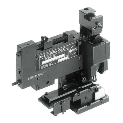
T2 and Terminator Crimp Module
Doc. No: TM-638018500 Release Date: 11-26-12 UNCONTROLLED COPY age 1 of 39
Revision: A Revision Date: 11-26-12
T2™ and Terminator Crimp Module
6380 -8500
Instruction Manual
Description
Operation
Maintenance
2 / 40
2 / 40

Distributor of Molex Connector Corporation: Excellent Integrated System Limited
Datasheet of 0638018500 - T2 & TERMINATOR CRIMP MODULE
T2 and Terminator Crimp Module
Doc. No: TM-638018500 Release Date: 11-26-12 UNCONTROLLED COPY age 2 of 39
Revision: A Revision Date: 11-26-12
Table of Contents
Contents
T2™ and Terminator Crimp Module ......................................................................................................................................................... 1
Safety Warnings and Information.............................................................................................................................................................. 4
Tooling Technical Assistance ................................................................................................................................................................... 5
rincipal Mechanical arts of the Crimp Module ...................................................................................................................................... 6
Section 1 ............................................................................................................................................................................................... 7
General Description ......................................................................................................................................................................... 7
1.1 ....... Description .......................................................................................................................................................................... 7
1.2 ....... Features .............................................................................................................................................................................. 7
1.3 ....... Technical Specification ....................................................................................................................................................... 7
1.4 ....... Delivery Check .................................................................................................................................................................... 7
1.5 ....... Crimp Tooling Accessories (optional) ................................................................................................................................. 7
1.6 ....... Tools ................................................................................................................................................................................... 7
1.7 ....... Application Tooling Specification Sheets ............................................................................................................................ 7
Section 2 ............................................................................................................................................................................................... 9
Set-Up and Operation ...................................................................................................................................................................... 9
2.1 ....... Shut Height ......................................................................................................................................................................... 9
2.2 ....... How to Manually Cycle the ress ..................................................................................................................................... 10
2.3 ....... Crimp Module Installation and Removal ........................................................................................................................... 10
2.4 ....... Tool Set Removal and Installation .................................................................................................................................... 11
2.5 ....... A Quick Checklist rior To The First Crimp ...................................................................................................................... 13
2.6 ....... Conductor Crimp Height Adjustment ................................................................................................................................. 14
2.7 ....... Insulation Crimp Height Adjustment .................................................................................................................................. 14
Section 3 ............................................................................................................................................................................................. 15
Troubleshooting ............................................................................................................................................................................. 15
Section 4 ............................................................................................................................................................................................. 16
Adjustments ................................................................................................................................................................................... 16
4.1. ...... unch and Anvil Alignment ............................................................................................................................................... 16
4.2. ...... Wire Stop Adjustment ....................................................................................................................................................... 16
4.3 ....... Rear Cover Adjustments ................................................................................................................................................... 17
4.4 ....... Track osition Adjustment (T2 tools only) ......................................................................................................................... 18
4.5 ....... Feed Finger Alignment ...................................................................................................................................................... 18
4.7 ....... Terminal Forward Feed Adjustment (Centering the Terminal to the Anvils) ..................................................................... 20
4.8 ....... Back Stroke Feed Adjustments (Terminal pitch or spacing on the strip) ........................................................................... 20
4.9 ....... Crimp Tooling Installation and Removal ........................................................................................................................... 21
Section 5 ............................................................................................................................................................................................. 23
Maintenance .................................................................................................................................................................................. 23
5.1 ....... Cleaning ............................................................................................................................................................................ 23
5.2 ....... Lubrication ........................................................................................................................................................................ 23
5.3 ....... Spare arts ....................................................................................................................................................................... 24
5.4 ....... erishable arts ................................................................................................................................................................ 24
5.5 ....... Crimp Module Storage ...................................................................................................................................................... 25
Section 6 ............................................................................................................................................................................................. 26
6.1 ....... Main arts List .................................................................................................................................................................. 26
6.2 ....... Frame Assembly ............................................................................................................................................................... 28
6.2 ....... Feed Assembly ................................................................................................................................................................. 29
3 / 40
3 / 40

Distributor of Molex Connector Corporation: Excellent Integrated System Limited
Datasheet of 0638018500 - T2 & TERMINATOR CRIMP MODULE
T2 and Terminator Crimp Module
Doc. No: TM-638018500 Release Date: 11-26-12 UNCONTROLLED COPY age 3 of 39
Revision: A Revision Date: 11-26-12
6.2 ....... Ram Assembly .................................................................................................................................................................. 30
6.3 ....... Terminator Set-up ............................................................................................................................................................. 31
Typical T2 Tool Set – Front Carrier (Figure 6-5) ........................................................................................................................... 31
Typical T2 Tool Set – Dual Carrier (Figure 6-6) ............................................................................................................................. 32
Typical T2 Tool Set – Rear Carrier (Figure 6-7) ............................................................................................................................. 33
Typical Terminator Tool Set – Front Carrier (Figure 6-8) ............................................................................................................... 34
Typical Terminator Tool Set – Rear Carrier (Figure 6-9) ............................................................................................................... 35
Typical Terminator Tool Set – Dual Carrier (Figure 6-10) .............................................................................................................. 36
Typical Terminator Tool Set – Center Carrier (Figure 6- 11).......................................................................................................... 37
“T” Micro Terminal (Figure 6-12) .................................................................................................................................................... 38
4 / 40
4 / 40

Distributor of Molex Connector Corporation: Excellent Integrated System Limited
Datasheet of 0638018500 - T2 & TERMINATOR CRIMP MODULE
T2 and Terminator Crimp Module
Doc. No: TM-638018500 Release Date: 11-26-12 UNCONTROLLED COPY age 4 of 39
Revision: A Revision Date: 11-26-12
Safety Warnings and Information
Read and understand all of the instructions and safety information in this
manual before operating or servicing this equipment.
Keep this manual available when using this equipment.
Replacement manuals are available for download at www.molex.com.
SAFETY ALERT SYMBOL
This symbol is used to call your attention to hazards or unsafe practices which could result in an injury
or property damage. The signal word, defined below, indicates the severity of the hazard. The message
after the signal word provides information for preventing or avoiding the hazard.
DANGER
DANGER:
Indicates an imminently hazardous situation which, if not avoided, could result in death or serious injury.
WARNING
WARNING:
Indicates a potentially hazardous situation which, if not avoided, could result in death or serious injury.
CAUTION
CAUTION:
Indicates a potentially hazardous situation which, if not avoided, may result in minor or moderate injury.
CAUTION may also be used to alert against unsafe practices associated with events that could lead
to personal injury.
WARNING
WARNING
Always
we
ar proper eye protection when
Operating or servicing this equipment.
Failure to wear eye protection could result
in serious eye injury from flying debris.
Excessive noise levels.
Always wear proper ear protection when
Operating or servicing this equipment.
WARNING
WARNING
Never wear clothing or jewelery that is loose or
that could potentially enter the equipment
and get caught.
Failure to observe this warning could result in
severe injury or death.
Never
install or service the press
while
connected to any electrical power source.
Disconnect power by unplugging the press
from its power source.
Failure to observe this warning could result
In severe injury or death.
WARNING
WARNING
Never operate, service, install, or adjust this
equipment without proper instruction or without
first reading and understanding the instructions
in this manual and all applicable press manuals.
Always
hand cycle the
module
in the
press
to ensure the tooling is properly aligned.
Failure to observe these precautions may result
In injury or property damage.
5 / 40
5 / 40

Distributor of Molex Connector Corporation: Excellent Integrated System Limited
Datasheet of 0638018500 - T2 & TERMINATOR CRIMP MODULE
T2 and Terminator Crimp Module
Doc. No: TM-638018500 Release Date: 11-26-12 UNCONTROLLED COPY age 5 of 39
Revision: A Revision Date: 11-26-12
WARNING
WARNING
Never
use this
equipment
in a press or wire processing
machine without guards or safety devices that are
intended to prevent hands from remaining in the die space.
This equipment is supplied with no guards and is intended
to be used with the guards the press and/or
the wire processor.
Failure to observe this warning could result in severe
injury or death.
Do not use compressed air to clean
the equipment.
The forces created by compressed
air can force debris into the tool.
Failure to observe these precautions may
result in injury or property damage.
CAUTION
The Molex
Crimp Module is
designed to operate
ONLY in the TM
-
3000 and TM
-
4000 press
with standard shut height
at 135.80mm (5.346”).
Installation in crimp presses with other than standard shut heights can cause severe tool damage. Check the shut height of the
crimp press before operating the Crimp Module. Molex will not be liable for any damages as a result of installation in a crimp
press with nonstandard or improperly set shut height.
Failure to observe these precautions may result in injury or property damage.
CAUTION
Never
perform any service or maintenance other than as described in this manual.
Never modify, alter or misuse the equipment
Molex crimp specifications are valid only when used with Molex terminals, applicators and tooling.
Failure to observe this precaution may result in injury and property damage.
Tooling Technical Assistance
Molex offers tooling technical assistance for customers who may need some guidance for tooling adjustments. This support
can be obtained by calling either of the two numbers listed below and asking for the Molex Tooling Group.
Call Toll Free 1-800-786-6539 (US) 1-630-969-4550 (Global).
This assistance is limited to the operation and set-up of Molex application tools. Questions with regard to Molex connector
products or how to identify the proper tooling and/ or tooling documentation should be directed to your local Molex personnel
or Customer Service Representative.
When calling for service on the applicator it is recommended to have the following: a copy of the Tooling Manual, the specific
Application Tooling Specification and a person familiar with the application tool should be present. The following information
is also recommended to supply:
1. Customer name
2. Customer address
3. erson to contact such as (name, title, e-mail, and telephone number)
4. order number (Lease number also if applicable)
5. Serial number (Lease number also if applicable)
6. Molex Connector product order number
7. Urgency of request
8. Nature of problem
Molex Application Tooling Group
2200 Wellington Court
Lisle, IL 60532, USA
Tel: +1 (630) 969-4550
Fax:+1 (630) 505-0049
Visit our Web site at http://www.molex.com
6 / 40
6 / 40

Distributor of Molex Connector Corporation: Excellent Integrated System Limited
Datasheet of 0638018500 - T2 & TERMINATOR CRIMP MODULE
T2 and Terminator Crimp Module
Doc. No: TM-638018500 Release Date: 11-26-12 UNCONTROLLED COPY age 6 of 39
Revision: A Revision Date: 11-26-12
Figure
-
FEED
LOCKING SCREW
ADJUSTING
SCREW
INSULA
TION
ADJUSTING CAM
RAM
GREASE
FITTING
FRAME
GUIDE
BLOCK
FEED
FINGER
CONDUCTOR
ADJUSTING KNOB
BASE PLATE
PUNCH LOCK
TERMINAL POSITION
ADJUSTING
KNOB
LOCATING PLATE
Principal Mechanical Parts of the Crimp Module
7 / 40
7 / 40

Distributor of Molex Connector Corporation: Excellent Integrated System Limited
Datasheet of 0638018500 - T2 & TERMINATOR CRIMP MODULE
T2 and Terminator Crimp Module
Doc. No: TM-638018500 Release Date: 11-26-12 UNCONTROLLED COPY age 7 of 39
Revision: A Revision Date: 11-26-12
Section
General Description
. Description
The Molex T2™and Terminator Crimp Module provides an
effective method of transitioning T2 or Terminator tooling
from the TM-40 or TM-42 press or Base Unit into the TM-
3000 or TM-4000 press
This Crimp Module is installed ONLY in the Molex TM-3000
and TM-4000 Universal resses. This unit will not work in
other industry-standard presses. The Crimp Module
features minimal setup time without the need for shimming,
is versatile, reliable, easy to install, and is designed for mid-
volume to high-volume, semi or fully automatic operations.
Molex offers the following presses for operating the Crimp
Module:
TM-3000 ress 120 V 60 Hz. 6380 -7200
TM-3000 ress 240 V 50 Hz. 6380 -7300
TM-4000 ress 240 V 60 Hz. 6380 -7600
.2 Features
Fine adjustment allows users to achieve crimp height
target by adjusting a wedge (0.74 mm total adjustment)
for conductor crimp height and an 8-step cam (0.23mm
per step) for insulation crimp height.
Independent adjustment cams allow users to quickly
adjust the conductor or insulation crimp height
independently.
Quick crimp punch removal.
Compatible ONLY with the Molex TM-3000 and TM-
4000 Universal resses
Automatic terminal feed (on ram upstroke only).
Quiet operation; low maintenance and easy to keep
clean.
Accepts any Molex T2 or Terminator tooling.
.3 Technical Specification
Dimensions
(Crimp Module Only)
Width: 190mm (7.5")
Depth: 121mm (4.8")
Height: 146mm (5.7")
Weight (Crimp Module Only)
4.1kg (9lbs)
Guarding
The Crimp Module is supplied with no guards and is
intended to be used with the guards installed on the
TM-3000 or TM-4000 press.
Do not operate the Crimp Module
without press guards installed.
.4 Delivery Check
Carefully remove the Crimp Module from its shipping
container; note that the following items are also
included in the package:
TM-638018500 Operation Manual 1
Crimp Module with serial tag 1
.5 Crimp Tooling Accessories (optional)
Molex Order No. 63801-7240 Terminal Oiler
(Appendix C)
Molex Order No. 63800-2820 Digital Crimp Micrometer
Molex Order No. 63817-0000 Hand Held Wire strippers
Molex Order No. 63801-9200 neumatic Bench Top
Wire Strip Machine
Molex Order No. 63801-9250 Metric Bench Top Wire
Strip Machine
Molex Order No. 63801-9100 ull Force Tester Bench
Top
Molex Order No. 63801-9700 ull Force Tester Hand
Held
Molex Order No. 63800-2810 Eye loupe
.6 Tools
The following tools are recommended for setup and
adjustments to the applicator:
1. Metric and English hex wrench sets
2. Adjustable wrench
3. Wire stripper / cutter
4. Feeler gages/ shim stock
5. Eye loupe (5X)
.7 Application Tooling Specification Sheets
Molex ships specification sheets with all T2 or
Terminator tooling. The specification sheet contains
the following:
8 / 40
8 / 40

Distributor of Molex Connector Corporation: Excellent Integrated System Limited
Datasheet of 0638018500 - T2 & TERMINATOR CRIMP MODULE
T2 and Terminator Crimp Module
Doc. No: TM-638018500 Release Date: 11-26-12 UNCONTROLLED COPY age 8 of 39
Revision: A Revision Date: 11-26-12
Ε
ΕΕ
Ε Terminal numbers
Ε
ΕΕ
Ε Wire AWG ranges
Ε
ΕΕ
Ε Insulation diameter ranges
Ε
ΕΕ
Ε Strip lengths
Ε
ΕΕ
Ε ull force
Ε
ΕΕ
Ε Crimp heights
Ε
ΕΕ
Ε Bell mouth
Ε
ΕΕ
Ε Bend, twist, and roll limits
Ε
ΕΕ
Ε Tooling parts list and assembly
The specification sheets contain all the critical information on tooling replacement part numbers and inspection
characteristics. Copies should be kept on hand and made available.
Application Tooling Specification and other Molex tooling documentation is available for download on the Molex website
(www.molex.com).
To find Application Tooling Specification sheets, go to Molex.com. Using the “Search Box” on the main page, enter the
desired tooling order number. When the tooling page comes up, go to the “Specifications & Other Documents” section and
click on the “Application Tooling Specification“ link.
9 / 40
9 / 40

Distributor of Molex Connector Corporation: Excellent Integrated System Limited
Datasheet of 0638018500 - T2 & TERMINATOR CRIMP MODULE
T2 and Terminator Crimp Module
Doc. No: TM-638018500 Release Date: 11-26-12 UNCONTROLLED COPY age 9 of 39
Revision: A Revision Date: 11-26-12
Figure 2
-
PRESS
PRESS QUICK CHANGE
MOUNTING PLATE
SHUT HEIGHT
GAUGE
Section 2
Set-Up and Operation
Read the following instructions before attempting to operate the Crimp Module.
2. Shut Height
The shut height for the Crimp Module is 135.80mm (5.346"). The shut height for the crimp press is calibrated using a Shut Height
Gauge. See Figure 2-1. The gauge is designed to apply the proper load at 135.80mm (5.346") shut height. Molex offers an
industry standard shut height gauge (order number 63800-7900) that will fit in the TM-3000 and TM-4000 crimp presses. It is
recommended that the crimp press shut height be checked regularly.
The Crimp Module is designed to operate in the TM-3000 and TM-4000 crimp presses with standard shut height of 135.80mm
(5.346"). Installation in crimp presses with non-standard shut heights or ram strokes greater than 30mm can cause severe tool
damage. It is recommended before installation, a check of the shut height be performed. The correct shut height is required to
prevent the punches from hitting the anvils and the cut-off tooling from crashing. Calibrated presses also allow various T2 and
Terminator tools to be installed with minimal adjustment to the Crimp Module.
Measuring Press Shut Height
Always turn off and disconnect the power supply to the press.
1. Open the guard door.
2. Remove the applicator or Crimp Module from the press. See Section 2.3 Module Installation and Removal for additional
information. Clean the bottom of the press ram and top of the quick change mounting plate.
3. lace the shut height gauge onto the press quick change mounting plate. Align the gauge to the ram as shown in
Figure 2-1.
4. Manually cycle the press to the down stroke position. See Section 2.2, ow to Manually Cycle the Press, or follow the
TM-3000 Operation Manual (order number TM638017299) Section 3.3 Manually Cycling the Press.
5. Read the shut height measurement from the front of the gauge. Follow the gauge manufacturers’ instruction; usually the
gauge reads “0” when shut height is 135.80mm (5.346").
6. If adjustments are necessary, refer to the TM-3000 press manual for adjustment of the press shut height.
7. Repeat the above steps until the correct shut height is obtained.
8. Shut height gauges must be calibrated on a regular basis.
10 / 40
10 / 40

Distributor of Molex Connector Corporation: Excellent Integrated System Limited
Datasheet of 0638018500 - T2 & TERMINATOR CRIMP MODULE
T2 and Terminator Crimp Module
Doc. No: TM-638018500 Release Date: 11-26-12 UNCONTROLLED COPY age 10 of 39
Revision: A Revision Date: 11-26-12
Figure 2-2
FOOT SWITCH
CORD
MOTOR
TURN
CLOCKWISE
T
-
HANDLE
WRENCH
POWER CORD
2.2 How to Manually Cycle the Press
Always turn off and disconnect the power supply to the press.
Always hand cycle the Crimp Module in the press to ensure the tooling is properly aligned.
Note: When the press guard is open make sure the power is disconnected from the motor (MOTOR ON light is not
illuminated)
Hand cycling the press is necessary to confirm correct tool
alignment and terminal feed adjustment. It also allows setup
personnel to observe the crimping cycle in slow-motion.
Manually Cycling the TM3000 and TM4000 Presses
1. Insert the hand-cycle T wrench (furnished with the
press) through the access hole in the center of the
motor’s rear cover and locate it on the motor shaft.
See Figure 2-2.
2. Rotate the wrench clockwise. This turns the motor
and moves the ram down and up.
3. Always return the press ram back to top dead center to
ensure that the ram is in the startup position.
4. Remove the T-handle wrench.
NOTE: When the T-handle wrench is inserted onto
the motor shaft the power is automatically disconnected from the motor. ress the green MOTOR ON button to
restore power to the motor.
2.3 Crimp Module Installation and Removal
Always turn off and disconnect the power to the press.
Installation
1 Open the press guard door.
2 Clean the quick change mounting plate of scrap or chips that may interfere with the Crimp Module installation.
Molex recommends a soft brush; do not use compressed air to clean the equipment. The forces created by
compressed air can force debris into the tool.
3 To install the Crimp Module, follow the procedure below:
a. Using a 4mm hex wrench, turn the M5 socket head cap screw clockwise until the locking clamp is fully opened.
b. Slide the Module’s lug bolt into the press ram yoke.
c. ull the Crimp Module’s frame down until the Module’s base plate rests on the quick change mounting plate.
d. Visually align the Crimp Module’s base plate notches on the left with the location clamps on the press quick-change
mounting plate.
e. Slide the Crimp Module to the left until the two notches in the base plate engage against the location clamps. See
Figure 2.3.
f. To lock applicator, turn the M5 socket head cap screw counterclockwise until tight.
11 / 40
11 / 40

Distributor of Molex Connector Corporation: Excellent Integrated System Limited
Datasheet of 0638018500 - T2 & TERMINATOR CRIMP MODULE
T2 and Terminator Crimp Module
Doc. No: TM-638018500 Release Date: 11-26-12 UNCONTROLLED COPY age 11 of 39
Revision: A Revision Date: 11-26-12
PRESS
RAM Y
OKE
CRIMP MODULE
BASE PLATE
M5 SHCS
LOCKING
CLAMP
QUICK CHANGE
MOUNTING PLATE
LOCATION
CLAMPS
Figure 2-3
LUG BOLT
4 Close the press guard door.
5 Hand cycle the press. See Section 2.2 ow to Manually Cycling the Press.
6 Reconnect power and press the green MOTOR ON button.
Removal
Remove the Crimp Module by reversing the previous steps. When storing the Module, always leave a strip of terminals in the
Module’s track to prevent damage to the tooling. See Section 5.5 Storage.
2.4 Tool Set Removal and Installation
Power must be disconnected from the press. Manual press cycling (hand cycling) is absolutely required
for safety and preventing equipment damage. Always hand cycle when trouble shooting or changing
adjustments, tooling, terminal reel, crimp module, or accessories.
Tool Set Removal
1. Disconnect power and open the guard door.
2. Set both the conductor and insulation cams to their highest (loosest) setting.
For the conductor cam, loosen the COND LOCK set screw on the ram face plate. Turn the conductor adjusting knob
counterclockwise until it stops.
For the insulation cam, slide it all the way to the left.
3. Remove the M6 button head cap screw and remove the right locating plate.
4. Lift the feed finger clear and slide the terminator die out of the Crimp Module.
5. Remove the punches, nose hold-down, rear striker, and center carrier cutoff tooling from the ram.
6. The terminator tooling is best stored in its original container.
Tool Set Installation
Make sure the proper crimp tooling is used for the terminal. Find the terminal part number on the terminal reel label
and compare it to the Application Tooling Specification sheet for the tooling. All Molex crimp tooling has an
Application Tooling Specification sheet.
Before any die is installed make sure the cover alignment procedure and the track adjustment procedure, (when applicable)
have been completed. See the specific terminator die instruction manual for these procedures.
12 / 40
12 / 40

Distributor of Molex Connector Corporation: Excellent Integrated System Limited
Datasheet of 0638018500 - T2 & TERMINATOR CRIMP MODULE
T2 and Terminator Crimp Module
Doc. No: TM-638018500 Release Date: 11-26-12 UNCONTROLLED COPY age 12 of 39
Revision: A Revision Date: 11-26-12
DRAG
CAM
DRAG FRAME
ST
TERMINAL CENTERED
ABOVE ANVILS
TERMINAL STRIP
LIFT THE FEED
FINGER UP
ROTATE
Figure 2
-
4
“T2” Style
1. ower down the press and open the guard door.
2. Some crimp tools may have nose hold down, rear strikers, or center carrier cutoff tooling. If these items are used,
attachment points are located behind the punches either in the front or on the bottom of the Crimp Module’s ram. Refer to
the Specification sheet supplied with each individual terminator die for parts supplied with that terminator.
3. Fit the (2) punches in the opening on the underside of the ram. The conductor punch is positioned in the rear. See
Figure 6-5. A click will be heard when the punch retaining/release pin engages the slots in the punches
4. Set both the conductor and insulation cams to their highest (loosest) setting.
5. The front plunger striker mounts in front of the insulation crimp punch and is attached with a #10-32 set screw and hex nut
through the hole in the ram’s face plate. The set screw is adjusted to minimize punch float.
6. Clean the Crimp Module’s base plate of debris or chips that may interfere with the tool set installation.
7. Remove the right locating plate from the bolster plate by removing the M6 button head cap screw.
8. Lift the feed finger clear and slide the terminator track notch onto the left locating plate.
9. Attach the right locating plate against the anvils and tighten the M6 button head cap screw.
Always hand cycle the Crimp Module after installing tooling to ensure proper tool alignment.
Loading and Unloading the Terminal Strip
1. The specified terminals are printed on the specification sheet for the Terminator. Only use the Molex terminals on the
specification sheet which is supplied with the Terminator.
Always turn off and disconnect the power supply to the press when loading or unloading terminals
2. Install the terminal reel on the press reel arm and unwind about 400mm (15 in.) of terminals off the reel.
CAUTION: Terminals and terminal carrier strips may have sharp edges. Use caution while handling terminals.
“T2” STYLE TOOLING
1. If using a T2 Terminator, rotate the drag cam until the drag frame is in the upright position. This will allow the terminal to slide
easily through the terminal track. See Figure 2-4.
2. ush the terminal strip through the track until the first terminal comes to rest centered above the crimp anvils.
3. If severe resistance is encountered or the terminal strip does not fit, a rear cover adjustment may be needed. See Section 4.3
4. Rotate the drag cam to engage the terminal drag frame.
5. Cycle the press by hand so that the feed finger transfers the next terminal to a centered position over the crimp
anvils. Check that all other parts slide and engage without any interference. The press should be hand cycled several
times.
6. When unloading the terminal strip, make sure the power is turned off and disconnected from the press.
13 / 40
13 / 40

Distributor of Molex Connector Corporation: Excellent Integrated System Limited
Datasheet of 0638018500 - T2 & TERMINATOR CRIMP MODULE
T2 and Terminator Crimp Module
Doc. No: TM-638018500 Release Date: 11-26-12 UNCONTROLLED COPY age 13 of 39
Revision: A Revision Date: 11-26-12
DRA
G FINGER
ST
TERMINAL
CENTERED ABOVE ANVILS
TERMINAL
STRIP
LIFT THE FEED
FINGER UP
Figure 2
-
5
“T” Style
ANTI
-
BACK
UP FINGER
DRAG AND ANTI
-
BACK
UP PINS
7. Rotate the drag cam until the drag frame is in the upright position.
8. Raise feed finger and pull terminal strip backwards until disengaged from applicator track. See Figure 2-4. If
preferred, cut the terminal carrier strip and pull it forward through the applicator track with needle nose pliers.
9. Close the guard door and restore power to the press.
“T” (TERMINATOR) STYLE TOOLING
1. If using a “T” style Terminator, push both the drag and anti-backup pins located on the front of the terminator die. This will allow
the terminals to slide freely through the terminal track. See Figure 2-5.
2. ush the terminal strip through the track until the first terminal is centered above the crimp anvils. If severe resistance is
encountered or the terminal strip does not fit, a rear cover adjustment may be needed. See Section 4.3.
3. Release the terminal drag and anti-backup pins to engage the terminal drag frame on the track.
4. Hand-cycle the press so the feed finger transfers the next terminal to a centered position over the crimp anvils.
5. Check that all other parts slide and engage without any interference. The press should be hand cycled several times.
6. When unloading the terminal strip, make sure the power is turned off and disconnected from the press.
7. Raise terminal drag finger and anti-backup finger from the carrier strip.
8. Lift the feed finger and pull terminal strip backwards until disengaged from terminator track. If preferred, cut the terminal carrier
strip and pull it forward through the terminator track with needle nose pliers.
9. Close the guard door and restore power to the press.
2.5 A Quick Checklist Prior To The First Crimp
The T2 and Terminator tooling is modular and can be installed and immediately operated, however preventive measures should
be practiced to assure safe operation and prevent accidental tooling damage.
In many cases, T2 and terminator tooling can crimp various Molex terminals. The terminal tested and shipped with
the tooling may not be the actual terminal (or the actual wire) the customer is using. This may require some minor
adjustments BEFORE crimping under press power.
1. The Crimp Module must be hand-cycled to verify there is no mechanical interference.
2. Verify mechanical function
Terminal cutoff, single terminal feed, and crimped terminal is ejected.
3. Never operate the Crimp Module if there is a feed problem. Correct this first and proceed with setup.
Verify the Crimp Module feeds terminals perfectly to the anvil center.
Fine tuning of the terminal feed may be required depending on the application.
4. Inspect the crimps according to the Application Tooling Specification sheet.
5. Adjust conductor and insulation crimp heights accordingly. See Section 2.6 and 2.7.
14 / 40
14 / 40

Distributor of Molex Connector Corporation: Excellent Integrated System Limited
Datasheet of 0638018500 - T2 & TERMINATOR CRIMP MODULE
T2 and Terminator Crimp Module
Doc. No: TM-638018500 Release Date: 11-26-12 UNCONTROLLED COPY age 14 of 39
Revision: A Revision Date: 11-26-12
CONDUCTOR
ADJUSTING KNOB
INSULATION
ADJUSTING CAM
CONDUCTOR
LOCK SCREW
Figure 2
-
6
2.6 Conductor Crimp Height Adjustment
1. With the guard door closed, place a stripped length of suitable wire into the terminal and crimp the wire under power.
Strip length for the wire can be found in the Application Tooling Specification shipped with the tooling, or downloaded
from the Molex website.
2. Inspect the quality of conductor crimp and measure the crimp height. A crimp micrometer should be used (order no.
63800-2820); refer to the Crimp Quality Manual (document no. TM-638000029), Section 7. If adjustments are
necessary, disconnect the power from the press. Open the guard door. The desired crimp height can be achieved by
loosening the COND LOCK screw and turning the turning conductor cam adjusting knob clockwise to lower the crimp
height or counterclockwise to raise the crimp height. Tighten the COND LOCK screw to prevent the conductor crimp
adjustment from moving. See figure 2-6. The conductor adjusting knob should be adjusted in one-turn increments.
3. Close the guard door and repeat steps 1 – 3 until the desired crimp height is obtained. See the Crimp Quality Manual
(document no. TM-638000029), Section 7 for more information.
4. erform a pull test on conductor crimp to verify the mechanical integrity of the crimp. Refer to the Molex ull Force Tester
(order nos. 63801-9100 and 63801-9700) Application Tooling Specification Sheets or the Crimp Quality Manual for basic
pull force instructions.
2.7 Insulation Crimp Height Adjustment
1. lace a stripped length of the appropriate wire into the terminal and crimp under power.
2. Observe the quality of the insulation crimp and measure the crimp height. See the Crimp Quality Manual for more
information.
3. If adjustments are necessary, always turn off and disconnect the power supply from the press. Open the guard door.
4. Slide the insulation-adjusting cam and observe the number in the window below INS SET to achieve the desired insulation
height.
Each increment represents approximately 0.23mm (.009") for a total adjustment of .60mm (0.063"). The " " setting
is for the loosest (tallest) crimp height and the "8" setting the tightest (smallest) crimp height. It is recommended that
the customer start with the loosest setting which is “1”, and make test crimps until the proper insulation crimp height is
achieved.
5. Repeat the steps 1 – 3 until the desired insulation crimp height is obtained.
Note: Due to the large variety of insulation wall thickness, materials, and hardness, insulation crimp height is not typically
specified. For each different wire type, the insulation crimp height can be measured, recorded, and inspected as a quality
indicator.
Different applicator options are available, listed on molex.com, to better achieve optimal crimps for various wire
insulation types
15 / 40
15 / 40

Distributor of Molex Connector Corporation: Excellent Integrated System Limited
Datasheet of 0638018500 - T2 & TERMINATOR CRIMP MODULE
T2 and Terminator Crimp Module
Doc. No: TM-638018500 Release Date: 11-26-12 UNCONTROLLED COPY age 15 of 39
Revision: A Revision Date: 11-26-12
Section 3
Troubleshooting
Symptom
Cause
S
ection
Solution
Terminals
not feeding
Terminal strip bent or damaged
Replace terminals
.
Feed finger worn or not properly adjusted
4.5
Check proper finger setting
Drag plate not holding terminal strip
Check compression springs
and
close the drag.
Feed finger not moving back enough to pick
up the terminal (pitch) 4.8 Set terminal feed backstroke.
Terminal jammed under cover plate
Clear and re
load
terminal
strip
Excessive
Bell mouth
Conductor punch worn
4.9
Replace
p
unch
.
Track out of position 4.4
Adjust base and track for proper
alignment with the punches and anvil.
Cut-off plunger
does
not return to
original position
Cut
-
off
plunger
retainer
screws
over
-
tightened
Reduce tigh
tening torque on screws
Cut
-
off plunger spring damaged or broken
Replace spring
per specification sheet
.
Cut edges worn or damaged
lunger, retainer, and insulation anvil 4.9
Remove scoring marks. If problem not
solved, replace with new tooling.
Conductor crimp
is too loose
Wrong tooling
4.9
Replace
per specification sheet
.
Tooling worn or damaged
4.9
Replace per specification sheet
.
Wrong cam setting
2.
6
Measure crimp height and adjust accordingly
.
ress shut height too high
2.1
Adjust
press
shut height
to 135.8mm
Conductor crimp
Is too tight
Wrong tooling
4.9
Replace per specification sheet
.
Cam out of adjustment
2.6
Measure crimp height and adjust accordingly
.
ress shut height is too low
2.1
Adjust
press shut height
to 135.8mm
Insulation crimp
Is too tight
Cam out of adjustment
2.7
Readjust insulation cam
.
Wrong tooling
4.9
Replace per specification sheet
.
ress shut height is too low
2.1
Adjust
press shut height
to 135.8mm
Terminal sticks
during crimping
Wrong tooling
4.9
Replace
per specification sheet
.
Tooling worn or damaged
4.9
Replace per specification sheet
.
C
rimp height to
o
low
2.
6
Measure crimp height and adjust accordingly
.
Gold plating and/or some high tensile materials
Appendix
Install a terminal oiler.
Terminals bent
up or down
See
causes for
“terminals sticking”
T
rack
set too far in or too far out
4.4
Adjust track.
Nose hold down misadjusted or missing.
Refer to specification sheet
(if applicable)
Crimp extrusion)
See
causes for
“conductor crimp too tigh
t”
2.
6
Gold plating and/or some high tensile materials
Appendix
Install a terminal oiler.
Wrong tooling
4.9
Replace per specification sheet
.
Tooling worn or damaged
4.9
Replace per specification sheet
.
Wire brush
inconsistent
Wire stop out of adju
stment
4.2
Adjust accordingly
.
Wire stop missing
1.7
Replace per specification sheet
.
Operator applying too much force against
wire stop
Adjust method of presenting wire into
the machine.
Insulation crimps
do not
provide strain relief
(I C- A620)
Verify wire insulation diameter is within
the range of the terminal (specification sheet) 2.7 Adjust accordingly or see if alternate tooling
Is available at molex.com.
16 / 40
16 / 40

Distributor of Molex Connector Corporation: Excellent Integrated System Limited
Datasheet of 0638018500 - T2 & TERMINATOR CRIMP MODULE
T2 and Terminator Crimp Module
Doc. No: TM-638018500 Release Date: 11-26-12 UNCONTROLLED COPY age 16 of 39
Revision: A Revision Date: 11-26-12
Section 4
Adjustments
There are many adjustments on the Crimp Module. Be aware of what adjustments are made to the Module, as making one
adjustment can sometimes influence another. For example, moving the track for a bell mouth adjustment may require the feed
finger to be realigned. It is best practice to have frequent five minute preventive maintenance checks and cleanings before and
after each use. Regular cleaning, lubrication, spot checks for tooling wear, and alignment can prevent production problems and
allow time for replacement parts to be delivered if needed.
4. . Punch and Anvil Alignment
Note: Always clean mounting surfaces of crimp tooling and tooling holders prior to alignment.
Do not use compressed air to clean the equipment.
The forces created by compressed air can force debris into the tool.
Failure to observe these precautions may result in injury or property damage.
1. Disconnect the power supply from the press. Open the guard door.
2. With a terminal centered over the anvils, slightly release anvil mounting screw. See Figures 4-1 and 4-2.
3. lace the hand cycling wrench through the access hole in the press motor’s rear cover.
4. Slowly lower the press ram until it is in the fully down position. With the terminal resting on the anvils the punch will align the
bottom tooling.
5. While the ram is fully down, tighten the anvil mounting screws to ensure exact alignment of punches and anvils. Tighten
center carrier cut-off tooling if applicable.
6. Use the hand cycle wrench to bring the ram back to top dead center.
7. Close the guard door and restore power to the press.
4.2. Wire Stop Adjustment
The wire stop is used to control the amount of conductor brush beyond the conductor crimp grip.
For automatic wire processing machines, the wire stop can be moved back and used to assist in the stripping of the terminal from
the crimp punches. However, in certain circumstances the wire stop may need to be completely removed when running on an
automated machine.
1. Check the Application Tooling Specification sheet to obtain the correct wire strip length.
2. lace the correct wire gauge that is properly stripped into the terminal and crimp the wire under power. rior to crimping
under power make sure the tooling has been hand-cycled. See Section 2-1 ow to Manually Cycle the Press.
3. Observe quality of crimp and the wire insulation and brush position.
M4 SHCS (2)
Figure 4
-
“T2” STYLE
PLUNGER
RETAINER
Figure 4
-
2
“T” STYLE
# 0
-
32 SHCS
PLUNGER
RETAINER
17 / 40
17 / 40

Distributor of Molex Connector Corporation: Excellent Integrated System Limited
Datasheet of 0638018500 - T2 & TERMINATOR CRIMP MODULE
T2 and Terminator Crimp Module
Doc. No: TM-638018500 Release Date: 11-26-12 UNCONTROLLED COPY age 17 of 39
Revision: A Revision Date: 11-26-12
Figure 4
-
4
TERMINAL
M4 X 2mm BHCS (2)
REAR COVER
DRAG RELEASE
UP POSITION
TRACK
POINT
REAR COVER FRONT EDGE
POINT 2
PUSH REAR COVER
Figure 4
-
3
WIRE STOP
WIRE STOP
MOUNTING SCREW
WIRE
M5 SHCS
FOR WIRE STOP
WIRE STOP
WIRE
4. If adjustments are necessary, turn off the press. Open the guard door.
5. Hand cycle the press to lower the ram.
6. On the T2 tooling, use a 4mm hex wrench to loosen the M5 socket head cap screw located on the side of the anvil mount.
See Figure 4-3.
7. For some T2s andTerminator (“T” style) tooling, the wire stop mounting screw may be located on top of the anvil mount.
8. Adjust the position of the wire stop by moving the wire stop towards the operator to decrease the brush length and towards
the press to increase it.
9. Feeler gauge or shim stock can be used to create a gap between the back of the conductor punch and front of the wire stop.
The amount of shim used here is directly related to the amount of wire brush.
10. Tighten the M5 socket head cap screw.
11. Hand cycle the press to ensure the conductor punch does not hit the wire stop. Then crimp a terminal under power and
observe the quality of the termination.
4.3 Rear Cover Adjustments
Always turn off and disconnect the power supply to the press before making adjustments.
1. Disconnect the power from the press. Open the guard door.
2. Remove the terminator from the Crimp Module. See Section 2.3, Crimp Module Installation and Removal
3. For the T2 style tooling, rotate the drag cam until the drag frame is in the upright position.
4. With an 8-10” long strip of terminals installed in the track, push the rear cover towards the front of the track to eliminate any
excessive play between points 1 and 2. See Figure 4-4.
5. Slide the strip of terminals forward and back while lightly pushing the rear cover towards the front of the track. The goal is to
have minimal movement between points 1 and 2, but still allow the strip of terminals to slide freely.
18 / 40
18 / 40

Distributor of Molex Connector Corporation: Excellent Integrated System Limited
Datasheet of 0638018500 - T2 & TERMINATOR CRIMP MODULE
T2 and Terminator Crimp Module
Doc. No: TM-638018500 Release Date: 11-26-12 UNCONTROLLED COPY age 18 of 39
Revision: A Revision Date: 11-26-12
6. After the correct position is achieved, tighten the two M4 button head cap screw (T2) or #8 button head cap screw (“T” style) and
remove the strip of terminals.
7. Re-install the terminator in the Crimp Module. See Section 2.3, Crimp Module Installation and Removal
4.4 Track Position Adjustment (T2 tools only)
Disconnect the power supply to the press.
1. Open the guard door.
2. Depending on the amount of movement, the feed finger mount may need to be loosened and readjusted. See Section 4.5
Feed Finger Alignment.
3. Determine which way the track needs to move. To decrease front cut-off tab or to increase bell mouth, the track should be
adjusted toward the operator. The track is usually adjusted toward the press to decrease bell mouth or to help straighten a
bend-up condition.
4. Remove the Crimp Module from the press. See Section 2.3.
5. To position the terminal track in or out, use a 4mm hex wrench to loosen the M5 lock screw located on the underside of the
track. This screw can be accessed through a slot in the Crimp Module’s base plate. See Figure 4-5.
6. Slide the track in or out to the desired position.
7. To lock the track in position, tighten the M5 lock screw.
8. Slide a length of terminal strip through the track and make sure it feeds freely into the cutoff plunger(s).
9. If the feed finger mount was loosened during the track positioning, remember to tighten its mounting screw.
10. The wire stop may need to be re-adjusted for insulation and brush position.
See Section 4.2 Wire Stop Adjustment.
11. Hand cycle the press to ensure the terminal is positioned properly on the anvils and does not have an excessive cutoff tab.
See Section 4.6 Terminal Position Adjustment. Also, verify the terminal feed operation.
12. Close the guard door and remove the hand-cycle wrench from the motor.
13. Restore power to the press, crimp a terminal under power, and observe the quality of the termination.
14. Repeat the above steps until the desired terminal position is obtained.
4.5 Feed Finger Alignment
Never operate the Crimp Module if there is a feed problem. Tooling damage can result. Adjust the
insulation and conductor adjusting cams to create a loose crimp while solving feed problems. (Move the
insulation cam to to the #1 position and turn the conductor adjusting screw CCW until the conductor cam stops.)
ACCESS SLOT FOR
TRACK ADJUSTMENT
Figure 4
-
5
BASE PLATE
19 / 40
19 / 40

Distributor of Molex Connector Corporation: Excellent Integrated System Limited
Datasheet of 0638018500 - T2 & TERMINATOR CRIMP MODULE
T2 and Terminator Crimp Module
Doc. No: TM-638018500 Release Date: 11-26-12 UNCONTROLLED COPY age 19 of 39
Revision: A Revision Date: 11-26-12
CENTER OF CARRIER
STRIP PILOT HOLE
FEED
FINGER
Figure 4-6
FEED GUIDE
1. Typically, terminals are fed by the carrier strip pilot hole. In this case, position the feed finger to align to the center of the
carrier strip pilot hole. See Figure 4-6.
2. Disconnect power from the press. Open the guard door.
3. Using a 2.5mm hex wrench, loosen the M3 socket head cap screw located on the slotted hole of the feed finger mount.
While raising the feed finger slightly, slide the feed finger to the desired position. See Figure 4-7.
4. If the feed finger mount cannot be moved far enough, remove the M3 socket head cap screw completely and install it in the
next tapped hole in the feed lever.
5. Tighten the M3 socket head cap screw to lock the feed finger in position.
6. Hand cycle the press to verify proper feed operation.
7. Close the guard door, remove the hand-cycle wrench from the motor, and restore press power.
4.6 Feed Finger Spring Tension
The feed finger is held against the terminal strip by force created from a torsion spring. If the force is too low, the feed finger
may “skip” over the terminal strip and result in no feeding or partial feeding.
1. Disconnect power from the press. Open the
guard door.
2. Use a small regular screwdriver in the slot of
the feed finger pivot shaft to keep the torsion
spring from unwinding. See Figure 4-8.
3. Using a 2.5mm hex wrench, loosen the M3
socket head cap screw holding the pivot
shaft.
4. Turn the screwdriver clockwise to increase
the tension of the torsion spring or
counterclockwise to decrease it. Turn in small
increments (30°) to avoid damaging the
spring.
5. While holding the pivot shaft from turning,
tighten the M3 socket head cap screw.
6. Since the pivot shaft can move axially when
loosened, check the feed finger alignment
and adjust if necessary.
7. Hand cycle the press to verify proper feed operation.
8. Close the guard door, remove the hand-cycle wrench from the motor, and restore press power.
M3 SHCS
FEED
FINGER MOUNT
FEED FINGER
PIVOT SHAFT
TORSION
SPRING
SLOT IN PIVOT SHAFT
Figure 4
-
8
M3 SHCS
FEED
FINGER
MOUNT
FEED FINGER
Figu
re 4
-
7
20 / 40
20 / 40
Table of contents
Other molex Crimping Tools manuals

molex
molex 207129 Series User manual

molex
molex 207129 Series User manual

molex
molex 63811-5800 User manual

molex
molex 207129 Series User manual

molex
molex 63825-6900 User guide

molex
molex 63827-1300 User manual

molex
molex 63825-9700 User manual

molex
molex PremiumGrade 63827-1700 User manual

molex
molex 207129 Series User manual

molex
molex 63811-7070 User manual

molex
molex 63819-3700 User manual

molex
molex CR60930B User manual

molex
molex 63827-1600 User manual

molex
molex 213309-1400 User manual

molex
molex AT 2100 User manual

molex
molex 63823-5570 User manual

molex
molex 64001-7300 User manual

molex
molex 207129 Series User manual

molex
molex 63825-9570 User manual

molex
molex 63811-7100 User manual