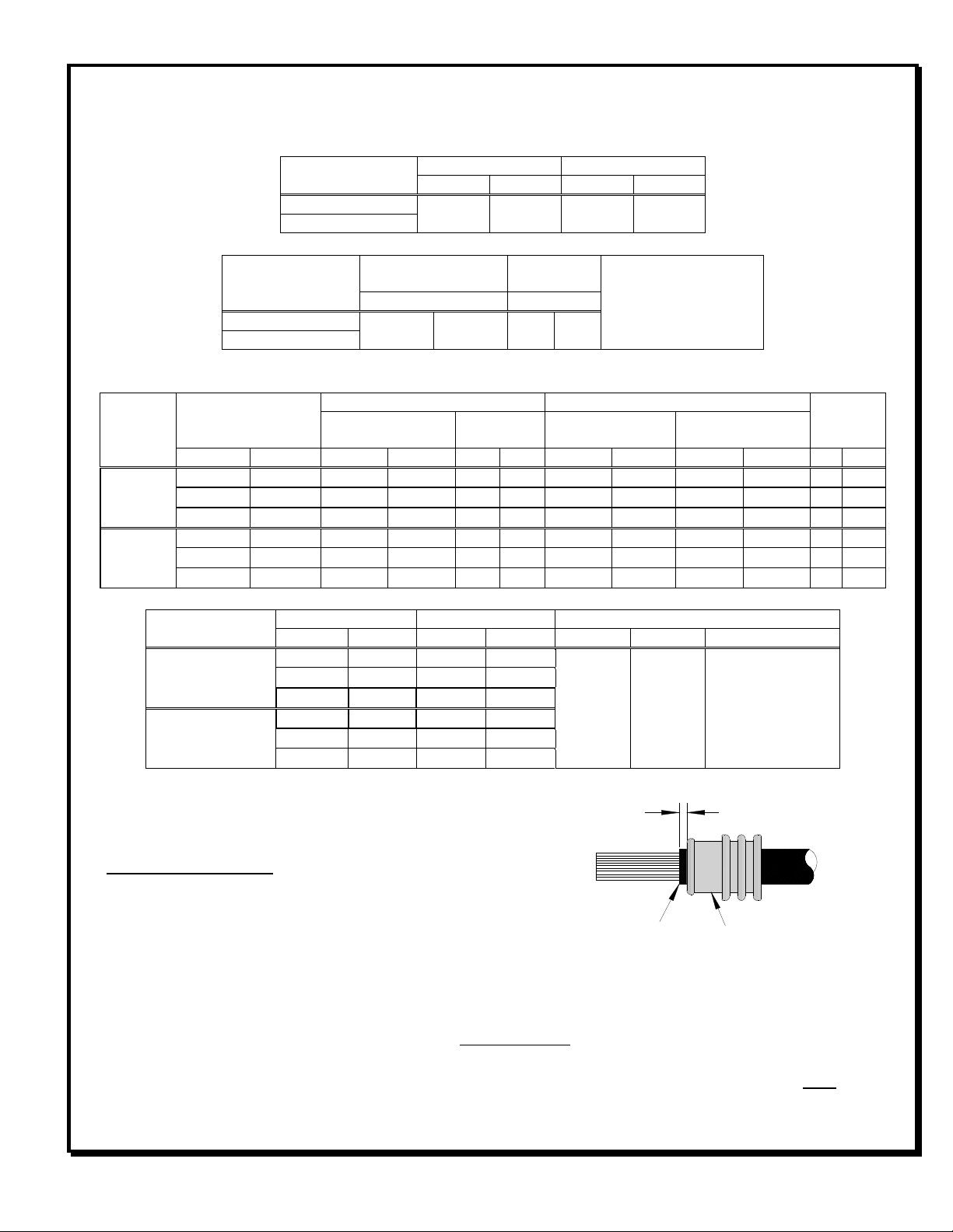
Hand Crimp Tool For CTX150 SWS Receptacle Terminals
Doc No: ATS-6 82 4500 Release Date: 08-26-1 UNCONTROLLED COPY Page 5 of 7
Revision: A Revision Date: 08-26-1
UP MARKS
FRONT
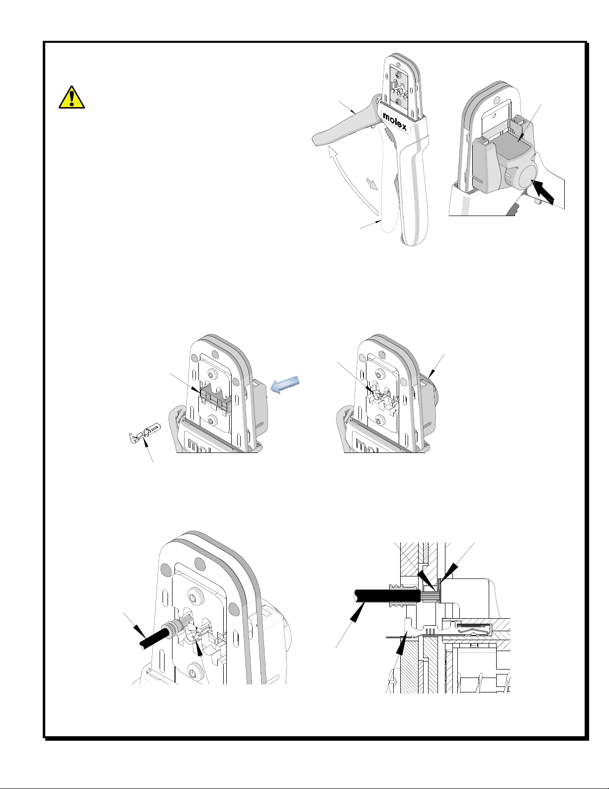
6. Holding onto the lower part of the locator with your thumb and index finger, insert the locators top hooks (2)
into the hand tool top slots.
7. Rotate the locator down and press the lower tabs into the two bottom slots of the hand tool. To secure the
locator into place, the lower tabs must snap into place on the hand tool frame.
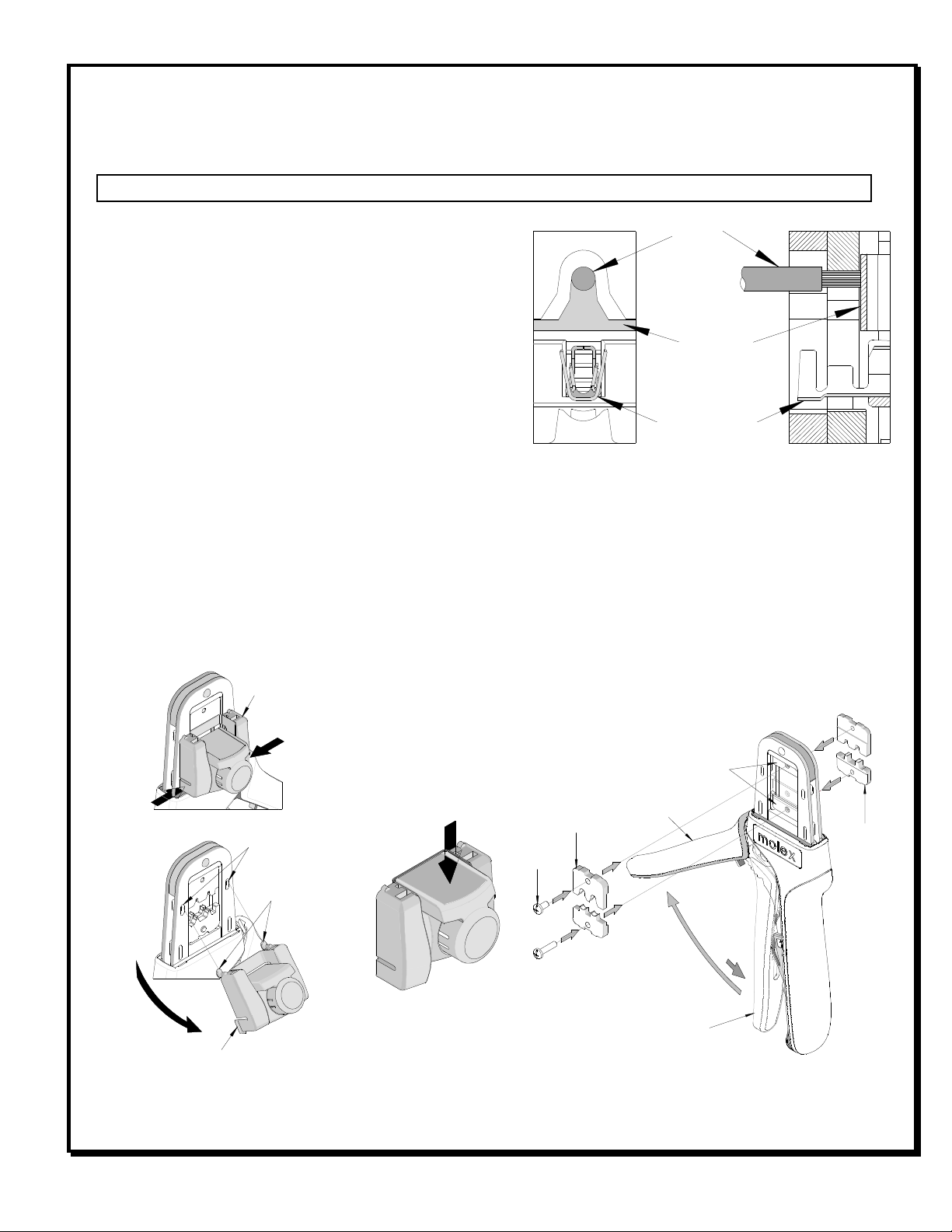
Right or Left Hand Operation
This hand tool has an added feature that can be converted
from a right handed application to a left handed
application. It is necessary to reverse the tooling if using
the left handed application along with the locator. Follow
the steps below:
1. The locator must be removed before reversing the
tooling.
2. Remove the M BHCS which is holding the upper tooling.
. Flip the upper tooling to the opposite side and replace the M BHCS.
Make sure the small markings on the front and back of the hand tool
frame, match up and are on the outside of the hand tool frame. See Figure
8 and 9.
4. Do the same thing with the lower tooling and tighten the M screws. Be
sure the small markings line up.
5. Reinstall the locator by following the Instructions in the locator replacement
section.
Maintenan e
It is recommended that each operator of the tool be made aware of, and
responsible for, the following maintenance steps:
1. Remove dust, moisture, and other contaminants with a clean brush, or
soft, lint free cloth.
2. Do not use any abrasive materials that could damage the tool.
. Make certain all pins; pivot points and bearing surfaces are protected with a thin coat of high quality machine
oil. Do not oil excessively. The tool was engineered for durability but like any other equipment it needs
cleaning and lubrication for a maximum service life of trouble free crimping. Light oil (such as 0 weight
automotive oil) used at the oil points, every 5,000 crimps or months, will
significantly enhance the tool life.
4. Wipe excess oil from hand tool, particularly from crimping area. Oil
transferred from the crimping area onto certain terminations may affect
the electrical characteristics of an application.
5. When tool is not in use, keep the handles closed to prevent objects from
becoming lodged in the crimping dies, and store the tool in a clean, dry
area.
Mis rimps or Jams
Should this tool ever become stuck or jammed in a partially closed position,
Do Not force the handles open or closed. The tool will open easily by pressing up on the ratchet release lever in
the movable handle. See Figure 11.
(BOTH SIDES) LIGHT OIL
(EVERY 3 MONTHS OR
5,000 CRIMPS)
LEVER
Figure 11