Hand Crimp Tool for SPOX™Terminals
Doc No. 63811-5200 Release Date: 04-03-06 UNCONTROLLED COPY Page 2 of 6
Revision: A Revision Date: 04-03-06
CONDITIONS:
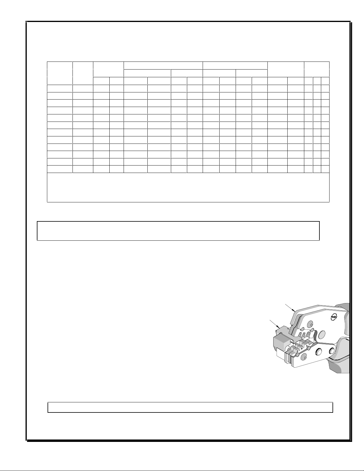
After crimping, the conductor profiles should measure the following (see notes on page 5).
Conductor Crimp Insulation Crimp
Wire Size Height (Ref.) Width (Ref.) Height (Ref.) Width (Ref.) Pull Force Min. ✴ Profile
Terminal
Series No
Hand
Tool
Locator AWG mm2mm In. mm In. mm In. mm In. N Lb. A B C
5103 1 22 0.35 0.73-0.80 .029-.031 1.40 .055 1.68 .066 1.90 .075 44.48 10.0 X
5103 1 24 0.20 0.67-0.74 .026-.029 1.40 .055 1.57 .062 1.90 .075 28.91 6.5 X
5103 1 26 0.12 0.63-0.69 .025-.027 1.40 .055 1.42 .056 1.50 .059 17.79 4.0 X
5103 1 28 0.08 0.61-0.67 .024-.026 1.40 .055 1.42 .056 1.50 .059 11.12 2.5 X
5263 1 22 0.35 0.73-0.80 .029-.031 1.40 .055 1.68 .066 1.90 .075 44.48 10.0 X
5263 1 24 0.20 0.67-0.74 .026-.029 1.40 .055 1.57 .062 1.90 .075 28.91 6.5 X
5263 1 26 0.12 0.63-0.69 .025-.027 1.40 .055 1.42 .056 1.50 .059 17.79 4.0 X
5263 1 28 0.08 0.61-0.67 .024-.026 1.40 .055 1.42 .056 1.50 .059 11.12 2.5 X
45627 2 22 0.35 0.73-0.80 .029-.031 1.40 .055 1.68 .066 1.90 .075 44.48 10.0 X
45627 2 24 0.20 0.67-0.74 .026-.029 1.40 .055 1.57 .062 1.90 .075 28.91 6.5 X
✴ To Achieve IPC-A-620 Class 2 crimps. The following over-all wire insulation diameter ranges are recommended:
1. Profile A: 1.20-1.90mm (.047-.075 inch)
2. Profile B: 1.20-1.55mm (.047-.061 inch)
3. Profile C: 1.15-1.30mm (.045-.051 inch)
OPERATION
CAUTION: Install only Molex terminals listed above with this tool. Do not crimp hardened objects as damage can occur to
the tool or die.
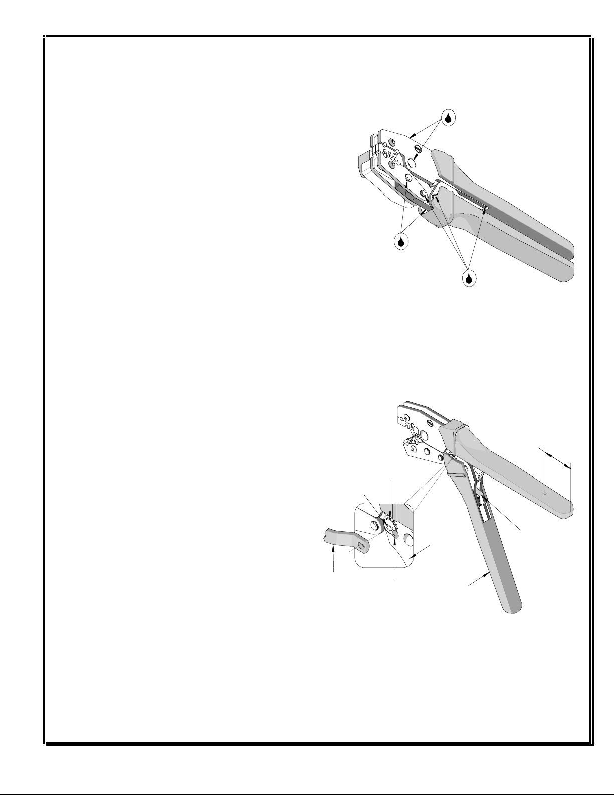
Open the tool by squeezing the handles together, at the end of the closing stroke, the ratchet mechanism will release the handles, and
the hand tool will spring open.
Crimping Terminals
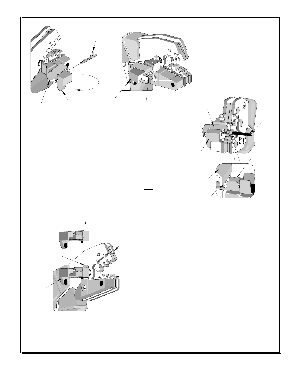
1. Select the desired terminal listed in the preceding charts. Make sure that the proper locator is mounted on the tool.
2. Swing the terminal locator away from the crimp tool shown in Figure 2. Some terminals
with large insulation grips may interfere with the crimp tooling when swinging the
locator into position. The terminal must then be loaded into the locator in the
closed/crimp position.
3. When using the locator, press down on the wire stop on the locator as shown in Figure
2. Insert the proper terminal into the proper nest opening. Make sure when choosing
the nest opening, it will correspond with the A, B, or C profile on the hand tool.
4. Return the locator to its original position.
5. Insert the proper wire over the terminal. Some large O.D. wires may need to be placed
into the terminal before closing the tool. Gently touch the wire stop with the end of the
wire. See Figure 3.
6. Compress the terminal by squeezing the tool handles until the ratchet mechanism cycle
has been completed. Release handles to open the jaws.
Note: The tamper proof ratchet action will not release the tool until it has been fully closed.
Figure 1
LOCATOR
JAWS OPEN