Molnar Hoist UNIVERSAL M245-A User manual

UNIVERSAL
OPERATION
Operation Manual for Molnar
Hoists Two Post Hoist (4.5 Tonne)
M245-A
Updated 8 December 2015

CONTENTS
INTRODUCTION..........................................................................................................................................2
OVERVIEW..................................................................................................................................................3
SAFETY PRECAUTIONS.............................................................................................................................4
LOADING VEHICLES...................................................................................................................................6
UNLOADING VEHICLES..............................................................................................................................6
VEHICLE POSITIONING GUIDELINES .......................................................................................................7
OPERATING INSTRUCTIONS.....................................................................................................................8
MAINTENANCE ...........................................................................................................................................9
BALANCE CABLE ADJUSTMENT .............................................................................................................12
TECHNICIAN MAINTENANCE SCHEDULE...............................................................................................13
TROUBLE SHOOTING...............................................................................................................................14
1

INTRODUCTION
This Operation Manual has been written for the safe use and maintenance of Molnar M245
‘Universal’ Two Post Hoists.
Molnar Hoist M245-A-SSSSSS “Universal”
Molnar Hoists vehicle hoists, parts and accessories; made in Australia and built to the highest
safety standards. The Molnar M245 ‘Universal’ Two Post Hoist is intended for use in commercial
workshops for wheels free lifting of a wide range of cars and automotive vehicles. Two Post Hoists
are designed to optimise workshop clear floor space for ease of access, cleaning and freedom of
movement for equipment.
All operators should familiarise themselves with this manual before operation of the vehicle hoist.
A copy should always be readily available for operators to refer to if and when required.
As the policy of Molnar Hoists is one of continuous improvement, the manufacturer reserves the
right to change specifications without notice. Information is correct and true at time of printing.
Updated 8 December 2015
2

OVERVIEW
Operators should familiarise themselves with the vehicle hoist shown here in Diagrams 1A & 1B.
Diagram 1A – Top Down View of M245 Hoist
Diagram 1B – Isometric View of M245 Hoist
FRONT
REAR
DRIVE IN
DIRECTION
CONTROL
POST
(LEFT HAND
SIDE)
NON-CONTROL
POST
(RIGHT HAND
SIDE)
CONTROLS
POWER UNIT
CONTROLS
POWER
UNIT
CONTROL POST
(LEFT HAND SIDE)
NON-CONTROL POST
(RIGHT HAND SIDE)
TOP
BRACE
3

SAFETY PRECAUTIONS
For your own safety and the safety of equipment, always take the following precautions
Failure to comply with these precautions may result in loss of load, damage to unit and/or personal injury
Ensure you carefully
read and understand
the Operation and
Safety Instructions
detailed in this Manual
before using the hoist.
Load must be locked
at all times, except
when raising or
lowering.
Use vehicle
manufacturer’s
recommended pick-up
points. All 4 pick-up
pads must support the
load.
Not recommended for
vehicles with weight
distribution ratios
greater than 60:40.
Monitor vehicle, hoist
and area for
obstructions and/or
personnel before use
and during operation.
Vehicle’s centre of
gravity must be within
the pick-up pad area.
Ideally the centre of
gravity should be in
line with the rear edge
of the posts.
Maximum capacity.
4.5 tonnes (4500kg)
Do not exceed 1125
kg per arm
Not recommended
where the distance
between pick-up points
is less than 33% (one-
third) of the vehicle’s
length.
Perform risk
assessment before
attempting to lift
loaded vehicles.
Do not attempt to
operate hoist from
under the vehicle.
Ensure pre-operation
checks are carried out
before use
Do not oil or grease
the lifting arm
assemblies.
4
!✔
✔

Regular service and
maintenance to be
carried out as
described in the
Service Manual.
Failure to do so may
void warranty and
cause risk of injury.
Do not try to adjust
relief valve as it has
been set at maximum
operating efficiency.
This vehicle hoist is
not designed to be
used in & around
steam cleaning nor be
installed in the open,
exposed to the
elements. Hoist
operated in such
conditions are not
covered by our
warranty.
Do not force safety
release lever into the
off position while
weight is resting on the
carriage safety locks.
In moist conditions,
ensure moving
components are well
lubricated.
To prevent rust in the
cylinder, raise the hoist
to full height and leave
it there when not in
use.
Seal and protect all
electrical components
from element.
Remove brake fluid
spills immediately as
they will damage the
powder coat. Clean
the hoist with warm
water and non
abrasive pH neutral
detergents. Surfaces
should be thoroughly
rinsed to remove
residue. After floor
cleaning, thoroughly
rinse base of the hoist
to remove residue.
Use only
recommended wire
rope lubricants
Do not make any
changes to safety
equipment.
Always use safety
supports when
removing or installing
heavy components.
Do not operate if
damaged.
5

LOADING VEHICLES
1. Ensure the hoist is fully lowered, the lifting arms are positioned out of the way and the area is clear
of obstructions and/or personnel before use.
2. Check the weight and weight distribution of the vehicle and review key areas;
a. Where is the engine located?
b. Is it front wheel drive, rear wheel drive or four wheel drive?
c. Is the vehicle heavily loaded?
d. Are there accessories fitted such as bull bars, wheels, fuel tanks, racks etc.
Refer to Vehicle Positioning Guidelines for more details on positioning vehicles
3. Drive the vehicle in so it is central between the posts. If required, use a spotter to guide you but
ensure the spotter is never directly in the vehicle’s path.
4. Position the vehicle so the centre of gravity is as close as possible to the rear edge of the posts.
5. Secure the vehicle to prevent it from rolling.
6. Position the lifting arms under the vehicle and position the pick-up pads underneath the vehicle’s
pick-up points.
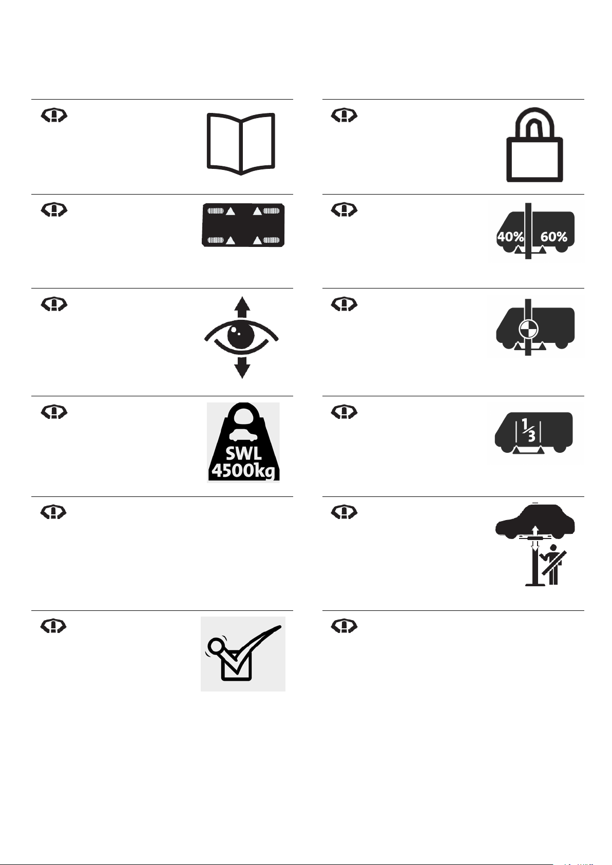
Note: The vehicle manufacturer’s pick-up points may be indicated with triangle shaped markings.
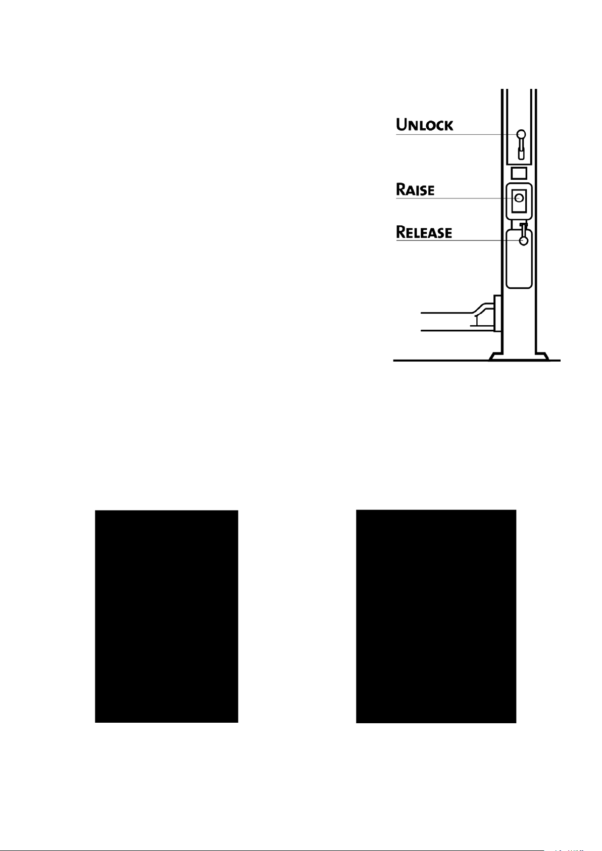
7. Adjust the pick-up pads so they are as close to the pick-up points as possible, this may require
fitting extension adaptors. See Diagrams 2A & 2B
Diagram 2A – Pick-up pad adjusted down to its
minimum height Diagram 2B - Pick-up pad on extension adaptor and
adjusted up to its maximum height.
UNLOADING VEHICLES
1. Lower vehicle hoist to the ground.
2. Lower pick-up pads and remove extension adaptors.
3. Position lifting arms out of the way of the vehicle.
4. Drive the vehicle away from the hoist. If required, use a spotter to guide you but ensure the spotter
is never directly in the vehicle’s path.
6

VEHICLE POSITIONING GUIDELINES
These guidelines are for positioning the majority of Passenger and Commercial vehicles on a Molnar M245
‘Universal’ Two Post vehicle hoist, each vehicle is different so the operator will be required to do their own
risk assessment prior to lifting.
General Pre-Lifting Checks:
•Check the vehicle for loads carried
•Check accessories/options fitted
•Check the size and weight of the wheels
•Check the Wheelbase and Vehicle length
•Check the drive-train
•Check the vehicle design for weight distribution and centre of gravity.
•Check if the vehicle needs to be driven on forwards or backwards.
•Check Manufacturers recommended lifting points
Passenger Car or Utility Vehicle
Positioning Commercial Vehicle
Positioning
Begin by aligning Side Mirrors and Steering
Wheel in line with the Posts.
The Centre of Gravity should approximately be
the driver’s position in the vehicle.
Begin by aligning the Rear Edge of the Driver’s
Door with the Posts.
The Centre of Gravity should approximately be
the mid-point of the vehicle.
For asymmetric loading, vehicle Centre of Gravity should be just to the rear of the posts
Always Check stability of vehicle on the hoist at a low height before working
underneath; reposition the vehicle if it is not stable.
?
7

OPERATING INSTRUCTIONS
Instructions on operation of vehicle hoist; refer to Diagram 3 for controls.
TO RAISE 1. To raise the vehicle hoist, press and hold the
Raise Button.
2. When the pick-up pads are just contacting the
vehicle, check the pick-up pads for location
and contact, the arms for clearance and the
arm locks for full engagement (refer to
Diagrams 4A & 4B).
3. Raise the vehicle only until the tyres are at
least 150mm clear of the floor. At this point,
check the weight balance of the vehicle and its
support on the ads. If not secure, lower vehicle
hoist to the ground and repeat steps 1 to 3.
Note: another lifting method may be required if
vehicle cannot be securely supported on a two
post lift.
4. Raise vehicle to desired height, release raise
button and lock the hoist.
Note: Locks should make an audible clicking
sound during raising, if sound not heard, lower
vehicle hoist to ground, remove vehicle and do
not use until rectified.
Diagram 3 – Operating Controls
TO LOCK 1. Hold down Release Lever until the locks hold
the load of the vehicle.
TO LOWER 1. Ensure the area is clear of obstructions and/or
personnel.
2. Raise the hoist approximately 50mm
3. Hold down the Unlock Lever then hold down
the Release Lever.
Diagram 4A – Arm Lock fully disengaged Diagram 4B – Arm Lock fully engaged.
8

MAINTENANCE
Requirements of the Operator to keep the vehicle hoist in safe, good working order and maintain warranty.
Owner Maintenance Schedule
It is the Hoists Owner’s responsibility and Duty of care to maintain the hoist.
This must be recorded and retained.
Pre-Operational
Monthly
6 Monthly
Visual Inspections
>Access and Clearance
>Work area clean & tidy
>Structure
>Loose or damaged parts
>Decals & control markings
>Pick-up pads
>Hydraulic fluid levels
Functional Inspections
>Operating controls
>Carriage locks
>Arm locks
>Unusual noise or vibration
Check Accessories
Visual Inspections
>Flooring
>Anchor bolts
>Structural alignment
>Structural integrity
>Visual appearance
>Operation manual
>Displayed notices
>Compliant Clearance
>Pick-up pads
>Balance cables
>Hydraulic System Leaks
>Pulleys
Functional Inspections
>Lubrication
>Isolation switch
>Limit switch
Check Accessories
Visual Inspections
>Oil leaks from cylinders
>Oil leaks from pipe joints
Functional Inspections
>Installation check
Note: Service intervals are based on an average operation of 8 lifts per day, 5 days per week, 50 weeks per
year (2,000 cycles). If operation cycles are more frequent, the service and inspection frequency should
reviewed and set at an appropriate level with your Technician. The intervals shown are the minimum time
periods for inspections.
9

Owner Maintenance Information
PRE-OPERATIONAL INSPECTIONS
Pre-operational inspections should be conducted before the start of each shift.
Pre-Operational Visual Inspection
•ACCESS & CLEARANCE: Ensure there are no obstructions around the hoist (or vehicles when on the hoist)
that could prevent operators working safely on and around the hoist and vehicle.
•WORK AREA CLEAN & TIDY: The work area should be clean and tidy prior to operation to eliminate the risk
of slips and trip hazards, i.e. oil, parts, tools, hoses, etc.
•STRUCTURE: A visual inspection of the structure for anomalies that may indicate damage or deterioration.
Anomalies must be reported to the authorised person. Only an authorised person may assess the condition of
the structure. The result of this assessment must be reported and recorded.
•LOOSE OR DAMAGED PARTS: A visual inspection of hoist components for anomalies that may indicate
parts are damaged or loose. The result of this assessment must be reported and recorded.
•DECALS & CONTROL MARKINGS: Check to see that the hoist’s decals and markings for controls are not
only present, but are in a good, clean condition and clearly visible.
•PICK UP PADS: Check condition of pick up pads to ensure they are clean, the material and structure is in
good condition, and not excessively worn or otherwise damaged.
•HYDRAULIC FLUID LEVELS: Check the amount of hydraulic fluid in the system is within the correct limits.
Daily Functional Inspection
•OPERATING CONTROLS: Operating controls should be tested by activating through the full range of
operation.
•CARRIAGE LOCKS: Without a vehicle on the hoist, raise the hoist 500mm while listening for the locking
toggles, the toggles in both posts should click in unison. Lower the hoist back to the ground to ensuring the
locking toggles are properly disengaging.
•ARM LOCKS: With the hoist fully lowered, check the arms locks have properly disengaged by checking if all
lift arms pivot freely. Raise the hoist 200mm and check the arm locks have properly engaged by trying to pivot
all lift arms and checking that the arm locks prevent the lift arms from pivoting.
•UNUSUAL NOISE OR VIBRATION: If during operation, unusual noise or vibration is detected, it must be
reported and treated as a potential fault.
•ACCESSORIES: Accessories should undergo the same visual and functional inspection as the hoist.
MONTHLY INSPECTIONS
In addition to pre-operational inspections, more in depth inspections should be conducted every month.
Monthly Visual Inspections
•FLOORING: Check condition of floor area where the hoist is mounted, i.e. is not cracked or crumbling,
especially in the region surround anchor bolts.
•ANCHOR BOLTS: Check the anchor bolts are secure in the concrete , anchor bolts must be tight and are not
excessively corroded or otherwise deteriorated or damaged.
•STURCUTAL INTEGRITY: Visually check the physical condition of the structure components for damage,
deformation, corrosion or any other signs of deterioration.
•VISUAL APPEARANCE: Check the overall appearance of the hoist for damage, signs of deterioration or other
potential indicators of faults or hazards.
•OPERATORS MANUAL AVAILABLE: The operator’s manual for the hoist must be available , in good
condition and easily accessible to operators.
•DISPLAYED NOTICES: Critical hoist information needs to be displayed on the hoist clearly, easily visible and
legible for operators;
oOperating Instructions: Details on how to safely operate the hoist.
oSafe Working Load of the hoist
oLoad Distribution is how the vehicle should be loaded safely on the hoist.
•COMPLIANT CLEARANCE: Ensure there are no temporary or permanent obstructions around the hoist or
vehicles on the hoist that that encroach into the safe area clearance limits.
10

•BALANCE CABLES: The balance cables must be visually checked for signs of deterioration and if necessary,
cleaned and re-lubricated.
•HYDRAULIC SYSTEM LEAKS: After the operational check, the areas of the hydraulic circuit must be
inspected for leaks. Evidence of fluid on the hoist can be a sign of a potential fault.
•PULLEYS: Visually check rotation during raising and lowering of the hoist.
If pulleys are not rotating freely, pulleys must be removed/inspected/replaced by an
authorised service agent.
Monthly Functional Inspections
•LUBRICATION: All lubrication points must be inspected and re-lubricated as required.
•ISOLATION SWITCH: Confirm that there is an appropriate isolation witch to allow the hoist to be safely
isolated and locked out to prevent accidental or unwanted operation.
•LIMIT SWITCH: Ensure the limit switch prevents the operation of the hoist beyond the limits of travel.
•ACCESSORIES: Accessories should undergo the same visual and functional inspection as the hoist.
6 MONTHLY INSPECTIONS
In addition to monthly inspections, other inspections should be conducted every 6 months.
6 Monthly Visual Inspections
•Check for oil leaks from cylinders. If leaks are detected, call your service provider.
•Check for oil leaks around pipe joints in the posts and tank. If leaks are detected, tighten oil fittings.
6 Monthly Functional Inspections
•Check Installation;
1. Rock the hoist to check any movement.
2. Use a spirit level to ensure posts are vertical in both axes.
3. Visually inspect anchor bolts.
4. Ensure anchor bolts are tight to 155Nm torque.
5. Check that the shimming of the hoist is secure and in good condition.
11

BALANCE CABLE ADJUSTMENT
Note; this procedure must be followed exactly to ensure the correct amount of tension on the cables. If
cables are too loose the vehicle could become unstable and if too tight damage to the cable could occur.
1. Raise the hoist 50mm off the locks and release the safety locks and lower the hoist to within 120mm
of the bottom.
2. Using 2 of the 90mm pad adjusters, place between the carriage and base plate. Lower the hoist
until carriages are sitting on the adaptors; refer to Diagram 5
3. On the control side, hold the cable swage at the top of the
safety rack (the swage is a hex and will take a 14mm
open-ended spanner) tighten the cable nylock nut (24 mm
deep socket and ratchet) until the pad adaptor under the
non-control carriage IS JUST MOVABLE
4. On the non-control side, hold the swage at the top of the
safety rack and tighten the cable nylock nut until the
adaptor under the carriage on this side has stopped
moving.
5. Run the hoist up and listen to the synchronisation of the
lock engagement.
6. Adjust the cable nut on the “high” side until the locks are
in Unison.
7. Remove the 90mm pad adaptors
Diagram 5 – Using Pad Adaptors for Gauging
Balance Cable Adjustment
12

TECHNICIAN MAINTENANCE SCHEDULE (detailed in the Service Manual)
Requirements of the Service Technician to keep the vehicle hoist in safe, good working order and maintain
warranty.
Service and safety inspections on the hoist must be performed by a competent person.
This must be recorded and maintained.
In the first 6 Weeks
Every Year Every 2 Years Every 10 Years
>Replace the
hydraulic oil
>Readjust the balance
cables
>Safety operation test
>Balance cable
inspection,
adjustment and
lubrication
>Lubricate pulleys
>Lifting arms, pivot
pins
>Pick-up pads
>Hydraulic oil and
system
>Electrical controls
and limit switch
>Structural & general
check
>Accessories
condition
In addition to regular
Yearly tasks
>Replace the
hydraulic oil
>Clean tank and filter
In addition to regular
Yearly and 2 Yearly
tasks
>Replace pick-up pad
rubbers
>Balance cables and
pulleys; removal and
inspection
The first oil change
should occur within the
first 6 weeks of operation
to keep the hydraulic
system in good working
condition.
Although recommended,
this is not mandatory.
If the yearly service and
safety inspection is not
performed, the warranty
is null and void.
To keep the hydraulic
system in good working
condition, oil changes
are required every 2
years or 4,000 cycles.
After 10 years of service,
remove the balance
cables and pulleys from
the hoist, clean and
inspect them to ascertain
serviceability, replace if
required. If the hoist is in
a high working or
extreme environment,
the balance cables
should be replaced.
13

TROUBLE SHOOTING
Q ! A
Shuddering/shaking
or sound of abrasion
from posts during
raising or lowering.
Guide Blocks Dry Apply General Purpose Grease to Guide
Tracks.
Vehicle Weight is too far
towards the front of the hoist. Lower vehicle and reposition, refer to
Positioning Vehicles section.
Hoist not staying up Lowering Handle Sticking Lubricate Lowering Handle Pivot
Contaminated Oil blocking
valves Change Oil
Faulty Control Valve Contact Service Technician
Hoist Not Locking Hoist won’t lock in low height Hoist must be raised a minimum of 350mm for
Carriage Locks to engage
Motor will not run No Power Supply Check Circuit Breakers
Limit switch stuck Check operation of limit switch and limit switch
actuator.
Faulty Contactor Contactor should be replaced*
Motor runs but will
not lift Incorrect Phase wiring Change rotation of motor*
Lowering Handle Sticking Lubricate Lowering Handle Pivot
Hoist overloaded Remove vehicle
Carriages not
horizontal Balance cables need adjustment Refer to Balance Cable Adjustment section for
procedure or contact Service Technician.
Balance cables need replacing If balance cable(s) are damaged, contact a
Service Technician to replace.
Oil Leaks Loose fittings Tighten fittings
Faulty fittings Replace fittings
Leaking Hydraulic Cylinder Contact your service provider
Hoist will not lift to
maximum height Low hydraulic oil level Top up hydraulic oil
* To be performed by a
Qualified Electrician only.
14

For more information, please contact us or your local Molnar Representative
16-20 Coglin Street Brompton SA 5007 Australia
T 08 7120 8700 F 08 8346 0097 E inf[email protected]
www.molnarhoists.com.au
onwards & upwards
Other manuals for Hoist UNIVERSAL M245-A
1
Table of contents
Other Molnar Industrial Equipment manuals