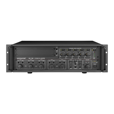
Monacor CARPOWER Power-4/600 User manual

Power-4/600
Best.-Nr. 14.2640
Montageanleitung • Mounting instructions
Notice d’utilisation • Istruzioni per il montaggio
Montage-instructie • Manual de instrucciones
Instrukcja montazowa • Sikkerhedsoplysninger
Säkerhetsföreskrifter • Turvallisuudesta
4-Kanal-Car-HiFi-Endstufe
4-Channel Car HiFi Power Amplifier
Amplificateur Hi-Fi Embarquée, 4 Canaux
Finale Di Potenza HiFi A 4 Canali Per Auto
•

2
www.carpower.com
Vor der Montage ...
Wir wünschen Ihnen viel Spaß mit dem neuen Gerät von
CARPOWER. Bitte lesen Sie diese Montageanleitung
vor dem Betrieb gründlich durch. Die Anleitung soll Ihnen
eine schnelle und einfache Montage ermöglichen. Sie
finden dazu hier alle nötigen Informationen. Durch die
Beachtung der Anleitung werden außerdem eventuelle
Schäden am Gerät durch unsachgemäße Montage ver-
mieden. Heben Sie die Anleitung für ein späteres Nach-
lesen auf.
Der deutsche Text beginnt auf der Seite 4.
Prior to Mounting ...
We wish you much pleasure with the new unit by CAR-
POWER. Please read these operating instructions care-
fully prior to operating the unit. With these operating in-
structions a quick and easy mounting will be possible.
You will find all necessary information here. By following
these instructions possible damage to the unit due to
improper mounting will be prevented. Please keep the
operating instructions for later use.
The English text starts on page 4.
D
A
CH
GB
Avant toute installation ...
Nous vous souhaitons beaucoup de plaisir à utiliser cet
appareil CARPOWER. Lisez ce mode d'emploi entière-
ment avant toute utilisation. Cette notice a pour objectif
de faciliter le montage. Vous y trouverez toutes les
informations nécessaires. En outre, en respectant les
conseils donnés, vous éviterez tout mauvais montage et
donc dʼendommager lʼappareil. Conservez la notice pour
pouvoir vous y reporter ultérieurement.
La version française se trouve page 10.
Prima del montaggio ...
Vi auguriamo buon divertimento con il vostro nuovo
apparecchio CARPOWER. Leggete attentamente le
istruzioni prima di mettere in funzione l'apparecchio. Le
istruzioni che contengono tutte le informazioni necessa-
rie Vi permettono un montaggio rapido e semplice. Ri-
spettando quanto spiegato nelle istruzioni evitate even-
tuali danni allʼapparecchio in seguito ad un montaggio
non a regola dʼarte. Conservate le istruzioni per poterle
consultare anche in futuro.
Il testo italiano inizia a pagina 10.
F
B
CH
I
Przed uruchomieniem ...
Życzymy Państwu zadowolenia z nowego produktu
CARPOWER. Dzięki tej instrukcji montażu, będą pań-
stwo w stanie poznać wszystkie funkcje tego urządzenia.
Dzięki tej instrukcji obsługi będą Państwo w stanie
poznać wszystkie funkcje urządzenia. Stosując się do
instrukcji unikną państwo błędów i ewentualnego uszko-
dzenia urządzenia na skutek nieprawidłowego użytko-
wania. Prosimy zachować instrukcję.
Tekst polski zaczyna się na stronie 22.
Antes del montaje …
Tenemos de agradercerle el haber acquirido un equipo
CARPOWER y le deseamos un agradable a montar este
equipo fácilmente. Por favor, lea esta manual de instruc-
ciones atentamente antes de hacer funcionar el aparato.
Todos los informaciones necesarios están incluidos.
Para observar las instrucciones daños por un montaje
inadecuado están evitados. Por favor, guarde las ins-
trucciones para una futura utilización.
El texto en español empieza en la página 16.
PL
E
Voor u inschakelt ...
Wij wensen u veel plezier met uw nieuw toestel van
CARPOWER. Lees de handelingen, alvorens het toestel
in gebruik te nemen. Deze handleiding zal u in staat stel-
len alle mogelijkheden van dit toestel te doorgronden.
Door de instructies nauwgezet op te volgen, vermijdt u
bovendien dat het toestel slecht functioneert of dat u
door ondeskundige handelingen uzelf of het toestel
schade toebrengt. Bewaar de handleiding voor latere
raadpleging.
De Nederlandstalige tekst vindt u op pagina 16.
Inden De tænder for apparatet ...
Vi ønsker Dem god fornøjelse med Deres nye CAR-
POWER apparat. Læs oplysningerne for en sikker brug
af apparatet før ibrugtagning. Følg sikkerhedsoplysnin-
gerne for at undgå forkert betjening og for at beskytte
Dem og Deres apparat mod skade på grund af forkert
brug. Gem venligst denne betjeningsvejledning til senere
brug.
Du finder sikkerhedsanvisningen på side 28.
DK
Förskrift
Vi önskar dig mycket nöje med din nya enhet från CAR-
POWER. Läs gärna säkerhetsinstruktionerna innan du
använder enheten. Genom att följa säkerhetsinstruktio-
nerna kan många problem undvikas, vilket annars kan
skada enheten. Spara instruktionerna för framtida
användning.
Du finner säkerhetsinstruktionerna på sidan 28.
SEnnen virran kytkemistä …
Toivomme, että uusi CARPOWER -laitteesi tuo sinulle
paljon iloa ja hyötyä. Ole hyvä ja lue käyttöohjeet ennen
laitteen käyttöönottoa. Luettuasi käyttöohjeet voit käyt-
tää laitetta turvallisesti ja vältyt laitteen väärinkäytöltä.
Ole hyvä ja säilytä käyttöohjeet myöhempää tarvetta var-
ten.
Turvallisuusohjeet löytyvät sivulta 29.
FIN
NL
B

GAIN
60.2
V
HP
15 150
Hz
60.2
V
15 150
Hz
LP
30 150
Hz
30 150
Hz
BASS EQ
dB 180
dB 180
LINE IN
CH
2
1
4
3
INPUT MODE
4 CH 2 CH
POWER
PROTECT
X-OVER
CH
1/2
CH
3/4
PROT PWR
LEVEL
LINE OUT
FULLHP
MONO
LP
+
HP=SUBSONIC
FULLHPLP
+
HP=SUBSONIC
3
1234 56 78 9101112 13
14 15 16 17 18
BRIDGE MODE
POWER IN
+12V GNDREM
SPEAKER
BRIDGE MODE
CH1 CH2 CH 3 CH 4
FUSE 1
FUSE 2
GAIN
6 0.2
V
HP
15 150
Hz
6 0.2
V
15 150
Hz
LP
30 150
Hz
30 150
Hz
BASS EQ
dB 180
dB 180
LINE IN
CH
2
1
4
3
INPUT MODE
4 CH 2 CH
POWER
PROTECT
X-OVER
CH
1/2
CH
3/4
LINE OUT
FULLHP
MONO
LP
+
HP=SUBSONIC
FULLHPLP
+
HP=SUBSONIC
BRIDGE MODE
POWER IN
+12V GNDREM
SPEAKER
BRIDGE MODE
CH1 CH 2 CH3 CH 4
FUSE 1
FUSE 2
Radio
Speaker L
min. 2Ω
Speaker R
min. 2Ω
Fuse 100 A
Chassis
On = 12V
R RearL
12345678
TP
Bass
Tre
EJECT CD/RADIO
AM
FM
CD Menu
LFront R
Rear
Front
Speaker L
min. 2Ω
Speaker R
min. 2Ω
Battery
Chassis
D 4-Kanalbetrieb
GB 4-channel operation
F Mode 4 canaux
I Funzionamento a 4 canali
NL 4-kanaals werking
E Modo 4 canales
PL Praca czterokanałowa
D Aktiver 2-Wegebetrieb
GB Active 2-way operation
F Mode actif 2 voies
I Funzionamento attivo a 2 vie
NL Actieve 2-kanaals werking
E Funcionamiento activo de 2 vías
PL Praca w układzie dwudrożnym aktywnym
GAIN
6 0.2
V
HP
15 150
Hz
6 0.2
V
15 150
Hz
LP
30 150
Hz
30 150
Hz
BASS EQ
dB 180
dB 180
LINE IN
CH
2
1
4
3
INPUT MODE
4 CH 2 CH
POWER
PROTECT
X-OVER
CH
1/2
CH
3/4
LINE OUT
FULLHP
MONO
LP
+
HP=SUBSONIC
FULLHPLP
+
HP=SUBSONIC
BRIDGE MODE
POWER IN
+12V GNDREM
SPEAKER
BRIDGE MODE
CH1 CH 2 CH3 CH 4
FUSE 1
FUSE 2
Radio
Speaker L
min. 2Ω
Speaker R
min. 2Ω
Fuse 100 A
Chassis
On = 12V
12345678
TP
Bass
Tre
EJECT CD/RADIO
AM
FM
CD Menu
LR
Bass
Mid-high range
Speaker L
min. 2Ω
Speaker R
min. 2Ω
Remote control
PROT PWR
LEVEL
Battery
Chassis
GAIN
6 0.2
V
HP
15 150
Hz
6 0.2
V
15 150
Hz
LP
30 150
Hz
30 150
Hz
BASS EQ
dB 180
dB 180
LINE IN
CH
2
1
4
3
INPUT MODE
4 CH 2 CH
POWER
PROTECT
X-OVER
CH
1/2
CH
3/4
LINE OUT
FULLHP
MONO
LP
+
HP=SUBSONIC
FULLHPLP
+
HP=SUBSONIC
BRIDGE MODE
POWER IN
+12V GNDREM
SPEAKER
BRIDGE MODE
CH1 CH 2 CH3 CH 4
FUSE 1
FUSE 2
Radio
Speaker R
min. 4Ω
Fuse 100 A
Chassis
On = 12V
12345678
TP
Bass
Tre
EJECT CD/RADIO
AM
FM
CD Menu
L
Speaker L
min. 4Ω
Battery
Chassis
R
D Alle Kanäle im Brückenbetrieb
GB All channels in bridge operation
F Tous les canaux en mode bridgé
I Tutti i canali con funzionamento a ponte
NL Alle kanalen in brugschakeling
E Todos los canales en modo punteado
PL Wszystkie kanały w układzie mostka
GAIN
6 0.2
V
HP
15 150
Hz
6 0.2
V
15 150
Hz
LP
30 150
Hz
30 150
Hz
BASS EQ
dB 180
dB 180
LINE IN
CH
2
1
4
3
INPUT MODE
4 CH 2 CH
POWER
PROTECT
X-OVER
CH
1/2
CH
3/4
LINE OUT
FULLHP
MONO
LP
+
HP=SUBSONIC
FULLHPLP
+
HP=SUBSONIC
BRIDGE MODE
POWER IN
+12V GNDREM
SPEAKER
BRIDGE MODE
CH1 CH 2 CH3 CH 4
FUSE 1
FUSE 2
Radio
Subwoofer
min. 4Ω
Fuse 100 A
Chassis
On = 12V
12345678
TP
Bass
Tre
EJECT CD/RADIO
AM
FM
CD Menu
LR
Speaker L
min. 2Ω
Speaker R
min. 2Ω
Remote control
PROT PWR
LEVEL
Battery
Chassis
D 3-Kanalbetrieb
GB 3-channel operation
F Mode 3 canaux
I Funzionamento a 3 canali
NL 3-kanaals werking
E Modo 3 canales
PL Praca trójkanałowa

Bitte klappen Sie die Seite 3 heraus. Sie sehen
dann immer die beschriebenen Bedienelemente
und Anschlüsse.
Inhalt
1 Übersicht der Bedienelemente und
Anschlüsse . . . . . . . . . . . . . . . . . . . . . . . . . 4
1.1 Frontseite . . . . . . . . . . . . . . . . . . . . . . . . . . . 4
1.2 Rückseite . . . . . . . . . . . . . . . . . . . . . . . . . . . 4
2 Sicherheitshinweise . . . . . . . . . . . . . . . . . . 5
3 Vorsicht bei hohen Lautstärken . . . . . . . . 5
4 Einsatzmöglichkeiten . . . . . . . . . . . . . . . . . 5
5 Montage . . . . . . . . . . . . . . . . . . . . . . . . . . . . 5
6 Endstufe anschließen . . . . . . . . . . . . . . . . 5
6.1 Stromversorgung . . . . . . . . . . . . . . . . . . . . . 5
6.1.1 Betriebsspannung . . . . . . . . . . . . . . . . . . . 5
6.1.2 Masseanschluss . . . . . . . . . . . . . . . . . . . . 6
6.1.3 Steuerspannung zum Einschalten . . . . . . 6
6.2 Eingänge . . . . . . . . . . . . . . . . . . . . . . . . . . . 6
6.2.1 4-Kanalbetrieb . . . . . . . . . . . . . . . . . . . . . . 6
6.2.2 Aktiver 2-Wegebetrieb . . . . . . . . . . . . . . . . 6
6.2.3 Brückenbetrieb . . . . . . . . . . . . . . . . . . . . . 6
6.2.4 3-Kanalbetrieb . . . . . . . . . . . . . . . . . . . . . . 6
6.3 Ausgang für einen Subwoofer-Verstärker . . . 6
6.4 Lautsprecher . . . . . . . . . . . . . . . . . . . . . . . . . 6
6.4.1 4-Kanalbetrieb . . . . . . . . . . . . . . . . . . . . . . 7
6.4.2 Aktiver 2-Wegebetrieb . . . . . . . . . . . . . . . . 7
6.4.3 Brückenbetrieb . . . . . . . . . . . . . . . . . . . . . 7
6.4.4 3-Kanalbetrieb . . . . . . . . . . . . . . . . . . . . . . 7
6.5 Fernbedienung . . . . . . . . . . . . . . . . . . . . . . . 7
7 Inbetriebnahme . . . . . . . . . . . . . . . . . . . . . . 7
7.1 Filter auswählen und
Trennfrequenzen einstellen . . . . . . . . . . . . . 7
7.2 Pegel und Bassanhebung einstellen . . . . . . 8
8 Fehlerbeseitigung . . . . . . . . . . . . . . . . . . . . 8
9 Technische Daten . . . . . . . . . . . . . . . . . . . . 9
1 Übersicht der Bedienelemente
und Anschlüsse
1.1 Frontseite
1Betriebsanzeige POWER
2Anzeige PROTECT leuchtet bei aktivierter
Schutzschaltung:
1. wenn an einem der Lautsprecherausgänge
(14) ein Kurzschluss aufgetreten ist
2. wenn die Endstufe überhitzt ist
3Trimmregler BASS EQ zur Bassanhebung bis
18 dB bei 45 Hz:
oberer Regler für die Kanäle 3 und 4,
unterer Regler für die Kanäle 1 und 2
4Schalter X-OVER zur Auswahl der Filter:
oberer Schalter für die Kanäle 3 und 4,
unterer Schalter für die Kanäle 1 und 2
LP für Basslautsprecher oder einen Sub-
woofer, Tiefpass eingeschaltet
HP für Mittelhochtöner, Hochpass einge-
schaltet
FULL für Full-Range-Lautsprecher, kein Filter
eingeschaltet
5Trimmregler LP zum Einstellen der Trennfre-
quenz des Tiefpasses:
oberer Regler für die Kanäle 3 und 4,
unterer Regler für die Kanäle 1 und 2
6Schalter INPUT MODE
4 CH Alle vier Kanäle werden getrennt über die
Eingänge (10, 11) angesteuert.
2 CH Das Eingangssignal des Kanals 1 wird
auf den Kanal 3 weitergeleitet und das
Eingangssignal des Kanals 2 auf den
Kanal 4.
7Anschluss LEVEL REMOTE für die beiliegende
Fernbedienung (13)
8Trimmregler HP zum Einstellen der Trennfre-
quenz des Hochpasses:
oberer Regler für die Kanäle 3 und 4,
unterer Regler für die Kanäle 1 und 2
Sind in den zugehörigen Kanälen die Tiefpässe
eingeschaltet [Schalter X-OVER (4) in Position
„LP“], wird mit dem Regler die untere Übertra-
gungsfrequenz der Lautsprecher eingestellt. Die
Lautsprecher werden so vor sehr tiefen Frequen-
zen geschützt (Subsonic-Filter).
9Trimmregler GAIN zur Eingangspegelanpas-
sung:
oberer Regler für die Kanäle 3 und 4,
unterer Regler für die Kanäle 1 und 2
10 Cinch-Buchsen für die Eingangssignale der Ka-
näle 1 und 2
11 Cinch-Buchsen für die Eingangssignale der Ka-
näle 3 und 4
12 Cinch-Buchsen LINE OUT zum Anschluss eines
Subwoofer-Verstärkers oder auch zum An-
schluss der Eingänge 3 und 4 (Abb. 6)
An beiden Buchsen liegt das durchgeschleifte
Eingangssignal der Eingänge 1 – 4 in Mono an.
13 Fernbedienung
Mit der Fernbedienung lässt sich die Lautstärke
der Kanäle 3 und 4 verringern, wenn für diese
Kanäle der Tiefpass eingeschaltet ist [oberer
Schalter X-OVER (4) in Position „LP“].
1.2 Rückseite
14 Lautsprecheranschlüsse SPEAKER
15 Sicherungen: 2 × 50 A
Eine durchgebrannte Sicherung nur durch eine
gleichen Typs ersetzen!
16 Anschluss für die Versorgungsspannung +12 V
17 Steuereingang REM zum Einschalten der End-
stufe über eine 12-V-Spannung
18 Masseanschluss GND
Please take out page 3. Then you can always see
the operating elements and connections de-
scribed.
Contents
1 Operating Elements and
Connections . . . . . . . . . . . . . . . . . . . . . . . . 4
1.1 Front panel . . . . . . . . . . . . . . . . . . . . . . . . . . 4
1.2 Rear panel . . . . . . . . . . . . . . . . . . . . . . . . . . 4
2 Safety Notes . . . . . . . . . . . . . . . . . . . . . . . . 5
3 Caution in Case of High Volumes . . . . . . . 5
4 Applications . . . . . . . . . . . . . . . . . . . . . . . . 5
5 Mounting . . . . . . . . . . . . . . . . . . . . . . . . . . . 5
6 Connection of the Power Amplifier . . . . . . 5
6.1 Power supply . . . . . . . . . . . . . . . . . . . . . . . . 5
6.1.1 Operating voltage . . . . . . . . . . . . . . . . . . . 5
6.1.2 Ground connection . . . . . . . . . . . . . . . . . . 6
6.1.3 Control voltage for switching-on . . . . . . . . 6
6.2 Inputs . . . . . . . . . . . . . . . . . . . . . . . . . . . . . . 6
6.2.1 4-channel operation . . . . . . . . . . . . . . . . . 6
6.2.2 Active 2-way operation . . . . . . . . . . . . . . . 6
6.2.3 Bridge operation . . . . . . . . . . . . . . . . . . . . 6
6.2.4 3-channel operation . . . . . . . . . . . . . . . . . 6
6.3 Output for a subwoofer amplifier . . . . . . . . . 6
6.4 Speakers . . . . . . . . . . . . . . . . . . . . . . . . . . . 6
6.4.1 4-channel operation . . . . . . . . . . . . . . . . . 7
6.4.2 Active 2-way operation . . . . . . . . . . . . . . . 7
6.4.3 Bridge operation . . . . . . . . . . . . . . . . . . . . 7
6.4.4 3-channel operation . . . . . . . . . . . . . . . . . 7
6.5 Remote control . . . . . . . . . . . . . . . . . . . . . . . 7
7 Setting into Operation . . . . . . . . . . . . . . . . 7
7.1 Selecting the filters and adjusting the
crossover frequencies . . . . . . . . . . . . . . . . . 7
7.2 Adjusting the level and the bass boosting . . 8
8 Trouble Shooting . . . . . . . . . . . . . . . . . . . . 8
9 Specifications . . . . . . . . . . . . . . . . . . . . . . . 9
1 Operating Elements and Connections
1.1 Front panel
1POWER LED
2LED PROTECT lights up with activated protec-
tive circuit:
1. if a short circuit has occurred at one of the
speaker outputs (14)
2. if the power amplifier is overheated
3Trimming controls BASS EQ for bass boosting
up to 18 dB at 45 Hz:
upper control for channels 3 and 4,
lower control for channels 1 and 2
4Switches X-OVER for selecting the filters:
upper switch for channels 3 and 4,
lower switch for channels 1 and 2
LP for bass speakers or a subwoofer, low
pass switched on
HP for mid-high range speakers, high pass
switched on
FULL for full range speakers, no filter switched
on
5Trimming controls LP for adjusting the crossover
frequency of the low pass:
upper control for channels 3 and 4,
lower control for channels 1 and 2
6Switch INPUT MODE
4 CH All four channels are separately controlled
via the inputs (10, 11).
2 CH The input signal of channel 1 is passed on
to channel 3, and the input signal of chan-
nel 2 to channel 4.
7Connection LEVEL REMOTE for the supplied
remote control (13)
8Trimming controls HP for adjusting the crossover
frequency of the high pass:
upper control for channels 3 and 4,
lower control for channels 1 and 2
If the low passes are switched on in the corre-
sponding channels [switch X-OVER (4) in posi-
tion “LP”], the lower radiation frequency of the
speakers is adjusted with the control. The speak-
ers are thus protected against very low frequen-
cies (subsonic filter).
9Trimming controls GAIN for input level matching:
upper control for channels 3 and 4,
lower control for channels 1 and 2
10 Phono jacks for the input signals of channels 1
and 2
11 Phono jacks for the input signals of channels 3
and 4
12 Phono jacks LINE OUT for connecting a sub-
woofer amplifier or for connecting the inputs 3
and 4 (fig. 6)
The fed-through input signal of the inputs 1 to 4
is available in mono at both jacks.
13 Remote control
The remote control allows to reduce the volume
of channels 3 and 4 if the low pass has been
switched on for these channels [upper switch
X-OVER (4) in position “LP”].
1.2 Rear panel
14 SPEAKER connections
15 Fuses: 2 × 50 A
Only replace a blown fuse by one of the same
type!
16 Connection for the supply voltage +12 V
17 Control input REM for switching on the power
amplifier via a 12 V voltage
18 Ground terminal GND
4
GB
D
A
CH

2 Sicherheitshinweise
Die Endstufe entspricht der Kfz-Richtlinie.
GVerwenden Sie für die Reinigung nur ein trocke-
nes, weiches Tuch, auf keinen Fall Chemikalien
oder Wasser.
GWird das Gerät zweckentfremdet, nicht richtig an-
geschlossen, falsch bedient oder nicht fachgerecht
repariert, kann keine Haftung für daraus resultie-
rende Sach- oder Personenschäden und keine
Garantie für das Gerät übernommen werden.
3 Vorsicht bei hohen Lautstärken
GBei ausgeschaltetem Motor sollte die Car-HiFi-
Anlage nicht längere Zeit mit hoher Lautstärke
betrieben werden. Die Autobatterie wird schnell
entladen und liefert dann eventuell nicht mehr ge-
nügend Energie zum Starten.
4 Einsatzmöglichkeiten
Die Endstufe POWER-4/600 ist speziell für Car-
HiFi-Anlagen konzipiert und kann vier Full-Range-
Lautsprecher (2- oder 3-Wege-Lautsprecher) antrei-
ben. Durch die integrierten Frequenzweichen lässt
sich auch ein aktives 2-Wege-System mit zwei Mit-
telhochtönern und zwei Basslautsprechern oder
einem Subwoofer realisieren (Bi-Amping). Um eine
größere Ausgangsleistung zu erhalten, können die
Kanäle 1, 2 und/oder 3, 4 im Brückenbetrieb jeweils
einen 4-Ω-Lautsprecher antreiben.
5 Montage
Bei der Auswahl des Montageplatzes unbedingt die
folgenden Punkte beachten:
GDas 12-V-Stromversorgungskabel von der Batte-
rie zur Car-HiFi-Endstufe sollte so kurz wie mög-
lich sein. Es ist günstiger, längere Lautsprecher-
kabel zu verwenden und dafür ein kürzeres
Stromversorgungskabel.
GDie Masseleitung von der Endstufe zum Fahrzeug-
chassis sollte ebenfalls so kurz wie möglich sein.
GUm die entstehende Wärme der Car-HiFi-
Endstufe ableiten zu können, muss eine ausrei-
chende Belüftung gewährleistet sein.
GWegen der beim Bremsen auftretenden Kräfte
muss die Endstufe an einer mechanisch stabilen
Stelle fest angeschraubt werden.
GDie Sicherungen und die Regler müssen zugän-
gig sein.
GDie Endstufe sollte elektrisch isoliert vom Fahr-
zeugchassis montiert werden.
Die Endstufe über die vier Befestigungspunkte am
Kühlkörper an geeigneter Stelle festschrauben.
6 Endstufe anschließen
GDer Anschluss der Car-HiFi-Endstufe an das Bord-
netz darf nur durch qualifiziertes Fachpersonal
erfolgen.
GUnbedingt vor dem Anschluss die Minusklemme
der Autobatterie abschrauben, um bei einem
eventuellen Kurzschluss während der Installation
Schäden zu vermeiden.
GDie erforderlichen Kabel so verlegen, dass deren
Isolierung nicht beschädigt werden kann.
Verschiedene Anschlussmöglichkeiten sind in den
Abbildungen 3 – 6 auf der Seite 3 dargestellt.
6.1 Stromversorgung
6.1.1 Betriebsspannung
Den Anschluss „+12V“ (16) über ein entsprechendes
Kabel mit der Plusklemme der Autobatterie verbin-
den. Um den Spannungsverlust durch das Kabel
gering zu halten, sollte mindestens ein Querschnitt
von 20 mm2verwendet werden, z. B. CPC-200/RT*.
Um die neu verlegte 12-V-Leitung gegen einen Kurz-
schluss abzusichern, muss eine 100-A-Vorsicherung
in unmittelbarer Nähe der Batterie zwischengesetzt
werden (max. Kabellänge zur Batterie 20 cm).
Zur Stabilisierung der Betriebsspannung für die
Endstufe und der damit verbundenen Leistungsstei-
ger Zeit als nicht mehr so hoch. Erhöhen Sie
darum eine einmal eingestellte hohe Lautstärke
nach der Gewöhnung nicht weiter.
Während des Autofahrens dürfen Signaltöne, z. B.
von einem Rettungswagen, nicht durch eine zu hohe
Lautstärke der Car-HiFi-Anlage übertönt werden.
VORSICHT Stellen Sie die Lautstärke nie sehr
hoch ein. Extrem hohe Lautstärken
können das Gehör schädigen.
Das Ohr gewöhnt sich an hohe Laut-
stärken und empfindet sie nach eini-
WARNUNG Beim Anschluss der Car-HiFi-End-
stufe an die Autobatterie ist beson-
dere Sorgfalt geboten. Bei Kurz-
schlüssen können sehr gefährlich
hohe Ströme fließen. Schrauben Sie
deshalb unbedingt vor dem Anschluss
die Minusklemme der Autobatterie ab.
Die Endstufe muss fest und fachgerecht an einer
mechanisch stabilen Stelle im Auto montiert wer-
den, damit sie sich nicht löst und zu einem gefähr-
lichen Geschoss wird.
Während des Betriebs kann das Gerät sehr heiß
werden. Platzieren Sie darum keine hitzeempfind-
lichen Gegenstände in der Nähe und berühren Sie
die Endstufe nicht während des Betriebs.
Soll das Gerät endgültig aus dem Betrieb
genommen werden, übergeben Sie es zur
umweltgerechten Entsorgung einem örtli-
chen Recyclingbetrieb.
2 Safety Notes
The power amplifier corresponds to the directive for
automobiles.
GFor cleaning only use a dry, soft cloth, by no
means chemicals or water.
GNo guarantee claims for the unit and no liability for
any resulting personal damage or material damage
will be accepted if the unit is used for other pur-
poses than originally intended, if it is not correctly
connected or operated, or not repaired in an expert
way.
3 Caution in Case of High Volumes
GWith the motor switched off, the car HiFi system
should not be in operation at high volume for a
longer period of time. The car battery will quickly
be discharged, and then it may not be capable any
more of supplying sufficient energy for starting the
car.
4 Applications
The power amplifier POWER-4/600 has especially
been designed for car HiFi systems and is capable
of driving four full range speakers (2-way or 3-way
speakers). Due to the integrated crossover net-
works, it is also possible to realize an active 2-way
system with two mid-high range speakers and two
bass speakers or a subwoofer (bi-amping). To obtain
a higher output power, channels 1, 2 and/or 3, 4 can
drive one 4 Ω speaker each in bridge operation.
5 Mounting
When choosing the place of mounting, always
observe the following items in any case:
GThe 12 V power supply cable from the battery to
the car HiFi power amplifier should be as short as
possible. It is better to use longer speaker cables
and a shorter power supply cable instead.
GThe ground cable from the power amplifier to the
chassis of the car should also be as short as pos-
sible.
GFor carrying off the heat being generated by the
car HiFi power amplifier, a sufficient ventilation
has to be ensured.
GAs forces occur during braking, the power ampli-
fier must tightly be screwed to a mechanically sta-
ble place.
GThe fuses and the controls must be accessible.
GThe power amplifier should be mounted electri-
cally insulated from the car chassis.
Tightly screw the amplifier via the four fixing points
at the heat sink at a suitable place.
6 Connection of the Power Amplifier
GThe connection of the car HiFi power amplifier to
the electric system of the car must only be carried
out by qualified, specialized personnel.
GTo prevent damage in case of a possible short cir-
cuit during installation, prior to the connection it is
indispensable to screw off the negative terminal of
the car battery.
GLay the necessary cables so that their insulation
cannot be damaged.
Various connecting possibilities are shown in figs. 3
to 6 on page 3.
6.1 Power supply
6.1.1 Operating voltage
Connect the terminal “+12V” (16) via a correspond-
ing cable to the positive terminal of the car battery.
To keep the voltage loss by the cable as low as pos-
sible, a minimum cross section of 20 mm2should be
used, e. g. CPC-200/RT*. To protect the newly laid
12 V cable against a short circuit, insert an additional
100 A fuse very close to the battery (max. cable
length to the battery 20 cm).
To stabilize the operating voltage for the power
amplifier and thus the resulting power increase and
sound improvement, a power capacitor is recom-
mended (e. g. CAP-...*).
so high any more after some time. Therefore, do
not further increase a high volume which has once
been adjusted after getting used to it.
While driving in the car, signal sounds, e. g. by an
ambulance, must not be drowned by the volume of
the car HiFi system which has been adjusted too
high.
CAUTION Never adjust the volume very high.
Extremely high volumes may damage
your hearing.
The human ear gets accustomed to
high volumes which do not seem to be
If the unit is to be put out of operation defin-
itively, take it to a local recycling plant for a
disposal which is not harmful to the envi-
ronment.
WARNING When connecting the car HiFi power
amplifier to the car battery, be espe-
cially careful. In case of short circuits
there may be dangerously high cur-
rents. Therefore, prior to the connec-
tion, it is indispensable to screw off the
negative terminal of the car battery.
The power amplifier must be mounted to a me-
chanically stable place in the car. It must be skilful-
ly fixed so that it does not get loose and turn into a
dangerous projectile.
During operation the unit may become very hot.
Therefore, do not place any objects sensitive to
heat close to it and do not touch the power ampli-
fier while in operation.
5
GB
D
A
CH
* von CARPOWER
* by CARPOWER

gerung sowie Klangverbesserung wird ein Power-
Kondensator empfohlen (z. B. CAP-…*).
6.1.2 Masseanschluss
Den Masseanschluss GND (18) über ein Kabel mit
einem Querschnitt von mindestens 20 mm2(z. B.
CPC-200/SW*) mit der Masse des Autos oder bes-
ser direkt mit der Minusklemme der Autobatterie ver-
binden.
Hinweise:
1. Bei Verwendung der Karosserie als Massean-
schluss muss die verwendete Stelle einen guten
elektrischen Kontakt zur Hauptkarosserie aufwei-
sen (z. B. durch ausreichend viele Schweiß-
punkte). Eventueller Lack am Kontaktpunkt muss
vollständig entfernt werden.
2. Zur Vermeidung von Masseschleifen muss die
Masse des Autoradios an die Stelle gelegt wer-
den, an der auch die Endstufe an Masse liegt.
6.1.3 Steuerspannung zum Einschalten
Die Car-HiFi-Endstufe wird durch eine Steuerspan-
nung von +12 V am Anschluss REM (17) ein- und
ausgeschaltet. Den Anschluss REM mit dem 12-V-
Schaltausgang vom Autoradio verbinden (Anschluss
für eine Motorantenne, eventuell mit der Motoran-
tenne parallel schalten).
6.2 Eingänge
Die Endstufe wird über Cinch-Kabel mit den Line-
Ausgängen am Autoradio (oder einer anderen Sig-
nalquelle) verbunden. Sind am Autoradio jedoch
keine Line-Ausgänge vorhanden, können die Laut-
sprecherausgänge des Autoradios über einen
Audio-Übertrager (z. B. FGA-22HQ*) mit den Line-
Eingängen der Endstufe verbunden werden. Der
Anschluss richtet sich nach der gewünschten Be-
triebsart der Endstufe:
6.2.1 4-Kanalbetrieb (Abb. 3)
Der 4-Kanalbetrieb wird beim Einsatz von vier Full-
Range-Lautsprechern (2- oder 3-Wege-Lautspre-
cher) benötigt. Den Schalter INPUT MODE (6) in die
Position „4 CH“ stellen und die Ausgänge des Auto-
radios wie folgt mit den Eingängen LINE IN 1 bis 4
(10, 11) verbinden:
Front links auf Kanal 1
Front rechts auf Kanal 2
Rear links auf Kanal 3
Rear rechts auf Kanal 4
Sind am Autoradio keine Ausgänge für die hinteren
Kanäle (Rear) vorhanden, den Ausgang des linken
Kanals über ein Y-Kabel (z. B. CBA-25/SW*) mit den
Eingangsbuchsen der Kanäle 1 und 3 verbinden und
den Ausgang des rechten Kanals über ein weiteres Y-
Kabel mit den Eingangsbuchsen der Kanäle 2 und 4.
6.2.2 Aktiver 2-Wegebetrieb (Abb. 4)
Beim aktiven 2-Wegebetrieb werden die Mittelhoch-
töner und die Basslautsprecher jeweils von einem
eigenen Verstärkerkanal angetrieben. Den Schalter
INPUT MODE (6) in die Position „2 CH“ stellen und
die Ausgänge des Autoradios mit den Eingängen
LINE IN 1 und 2 (10) verbinden:
linker Kanal auf Kanal 1
rechter Kanal auf Kanal 2
Der Kanal 3 erhält das Signal vom Eingang 1 und
der Kanal 4 vom Eingang 2.
6.2.3 Brückenbetrieb (Abb. 5)
Zur Erhöhung der Ausgangsleistung können die
Kanäle 1 und 2 in Brückenschaltung den linken
Lautsprecher antreiben sowie die Kanäle 3 und 4 in
Brückenschaltung den rechten Lautsprecher. Dazu
den Ausgang des linken Kanals am Autoradio über
ein Y-Kabel (z. B. CBA-25/SW*) mit den Eingängen
LINE IN 1 und 2 (10) verbinden und den Ausgang
des rechten Kanals über ein weiteres Y-Kabel mit
den Eingängen LINE IN 3 und 4 (11). Den Schalter
INPUT MODE (6) in die Position „4 CH“ stellen.
6.2.4 3-Kanalbetrieb (Abb. 6)
Der 3-Kanalbetrieb dient zur Unterstützung von zwei
Full-Range-Lautsprechern durch einen Subwoofer.
Um für den Subwoofer eine höhere Leistung zu er-
halten, werden zwei Kanäle in Brücke geschaltet.
Den Schalter INPUT MODE (6) in die Position „4 CH“
stellen und die Ausgänge des Autoradios wie folgt
mit den Eingängen LINE IN 1 bis 4 (10, 11) verbin-
den:
linker Kanal auf Kanal 1
rechter Kanal auf Kanal 2
Subwoofer L auf Kanal 3
Subwoofer R auf Kanal 4
Sind am Autoradio keine Ausgänge für einen Sub-
woofer-Verstärker vorhanden, die Eingänge der
Kanäle 3 und 4 mit den beiden Buchsen LINE OUT
(12) verbinden (siehe Abb. 6).
6.3 Ausgang für einen Subwoofer-Verstärker
Soll zusätzlich ein Subwoofer-Verstärker in die Car-
HiFi-Anlage eingesetzt werden und sind am Autora-
dio keine Ausgänge für einen Subwoofer-Verstärker
vorhanden, können die Eingänge des Subwoofer-
Verstärkers an die Buchsen LINE OUT (12) ange-
schlossen werden. An diesen Buchsen liegt das
Monosignal der Eingänge 1 – 4 an.
6.4 Lautsprecher
Es lassen sich Full-Range-Lautsprecher (2- oder 3-
Wege-Lautsprecher), Mittelhochtöner, Basslaut-
sprecher oder ein Subwoofer betreiben.
Wichtig!
Alle Lautsprecher müssen 2-polig angeschlossen
werden, d. h. ohne gemeinsamen Masseanschluss.
Bei der Auswahl geeigneter Lautsprecher unbe-
dingt deren mechanische und elektrische Belast-
barkeit im Zusammenhang mit der genutzten
Endstufenleistung berücksichtigen (siehe auch
technische Daten der Endstufe auf Seite 9).
6.1.2 Ground connection
Connect the ground terminal GND (18) via a cable
with a minimum cross section of 20 mm2(e. g. CPC-
200/SW*) to the ground of the car or better directly
to the negative terminal of the car battery.
Notes:
1. When using the chassis as a ground connection,
the place used must have a good electrical con-
tact to the main chassis (e. g. by a sufficient num-
ber of welding points). Any lacquer at the point of
contact must completely be removed.
2. To prevent ground loops, the ground of the car
radio must be applied at the place where also the
power amplifier is grounded.
6.1.3 Control voltage for switching-on
The car HiFi power amplifier is switched on and off
by a control voltage of +12 V at the terminal REM
(17). Connect the terminal REM to the 12 V control
output of the car radio (connection for a motor
antenna, if necessary, to be connected in parallel to
the motor antenna).
6.2 Inputs
The power amplifier is connected via cables with
phono connectors to the line outputs at the car radio
(or another signal source). However, if the car radio
is not equipped with line outputs, the speaker out-
puts of the car radio can be connected via an audio
transformer (e. g. FGA-22HQ*) to the line inputs of
the power amplifier. The connection depends on the
desired operating mode of the power amplifier:
6.2.1 4-channel operation (fig. 3)
The 4-channel operation is required when using four
full range speakers (2-way or 3-way speakers). Set
the switch INPUT MODE (6) to position “4 CH” and
connect the outputs of the car radio to the inputs
LINE IN 1 to 4 (10, 11) as follows:
front left to channel 1
front right to channel 2
rear left to channel 3
rear right to channel 4
If the car radio is not equipped with outputs for the
rear channels, connect the output of the left channel
via a Y cable (e. g. CBA-25/SW*) to the input jacks
of channels 1 and 3 and the output of the right chan-
nel via another Y cable to the input jacks of channels
2 and 4.
6.2.2 Active 2-way operation (fig. 4)
For active 2-way operation, the mid-high range
speakers and the bass speakers are each driven by
an individual amplifier channel. Set the switch INPUT
MODE (6) to position “2 CH” and connect the outputs
of the car radio to the inputs LINE IN 1 and 2 (10):
left channel to channel 1
right channel to channel 2
Channel 3 receives the signal from input 1 and
channel 4 from input 2.
6.2.3 Bridge operation (fig. 5)
To increase the output power, channels 1 and 2 in
bridge operation may drive the left speaker and chan-
nels 3 and 4 in bridge operation the right speaker.
Connect the output of the left channel at the car radio
via a Y cable (e. g. CBA-25/SW*) to the inputs LINE
IN 1 and 2 (10) and the output of the right channel via
another Y cable to the inputs LINE IN 3 and 4 (11).
Set the switch INPUT MODE (6) to position “4 CH”.
6.2.4 3-channel operation (fig. 6)
The 3-channel operation serves to support two full
range speakers by a subwoofer. To obtain a higher
power for the subwoofer, two channels are used in
bridge circuit. Set the switch INPUT MODE (6) to
position “4 CH” and connect the outputs of the car
radio to the inputs LINE IN 1 to 4 (10, 11) as follows:
left channel to channel 1
right channel to channel 2
subwoofer L to channel 3
subwoofer R to channel 4
If the car radio is not equipped with outputs for a
subwoofer amplifier, connect the inputs of channels
3 and 4 to the two jacks LINE OUT (12) [see fig. 6].
6.3 Output for a subwoofer amplifier
If a subwoofer amplifier is additionally to be inserted
into the car HiFi system and if the car radio is not
equipped with outputs for a subwoofer amplifier, the
inputs of the subwoofer amplifier may be connected
to the jacks LINE OUT (12). The mono signal of the
inputs 1 to 4 is available at these jacks.
6.4 Speakers
It is possible to use full range speakers (2-way or
3-way speakers), mid-high range speakers, bass
speakers, or a subwoofer.
Important!
All speakers must be connected with 2 poles, i. e.
without common ground connection.
When choosing suitable speakers, pay in any case
attention to their mechanical and electrical capabil-
ity in connection with the power used of the power
amplifier (also see specifications of the power
amplifier on page 9).
6
GB
D
A
CH
* von CARPOWER
*by CARPOWER

Die größte Ausgangsleistung wird beim Anschluss
von 2-Ω-Lautsprechern oder einer Lautsprecher-
gruppe mit einer Gesamtimpedanz von 2 Ω pro
Kanal erreicht (z. B. zwei 4-Ω-Lautsprecher parallel
geschaltet). Es können jedoch auch einzelne 4-Ω-
Lautsprecher angeschlossen werden, wobei sich
die Ausgangsleistung etwas verringert.
Die Lautsprecher an die Klemmen SPEAKER (14)
anschließen. Der genaue Anschluss richtet sich
nach der gewünschten Betriebsart der Endstufe:
6.4.1 4-Kanalbetrieb
Siehe auch Abb. 3.
CH 1 + = Pluspol Lautsprecher links vorne
CH 1
-
= Minuspol Lautsprecher links vorne
CH 2 + = Pluspol Lautsprecher rechts vorne
CH 2
-
= Minuspol Lautsprecher rechts vorne
CH 3 + = Pluspol Lautsprecher links hinten
CH 3
-
= Minuspol Lautsprecher links hinten
CH 4 + = Pluspol Lautsprecher rechts hinten
CH 4
-
= Minuspol Lautsprecher rechts hinten
6.4.2 Aktiver 2-Wegebetrieb
Siehe auch Abb. 4.
CH 1 + = Pluspol linker Mittelhochtöner
CH 1
-
= Minuspol linker Mittelhochtöner
CH 2 + = Pluspol rechter Mittelhochtöner
CH 2
-
= Minuspol rechter Mittelhochtöner
CH 3 + = Pluspol linker Basslautsprecher
CH 3
-
= Minuspol linker Basslautsprecher
CH 4 + = Pluspol rechter Basslautsprecher
CH 4
-
= Minuspol rechter Basslautsprecher
6.4.3 Brückenbetrieb
Beim Anschluss die Beschriftung „BRIDGE MODE“
beachten, siehe auch Abb. 5.
CH 1 + = Pluspol linker Lautsprecher
CH 1
-
= bleibt frei
CH 2 + = bleibt frei
CH 2
-
= Minuspol linker Lautsprecher
CH 3 + = Pluspol rechter Lautsprecher
CH 3
-
= bleibt frei
CH 4 + = bleibt frei
CH 4
-
= Minuspol rechter Lautsprecher
6.4.4 3-Kanalbetrieb
Siehe auch Abb. 6.
CH 1 + = Pluspol linker Lautsprecher
CH 1
-
= Minuspol linker Lautsprecher
CH 2 + = Pluspol rechter Lautsprecher
CH 2
-
= Minuspol rechter Lautsprecher
CH 3 + = Pluspol Subwoofer
CH 3
-
= bleibt frei
CH 4 + = bleibt frei
CH 4
-
= Minuspol Subwoofer
6.5 Fernbedienung
Mit der Fernbedienung lässt sich die Lautstärke der
Kanäle 3 und 4 verringern, wenn für diese Kanäle
der Tiefpass eingeschaltet ist [oberer Schalter X-
OVER (4) in Position LP]. So können mit ihr die
Bässe je nach Musikmaterial unterschiedlich hoch
eingestellt werden. Auf der Fernbedienung sind
auch die LEDs PWR (Betriebsanzeige) und PROT
(Schutzschaltung aktiviert) vorhanden, die den
LEDs POWER (1) und PROTECT (2) an der End-
stufe entsprechen.
Die Fernbedienung in Fahrerreichweite montie-
ren und über das beiliegende Anschlusskabel mit der
Buchse LEVEL REMOTE (7) der Endstufe verbinden.
7 Inbetriebnahme
7.1 Filter auswählen und
Trennfrequenzen einstellen
Je nach angeschlossenem Lautsprechertyp mit den
Schaltern X-OVER (4) die Filter auswählen. Der
obere Schalter und die oberen Regler sind zum Ein-
stellen der Kanäle 3 und 4, der untere Schalter und
die unteren Regler für die Kanäle 1 und 2.
Für Full-Range-Lautsprecher den Schalter ganz
nach rechts in die Position FULL schieben. Die zu-
gehörigen Kanäle geben den gesamten Frequenz-
bereich wieder.
Für Mittelhochtöner den Schalter in die Position
HP schieben. In den zugehörigen Kanälen ist der
Hochpass eingeschaltet und die tiefen Frequenzen
werden damit unterdrückt. Die Trennfrequenz mit
dem Regler HP (8) zunächst grob einstellen.*
Für Basslautsprecher oder einen Subwoofer den
Schalter in die Position LP schieben. In den zuge-
hörigen Kanälen ist der Tiefpass eingeschaltet und
die mittleren sowie hohen Frequenzen werden
unterdrückt. Die Trennfrequenz mit dem Regler LP
(5) zunächst grob einstellen.*
Mit dem Regler HP (8) die untere Übertragungs-
frequenz der Lautsprecher einstellen. Die Lautspre-
cher werden so durch das Filter vor sehr tiefen Fre-
quenzen geschützt.
Wichtig!
Vor dem ersten Einschalten die Filter mit den Schal-
tern X-OVER (4) auswählen und die Trennfrequenz
grob einstellen (Kap. 7.1), damit die Lautsprecher
nicht durch einen eventuell zu großen Frequenz-
bereich überlastet werden. Auch sollte die komplette
Verdrahtung der Car-HiFi-Endstufe noch einmal
auf Richtigkeit überprüft werden. Erst danach die
Minusklemme der Autobatterie wieder anschließen.
Achtung!
Die Impedanz der Lautsprecher bzw. die Gesamt-
impedanz von Lautsprechergruppen, die im Brü-
ckenbetrieb angetrieben werden, darf 4 Ω nicht
unterschreiten!
The highest output power is reached when connect-
ing 2 Ω speakers or a speaker group with a total
impedance of 2 Ω per channel (e. g. two 4 Ω speak-
ers connected in parallel). However, it is also possi-
ble to connect individual 4 Ω speakers in which case
the output power is slightly reduced.
Connect the speakers to the terminals SPEAKER
(14). The exact connection depends on the desired
operating mode of the power amplifier:
6.4.1 4-channel operation
Also see fig. 3.
CH 1 + = positive pole speaker left front
CH 1
-
= negative pole speaker left front
CH 2 + = positive pole speaker right front
CH 2
-
= negative pole speaker right front
CH 3 + = positive pole speaker left rear
CH 3
-
= negative pole speaker left rear
CH 4 + = positive pole speaker right rear
CH 4
-
= negative pole speaker right rear
6.4.2 Active 2-way operation
Also see fig. 4
CH 1 + = positive pole left mid-high range speaker
CH 1
-
= negative pole left mid-high range speaker
CH 2 + = positive pole right mid-high range speaker
CH 2
-
= negative pole right mid-high range speaker
CH 3 + = positive pole left bass speaker
CH 3
-
= negative pole left bass speaker
CH 4 + = positive pole right bass speaker
CH 4
-
= negative pole right bass speaker
6.4.3 Bridge operation
While connecting, pay attention to the lettering
“BRIDGE MODE”, also see fig. 5.
CH 1 + = positive pole left speaker
CH 1
-
= remains unconnected
CH 2 + = remains unconnected
CH 2
-
= negative pole left speaker
CH 3 + = positive pole right speaker
CH 3
-
= remains unconnected
CH 4 + = remains unconnected
CH 4
-
= negative pole right speaker
6.4.4 3-channel operation
Also see fig. 6
CH 1 + = positive pole left speaker
CH 1
-
= negative pole left speaker
CH 2 + = positive pole right speaker
CH 2
-
= negative pole right speaker
CH 3 + = positive pole subwoofer
CH 3
-
= remains unconnected
CH 4 + = remains unconnected
CH 4
-
= negative pole subwoofer
6.5 Remote control
The remote control allows to reduce the volume of
channels 3 and 4 if the low pass has been switched
on for these channels [upper switch X-OVER (4) to
position LP]. Thus, the bass frequencies can be
adjusted with the remote control to a different level,
depending on the music material. The remote con-
trol is provided with the LEDs PWR (power indica-
tion) and PROT (protective circuit activated) which
correspond to the LEDs POWER (1) and PROTECT
(2) at the power amplifier.
Mount the remote control within driverʼs reach
and connect it with the supplied cable to the jack
LEVEL REMOTE (7) of the power amplifier.
7 Setting into Operation
7.1 Selecting the filters and
adjusting the crossover frequencies
Depending on the speaker type connected, select
the filters with the switches X-OVER (4). The upper
switch and the upper controls are intended to adjust
channels 3 and 4, the lower switch and the lower
controls to adjust channels 1 and 2.
For full range speakers set the switch to the
right stop to position FULL. The corresponding
channels reproduce the entire frequency range.
For mid-high range speakers set the switch to
position HP. The high pass is switched on in the cor-
responding channels and the low frequencies are
thus suppressed. For the time being, coarsely adjust
the crossover frequency with the control HP (8).*
For bass speakers or a subwoofer set the
switch to position LP. The low pass is switched on in
the corresponding channels and the medium and
high frequencies are suppressed. For the time
being, coarsely adjust the crossover frequency with
the control LP (5).*
Adjust the lower radiation frequency of the speak-
ers with the control HP (8). Thus, the speakers are
protected by the filter against very low frequencies.
Important!
Prior to the first switching-on, select the filters with
the switches X-OVER (4) and coarsely adjust the
crossover frequency (chapter 7.1) so that the speak-
ers will not be overloaded by a frequency range
that might be too wide. It is also recommended to
check the entire wiring of the car HiFi power ampli-
fier once again for correctness before reconnecting
the negative terminal of the car battery.
Attention!
The impedance of the speakers or the total imped-
ance of speaker groups which are driven in bridge
operation must not fall below 4 Ω!
7
GB
D
A
CH
*Zur Orientierung den Frequenzbereich der eingesetzten
Lautsprecher beachten. Die Feineinstellung erfolgt nach
der Pegeleinstellung mit entsprechenden Messgeräten.
*For a guidance, observe the frequency range of the
speakers used. The fine adjustment is made with corre-
sponding meters after the level adjustment.

7.2 Pegel und Bassanhebung einstellen
1) Zuerst zur Grundeinstellung die beiden Regler
GAIN (9) und die beiden Regler BASS EQ (3)
ganz nach links in die Position „6 V“ bzw. „0dB“
drehen. Wenn die beiliegende Fernbedienung
(13) angeschlossen ist, deren Regler LEVEL auf
Rechtsanschlag (Position +) drehen.
2) Die Car-HiFi-Anlage komplett einschalten. Die
grüne Betriebsanzeige POWER (1) leuchtet.
3) Die Signalquelle, z. B. das Autoradio, auf maxi-
male, nicht verzerrende Lautstärke einstellen.
4) Die Regler GAIN maximal so weit aufdrehen,
dass keine Verzerrungen auftreten. (Der obere
Regler ist zum Einstellen der Kanäle 3 und 4 und
der untere für die Kanäle 1 und 2.)
Beim 4-Kanalbetrieb lässt sich mit den Reg-
lern auch die Balance zwischen den vorderen
und hinteren Lautsprechern einstellen, falls am
Autoradio dafür kein Regler vorhanden ist.
Beim aktiven 2-Wegebetrieb und beim 3-Kanal-
betrieb mit den Reglern einen natürlichen Klang
einstellen: Sind die Bässe zu leise, die Kanäle für
die Mittelhochtöner im Pegel reduzieren. Bei zu
kräftigen Bässen die Lautstärke der Basskanäle
bzw. des Subwoofer-Kanals verringern.
5) Bei Bedarf lassen sich die Bässe mit dem ent-
sprechenden Regler BASS EQ (3) anheben
(max. 18 dB/45 Hz).
6) Sind in der Car-HiFi-Anlage weitere Endstufen
eingesetzt, zur Anpassung der Lautstärke aller
Kanäle untereinander die jeweils zu lauten
Kanäle im Pegel reduzieren.
8 Fehlerbeseitigung
Ist nach dem Einschalten der Car-HiFi-Anlage kein
Ton zu hören, den Fehler mithilfe der beiden LEDs
POWER (1) und PROTECT (2) näher lokalisieren.
Diese LEDs sind auch auf der Fernbedienung vor-
handen und mit PWR und PROT beschriftet.
Die LED POWER leuchtet nicht
1) Die Sicherungen (15) der Car-HiFi-Endstufe (2 ×
50 A) und die Vorsicherung (100A) an der Auto-
batterie überprüfen. Defekte Sicherungen aus-
wechseln. Nur Sicherungen mit den angegebe-
nen Werten verwenden. Auf keinen Fall einen
höheren Wert einsetzen. Die Endstufe kann be-
schädigt werden und die Garantie erlischt.
2) Das 12-V-Stromversorgungskabel sowie das
Massekabel auf korrekten Anschluss und Unter-
brechung kontrollieren.
3) An der Klemme REM (17) der Endstufe messen,
ob +12 V anliegt. Wenn nicht, die Leitung an der
Klemme REM entfernen und vorübergehend die
Klemmen REM und „+12V“ (16) überbrücken.
Schaltet die Endstufe jetzt ein, liegt der Fehler in
der fehlenden Steuerspannung. Den 12-V-Schalt-
ausgang des Autoradios und das entsprechende
Anschlusskabel zur Endstufe überprüfen.
Die LED POWER leuchtet
1) Steht der Schalter INPUT MODE (6) in der richti-
gen Position? Siehe Kap. 6.2.1 bis 6.2.4.
2) Die Audio-Leitungen von der Signalquelle zur
Car-HiFi-Endstufe überprüfen. Sind die Stecker
richtig eingesteckt? Sind die Leitungen unterbro-
chen?
3) Die Signalquelle überprüfen. Ist die Signalquelle
eingeschaltet? Sind die richtigen Ausgänge ver-
wendet worden? Ist die Signalquelle defekt?
4) Die Lautsprecherkabel auf Unterbrechung über-
prüfen.
5) Die angeschlossenen Lautsprecher überprüfen.
Die LED PROTECT leuchtet
Die Endstufe ist mit einer Schutzschaltung gegen
Kurzschluss an den Lautsprecherausgängen und
gegen Überhitzung gesichert. Ist die Schutzschal-
tung aktiviert, leuchtet die Anzeige PROTECT (2)
und die Lautsprecherausgänge sind stummgeschal-
tet.
Bei einer Überhitzung schaltet die Endstufe nach
dem Abkühlen automatisch wieder ein. Bei einem
Kurzschluss an den Lautsprecherausgängen muss
nach der Fehlerbeseitigung zum Zurücksetzen der
Schutzschaltung die 12-V-Steuerspannung kurz
abgeschaltet werden (z. B. Autoradio ausschalten).
Tipp Um Störeinstrahlungen durch die Autoelek-
trik so gering wie möglich zu halten, sollte
der Ausgangspegel der Signalquelle min.
1,5 V betragen.
7.2 Adjusting the level and the bass boosting
1) First for basic adjustment, turn both controls
GAIN (9) and both controls BASS EQ (3) to the
left stop to position “6 V” or “0 dB”. If the supplied
remote control (13) has been connected, turn its
control LEVEL to the right stop (position +).
2) Switch on the car HiFi system completely. The
green POWER LED (1) lights up.
3) Adjust the signal source, e. g. the car radio, to the
maximum, non-distorting volume.
4) Turn up the controls GAIN so far as a maximum
that no distortions occur. (The upper control is
intended to adjust channels 3 and 4 and the
lower control to adjust channels 1 and 2.)
For 4-channel operation the controls also
allow to adjust the balance between the front and
rear speakers if the car radio is not equipped with
such a control.
For active 2-way operation and for 3-channel
operation adjust a natural sound with the con-
trols: if the volume of the bass frequencies is too
low, reduce the levels of the channels for the mid-
high range speakers. If the volume of the bass
frequencies is too high, reduce the volume of the
bass channels or subwoofer channel.
5) If required, the bass frequencies can be boosted
with the corresponding control BASS EQ (3)
[max. 18 dB/45 Hz].
6) If further power amplifiers are used in the car HiFi
system, reduce in each case the levels of the
channels which are too high to match the vol-
umes of all channels with each other.
8 Trouble Shooting
If there is no sound after switching on the car HiFi
system, locate the fault more precisely by means of
the two LEDs POWER (1) and PROTECT (2). These
LEDs are also available on the remote control and
lettered with PWR and PROT.
The LED POWER does not light up
1) Check the fuses (15) of the car HiFi amplifier (2 ×
50 A) and the additional fuse (100 A) at the car
battery. Replace defective fuses. Only use fuses
with the indicated values. Do not insert a higher
value in any case. The power amplifier may be
damaged and the guarantee expires.
2) Check the 12 V power supply cable and the
ground cable for correct connection and for inter-
ruption.
3) Check at the terminal REM (17) of the power
amplifier if +12 V is present. If not, remove the
cable at the terminal REM and temporarily short-
circuit the terminals REM and “+12V” (16). If the
power amplifier switches on now, the fault is due
to the missing control voltage. Check the 12 V
control output of the car radio and the correspond-
ing connection cable to the power amplifier.
The LED POWER lights up
1) Is the switch INPUT MODE (6) in the correct posi-
tion? See chapters 6.2.1 to 6.2.4.
2) Check the audio cables from the signal source to
the car HiFi power amplifier. Are the plugs cor-
rectly connected? Are the cables interrupted?
3) Check the signal source. Is the signal source
switched on? Have the correct outputs been
used? Is the signal source defective?
4) Check the speaker cables for interruption.
5) Check the connected speakers.
The LED PROTECT lights up
The power amplifier is protected with a protective
circuit against short circuit at the speaker outputs
and against overheating. If the protective circuit is
activated, the LED PROTECT (2) lights up and the
speaker outputs are muted.
In case of overheating, the power amplifier auto-
matically switches on again after cooling-down. In
case of a short circuit at the speaker outputs, after
eliminating the error, the 12 V control voltage must
shortly be switched off (e. g. switch off the car radio)
to reset the protective circuit.
Hint To keep the interference by the electric sys-
tem of the car as low as possible, the output
level of the signal source should be 1.5 V as
a minimum.
8
GB
D
A
CH

9 Technische Daten
Ausgangsleistung
Gesamtleistung: . . . . . . . . . 1400 WMAX
4-Kanalbetrieb an 2 Ω: . . . . 4 × 250 WRMS
4-Kanalbetrieb an 4 Ω: . . . . 4 × 150 WRMS
Brückenbetrieb an 4 Ω: . . . 2 × 500 WRMS
Frequenzbereich: . . . . . . . . . 10 – 25 000 Hz
Min. Lautsprecherimpedanz
4-Kanalbetrieb: . . . . . . . . . 2 Ω
Brückenbetrieb: . . . . . . . . . 4 Ω
Eingänge: . . . . . . . . . . . . . . . 4 × Cinch
Empfindlichkeit: . . . . . . . . . 0,2–6V
Impedanz: . . . . . . . . . . . . . 38 kΩ
Tiefpässe: . . . . . . . . . . . . . . . 30 – 150 Hz,
12 dB/Oktave
Hochpässe: . . . . . . . . . . . . . . 15 – 150 Hz,
12 dB/Oktave
Bassanhebung: . . . . . . . . . . . 0 – 18 dB bei 45 Hz
Kanaltrennung: . . . . . . . . . . . > 45 dB
Störabstand: . . . . . . . . . . . . . > 80 dB (A bewertet)
Klirrfaktor: . . . . . . . . . . . . . . . < 0,1 %
Stromversorgung: . . . . . . . . . 10 – 16 V /100 A
Einsatztemperatur: . . . . . . . . 0 – 40 °C
Abmessungen: . . . . . . . . . . . 255 × 65 × 480 mm
Gewicht: . . . . . . . . . . . . . . . . 6,7 kg
Änderungen vorbehalten.
9 Specifications
Output power
Total power: . . . . . . . . . . . . 1400 WMAX
4-channel operation at 2 Ω: 4 × 250 WRMS
4-channel operation at 4 Ω: 4 × 150 WRMS
Bridge operation at 4 Ω: . . . 2 × 500 WRMS
Frequency range: . . . . . . . . . 10 – 25 000 Hz
Min. speaker impedance
4-channel operation: . . . . . 2 Ω
Bridge operation: . . . . . . . . 4 Ω
Inputs: . . . . . . . . . . . . . . . . . . 4 × RCA
Sensitivity: . . . . . . . . . . . . . 0.2–6V
Impedance: . . . . . . . . . . . . 38 kΩ
Low passes: . . . . . . . . . . . . . 30 – 150 Hz,
12 dB/octave
High passes: . . . . . . . . . . . . . 15 – 150 Hz,
12 dB/octave
Bass boosting: . . . . . . . . . . . . 0 – 18 dB at 45 Hz
Channel separation: . . . . . . . > 45 dB
S/N ratio: . . . . . . . . . . . . . . . . > 80 dB (A weighted)
THD: . . . . . . . . . . . . . . . . . . . < 0.1 %
Power supply: . . . . . . . . . . . . 10 – 16 V /100 A
Ambient temperature: . . . . . . 0 – 40 °C
Dimensions: . . . . . . . . . . . . . 255 × 65 × 480 mm
Weight: . . . . . . . . . . . . . . . . . 6.7 kg
Subject to technical modification.
9
GB
D
A
CH
Diese Bedienungsanleitung ist urheberrechtlich für MONACOR
®
INTERNATIONAL GmbH & Co. KG
geschützt. Eine Reproduktion für eigene kommerzielle Zwecke – auch auszugsweise – ist untersagt.
All rights reserved by MONACOR
®
INTERNATIONAL GmbH & Co. KG. No part of this instruction manual
may be reproduced in any form or by any means for any commercial use.

Ouvrez le présent livret page 3 de manière à
visualiser les éléments et branchements.
Table des matières
1 Eléments et branchements . . . . . . . . . . . 10
1.1 Face avant . . . . . . . . . . . . . . . . . . . . . . . . . 10
1.2 Face arrière . . . . . . . . . . . . . . . . . . . . . . . . 10
2 Conseils dʼutilisation et de sécurité . . . . 11
3 Mises en garde en cas de volume élevé .11
4 Possibilités dʼutilisation . . . . . . . . . . . . . . 11
5 Montage . . . . . . . . . . . . . . . . . . . . . . . . . . . 11
6 Branchements . . . . . . . . . . . . . . . . . . . . . . 11
6.1 Alimentation . . . . . . . . . . . . . . . . . . . . . . . . 12
6.1.1 Tension de fonctionnement . . . . . . . . . . . 12
6.1.2 Branchement masse . . . . . . . . . . . . . . . . 12
6.1.3 Tension de commande pour allumer . . . . 12
6.2 Entrées . . . . . . . . . . . . . . . . . . . . . . . . . . . . 12
6.2.1 Mode 4 canaux . . . . . . . . . . . . . . . . . . . . 12
6.2.2 Mode 2 voies actif . . . . . . . . . . . . . . . . . . 12
6.2.3 Mode bridgé . . . . . . . . . . . . . . . . . . . . . . 12
6.2.4 Mode 3 canaux . . . . . . . . . . . . . . . . . . . . 12
6.3 Sortie pour amplificateur subwoofer . . . . . . 12
6.4 Haut-parleurs . . . . . . . . . . . . . . . . . . . . . . . 13
6.4.1 Mode 4 canaux . . . . . . . . . . . . . . . . . . . . 13
6.4.2 Mode actif 2 voies . . . . . . . . . . . . . . . . . . 13
6.4.3 Mode bridgé . . . . . . . . . . . . . . . . . . . . . . 13
6.4.4 Mode 3 canaux . . . . . . . . . . . . . . . . . . . . 13
6.5 Télécommande . . . . . . . . . . . . . . . . . . . . . . 13
7 Fonctionnement . . . . . . . . . . . . . . . . . . . . 13
7.1 Sélection des filtres et réglage
des fréquences de coupure . . . . . . . . . . . . 13
7.2 Réglage de niveau et augmentation
des graves . . . . . . . . . . . . . . . . . . . . . . . . . 14
8 Solution des problèmes . . . . . . . . . . . . . . 14
9 Caractéristiques techniques . . . . . . . . . . 15
1 Eléments et branchements
1.1 Face avant
1Témoin de fonctionnement POWER
2Affichage PROTECT : brille lorsque le circuit de
protection est activé :
1. Si un court-circuit est survenu à une des sor-
ties haut-parleurs (14)
2. Si lʼamplificateur est en surchauffe
3Potentiomètres de réglage trimmer BASS EQ
pour lʼaugmentation des graves jusquʼà 18 dB à
45 Hz :
réglage supérieur pour les canaux 3 et 4
réglage inférieur pour les canaux 1 et 2
4 Interrupteurs X-OVER pour sélectionner les
filtres :
interrupteur supérieur pour les canaux 3 et 4
interrupteur inférieur pour les canaux 1 et 2
LP pour haut-parleurs de grave ou un sub-
woofer :
passe-bas allumé
HP pour haut-parleurs de médium aigu :
passe-haut allumé
FULL pour haut-parleurs Full Range :
aucun filtre allumé
5Potentiomètres de réglage trimmer LP pour ré-
gler la fréquence de coupure du passe-bas :
réglage supérieur pour les canaux 3 et 4
réglage inférieur pour les canaux 1 et 2
6Interrupteur INPUT MODE :
4 CH les quatre canaux sont dirigés séparé-
ment via les entrées (10, 11)
2 CH le signal dʼentrée du canal 1 est dirigé
vers le canal 3 et le signal dʼentrée du
canal 2 vers le canal 4
7Connexion LEVEL REMOTE pour la télécom-
mande livrée (13)
8Potentiomètres de réglage trimmer HP pour
régler la fréquence de coupure du passe-haut :
réglage supérieur pour les canaux 3 et 4
réglage inférieur pour les canaux 1 et 2
Si les passe-bas sont allumés dans les canaux
correspondants [interrupteur X-OVER (4) sur la
position “LP”], la fréquence de transmission infé-
rieure des haut-parleurs est réglée avec le
réglage. Les haut-parleurs sont ainsi protégés
des fréquences très basses (filtre subsonique).
9Potentiomètres de réglage GAIN pour lʼadapta-
tion du niveau dʼentrée :
réglage supérieur pour les canaux 3 et 4
réglage inférieur pour les canaux 1 et 2
10 Prises RCA pour les signaux dʼentrée des ca-
naux 1 et 2
11 Prises RCA pour les signaux dʼentrée des ca-
naux 3 et 4
12 Prises RCA LINE OUT pour brancher un amplifi-
cateur subwoofer ou pour brancher les entrées 3
et 4 (schéma 6)
Le signal dʼentrée repiqué des entrées 1 à 4 est
présent aux deux prises en mono.
13 Télécommande
Avec la télécommande, le volume des canaux 3
et 4 peut être diminué lorsque le filtre passe-bas
est activé pour ces canaux [interrupteur X-OVER
(4) supérieur en position “LP”].
1.2 Face arrière
14 Bornes haut-parleurs SPEAKER
15 Fusibles 2 × 50 A
Tout fusible fondu doit être remplacé uniquement
par un fusible de même type !
16 Branchement pour la tension dʼalimentation +12 V
17 Entrée de commande REM pour allumer lʼampli-
ficateur via une tension 12 V
18 Branchement masse GND
Vi preghiamo di aprire completamente la pagina 3.
Così vedrete sempre gli elementi di comando e i
collegamenti descritti.
Indice
1 Elementi di comando e collegamenti . . . 10
1.1 Pannello frontale . . . . . . . . . . . . . . . . . . . . . 10
1.2 Pannello posteriore . . . . . . . . . . . . . . . . . . . 10
2 Avvertenze di sicurezza . . . . . . . . . . . . . . 11
3 Attenzione col volume alto . . . . . . . . . . . 11
4 Possibilità dʼimpiego . . . . . . . . . . . . . . . . 11
5 Montaggio . . . . . . . . . . . . . . . . . . . . . . . . . 11
6 Collegare il finale . . . . . . . . . . . . . . . . . . . 11
6.1 Alimentazione . . . . . . . . . . . . . . . . . . . . . . . 11
6.1.1 Tensione dʼesercizio . . . . . . . . . . . . . . . . 11
6.1.2 Collegamento della massa . . . . . . . . . . . 12
6.1.3 Tensione di comando per lʼaccensione . . 12
6.2 Ingressi . . . . . . . . . . . . . . . . . . . . . . . . . . . . 12
6.2.1 Funzionamento a 4 canali . . . . . . . . . . . . 12
6.2.2 Funzionamento attivo a 2 vie . . . . . . . . . 12
6.2.3 Funzionamento a ponte . . . . . . . . . . . . . 12
6.2.4 Funzionamento a 3 canali . . . . . . . . . . . . 12
6.3 Uscita per amplificatore subwoofer . . . . . . 12
6.4 Altoparlanti . . . . . . . . . . . . . . . . . . . . . . . . . 12
6.4.1 Funzionamento a 4 canali . . . . . . . . . . . . 13
6.4.2 Funzionamento attivo a 2 vie . . . . . . . . . 13
6.4.3 Funzionamento a ponte . . . . . . . . . . . . . 13
6.4.4 Funzionamento a 3 canali . . . . . . . . . . . . 13
6.5 Telecomando . . . . . . . . . . . . . . . . . . . . . . . 13
7 Messa in funzione . . . . . . . . . . . . . . . . . . . 13
7.1 Selezionare il filtro ed impostare
le frequenze di taglio . . . . . . . . . . . . . . . . . 13
7.2 Impostare livello e aumento dei bassi . . . . 14
8 Eliminazione di difetti . . . . . . . . . . . . . . . . 14
9 Dati tecnici . . . . . . . . . . . . . . . . . . . . . . . . 15
1 Elementi di comando e collegamenti
1.1 Pannello frontale
1Spia di funzionamento POWER
2Spia PROTECT, si accende se è stato attivato il
circuito di protezione:
1. se a una delle uscite per altoparlanti (14) si è
manifestato un cortocircuito
2. se il finale è surriscaldato
3Regolatore di taratura BASS EQ per aumento
bassi fino a 18 dB a 45 Hz:
regolatore superiore per i canali 3 e 4,
regolatore inferiore per i canali 1 e 2
4Selettore X-OVER per scegliere i filtri:
selettore superiore per i canali 3 e 4,
selettore inferiore per i canali 1 e 2
LP per woofer o un subwoofer, passabasso
attivato
HP per tweeter/midrange, passaalto attivato
FULL per altoparlanti a larga banda, nessun fil-
tro attivato
5Regolatore di taratura LP per impostare la fre-
quenza di taglio del passabasso:
regolatore superiore per i canali 3 e 4,
regolatore inferiore per i canali 1 e 2
6Commutatore INPUT MODE
4 CH Tutti e 4 i canali sono comandati separa-
tamente attraverso gli ingressi (10, 11)
2 CH Il segnale dʼingresso del canale 1 viene
fatto passare sul canale 3, e il segnale
dʼingresso del canale 2 sul canale 4
7Contatto LEVEL REMOTE per il telecomando in
dotazione (13)
8Regolatore di taratura HP per impostare la fre-
quenza di taglio del passaalto:
regolatore superiore per i canali 3 e 4,
regolatore inferiore per i canali 1 e 2
Se nei relativi canali sono inseriti i passabasso
[selettore X-OVER (4) in posizione “LP”], con il
regolatore si imposta la frequenza inferiore di
trasmissione degli altoparlanti. In questo modo,
gli altoparlanti sono protetti dalle frequenze
molto basse (filtro subsonico).
9Regolatore GAIN per lʼadattamento del livello
dʼingresso:
regolatore superiore per i canali 3 e 4,
regolatore inferiore per i canali 1 e 2
10 Prese RCA per i segnali dʼingresso dei canali 1
e2
11 Prese RCA per i segnali dʼingresso dei canali 3
e 4
12 Prese RCA LINE OUT per il collegamento di un
amplificatore per subwoofer oppure per il colle-
gamento degli ingressi 3 e 4 (fig. 6)
Ad entrambe le prese è presente in modalità
mono il segnale dʼingresso fatto passare degli
ingressi 1 – 4.
13 Telecomando
Con il telecomando è possibile ridurre il volume
dei canali 3 e 4 se per questi canali è stato inse-
rito il passabasso [selettore X-OVER superiore
(4) in posizione “LP”].
1.2 Pannello posteriore
14 Contatti per altoparlanti SPEAKER
15 Fusibili 2 × 50 A
Sostituire un fusibile difettoso sempre con uno
dello stesso tipo!
16 Collegamento per la tensione di alimentazione
+12 V
17 Ingresso di comando REM per attivare lo stadio
finale tramite una tensione 12 V
18 Contatto di massa GND
10
I
F
B
CH

2 Conseils dʼutilisation et de sécurité
Cet amplificateur répond à la directive sur les véhi-
cules.
GPour le nettoyer, utilisez un chiffon sec et doux, en
aucun cas de produits chimiques ou dʼeau.
GNous déclinons toute responsabilité en cas de
dommages matériels ou corporels résultants si
lʼappareil est utilisé dans un but autre que celui
pour lequel il a été conçu, sʼil nʼest pas correcte-
ment branché, utilisé ou nʼest pas réparé par une
personne habilitée, en outre, la garantie devien-
drait caduque.
3 Mises en garde
en cas de volume élevé
GLorsque le moteur est éteint, le système de Hi-Fi
embarquée ne devrait pas fonctionner trop long-
temps avec des volumes élevés ; la batterie du
véhicule se déchargerait rapidement et ne serait
plus en mesure de fournir une puissance suffi-
sante pour démarrer.
4 Possibilités dʼutilisation
Lʼamplificateur POWER-4/600 est spécialement
conçu pour une installation dans des systèmes de
Hi-Fi embarquée et peut faire fonctionner quatre
haut-parleurs Full Range (système 2 ou 3 voies).
Grâce aux filtres de fréquences intégrés, il est pos-
sible dʼobtenir un système actif 2 voies avec deux
haut-parleurs médium aigu et deux haut-parleurs de
grave ou un subwoofer (bi-amplification). Pour obte-
nir une plus grande puissance de sortie, les canaux
1, 2 et/ou 3, 4 peuvent faire fonctionner un haut-par-
leur 4 Ω respectivement, en mode bridgé.
5 Montage
Lorsque vous choisissez le lieu dʼinstallation de lʼap-
pareil, respectez impérativement les points suivants :
GLe cordon dʼalimentation 12 V reliant la batterie à
lʼamplificateur devrait être aussi court que pos-
sible ; il est préférable dʼutiliser des câbles haut-
parleurs plus longs et un cordon dʼalimentation
plus court.
GLe câble de la masse reliant lʼamplificateur au
châssis du véhicule devrait être aussi court que
possible.
GPour permettre une évacuation correcte de la cha-
leur dégagée par lʼamplificateur, veillez à assurer
une ventilation suffisante.
GA cause des forces résultantes lors dʼun freinage,
lʼamplificateur doit être vissé correctement à un
endroit mécaniquement stable.
GLes fusibles et les réglages doivent être faciles
dʼaccès.
GIl convient de brancher lʼamplificateur de manière
électriquement isolée du châssis du véhicule.
Vissez lʼamplificateur avec les quatre points de fixa-
tion sur le refroidisseur, à lʼendroit adéquat.
6 Branchements
GLe branchement de lʼamplificateur à lʼalimentation
du véhicule ne doit être effectué que par un tech-
nicien habilité.
GPour éviter tout dégât, en cas de court-circuit
éventuel lors de lʼinstallation, dévissez impérative-
ment la borne moins de la batterie de la voiture.
GPlacez les câbles nécessaires de telle sorte que
leur isolation ne soit pas endommagée.
Les schémas 3 à 6, page 3, présentent lʼensemble
des branchements.
PRECAUTION
Ne réglez jamais le volume trop
fort. Des volumes extrêmement
élevés peuvent endommager
lʼouïe.
Lʼoreille humaine sʼhabitue à des volumes élevés
et, après un certain temps, ne les perçoit plus de la
même manière. Cʼest pourquoi vous ne devez pas
augmenter le volume une fois que vous y êtes
habitué.
Pendant la conduite, les bruits extérieurs, par
exemple, dʼune ambulance, ne doivent pas être
masqués par un volume trop fort de lʼinstallation de
Hi-Fi embarquée.
Lorsque lʼappareil est définitivement retiré
du circuit de distribution, vous devez le
déposer dans une usine de recyclage
adaptée pour contribuer à son élimination
non polluante.
AVERTISSEMENT Lorsque vous reliez lʼamplifica-
teur à la batterie de la voiture,
soyez très prudent ; en cas de
court-circuit, des courants très
élevés et donc dangereux peu-
vent circuler. Cʼest pourquoi
avant tout branchement, nʼou-
bliez pas de dévisser la borne
moins de la batterie.
Lʼappareil doit être solidement fixé dans un endroit
mécaniquement stable dans le véhicule pour éviter
quʼil ne se dévisse et ne se transforme en projectile
dangereux.
Pendant son fonctionnement, il peut devenir très
chaud ; ne placez pas à proximité dʼobjets sen-
sibles à la chaleur et ne le touchez pas pendant
son fonctionnement.
2 Avvertenze di sicurezza
Il finale di potenza è conforme alla direttiva per auto-
vetture.
GPer la pulizia usare solo un panno asciutto; non
impiegare in nessun caso prodotti chimici o acqua.
GNel caso di uso improprio, di collegamenti sba-
gliati, di comandi errati o di riparazione scorretta
non si assume nessuna responsabilità per eventua-
li danni consequenziali a cose o persone e non si
assume nessuna responsabilità per lʼapparecchio.
3 Attenzione col volume alto
GNon fare funzionare lʼimpianto hifi dellʼauto col
volume alto mentre il motore è spento. La batteria
dellʼauto si scarica velocemente con il rischio di
non poter fornire energia sufficiente per lʼavvio
della macchina.
4 Possibilità dʼimpiego
Il finale POWER-4/600 è previsto specialmente per
impianti hifi nelle auto, e può comandare quattro
altoparlanti a larga banda (sistemi a 2 o 3 vie). Con i
filtri integrati è possibile realizzare anche un sistema
attivo a 2 vie con due midrange/tweeter e due woo-
fer o un subwoofer (bi-amping). Per aumentare la
potenza dʼuscita, i canali 1, 2 e/o 3, 4 possono, con
collegamento a ponte, pilotare ogni gruppo un alto-
parlante a 4 Ω.
5 Montaggio
Nella scelta di un posto per il montaggio occorre
assolutamente considerare i seguenti punti.
GIl cavo di alimentazione 12 V dalla batteria al finale
hifi deve essere il più corto possibile. È preferibile
usare lunghi cavi per gli altoparlanti e tenere corto
il cavo di alimentazione.
GAnche il cavo della massa dal finale al telaio della
macchina deve essere il più corto possibile.
GPer poter dissipare il calore sprigionato dal finale
deve essere garantita una ventilazione sufficiente.
GPer le forze che si manifestano nelle frenate, il
finale deve esser avvitato in un punto meccanica-
mente stabile.
GI fusibili e i regolatori devono essere accessibili.
GIl finale deve essere montato con isolamento elet-
trico del telaio della vettura.
Avvitare lo stadio finale sul dissipatore di calore in
un posto adatto servendosi dei quattro punti di fis-
saggio.
6 Collegare il finale
GIl collegamento del finale con la rete di bordo
devʼessere eseguito solo da personale qualificato.
GPer evitare eventuali cortocircuiti durante lʼinstal-
lazione con danni conseguenti, prima del montag-
gio scollegare il polo negativo della batteria auto.
GSistemare i cavi in modo tale che lʼisolamento non
possa subire danni.
Le figure 3 – 6 a pagina 3 illustrano diverse possibi-
lità di collegamento.
6.1 Alimentazione
6.1.1 Tensione dʼesercizio
Collegare il contatto “+12V” (16) con il positivo della
batteria dellʼauto per mezzo di un cavo adeguato.
Per ridurre la perdita di tensione per mezzo del
cavo, si dovrebbe usare un cavo con sezione mini-
ma di 20 mm2, p. es. CPC-200/RT*. Per proteggere
la nuova linea 12 V contro i cortocircuiti, occorre in-
serire un fusibile supplementare di 100 A nella diret-
ta vicinanza della batteria (lunghezza massima del
cavo verso la batteria 20 cm).
Per stabilizzare la tensione dʼesercizio per il
finale e quindi lʼaumento di potenza nonché il miglio-
ramento sonoro, si consiglia lʼuso di un condensa-
tore di potenza (p. es. CAP-…*).
Lʼorecchio si abitua al volume alto e dopo un certo
periodo non se ne accorge più. Pertanto conviene
non aumentare il volume alto impostato inizial-
mente.
Mentre si guida lʼauto, i segnali di ambulanze ecc.
non devono essere coperti dal volume dellʼimpi-
anto audio.
ATTENZIONE
Non alzare troppo il volume. Il
volume troppo alto può danneg-
giare lʼudito.
Se si desidera eliminare lʼapparecchio defi-
nitivamente, consegnarlo per lo smalti-
mento ad unʼistituzione locale per il rici-
claggio.
AVVERTIMENTO Usare particolare cura nel col-
legare il finale di potenza hifi
con la batteria dellʼauto. Nel
caso di cortocircuiti ci possono
essere delle correnti molto alte.
Prima del collegamento scolle-
gare assolutamente il polo ne-
gativo della batteria.
Il finale devʼessere montato in un modo solido e
corretto in un posto meccanicamente sicuro del-
lʼauto per evitare che si possa staccare, diven-
tando pericoloso in caso di incidente.
Durante il funzionamento, lʼamplificatore può ri-
scaldarsi molto. Non mettere nelle sue vicinanze
oggetti sensibili al calore e non toccare lʼamplifi-
catore.
11
I
F
B
CH
* di CARPOWER

6.1 Alimentation
6.1.1 Tension de fonctionnement
Reliez la borne “+12V” (16) via un câble adapté à la
borne plus de la batterie du véhicule. Pour que les
pertes de tension générées par le câble soient les
plus faibles possibles, la section minimale du câble
devrait être de 20 mm2, par exemple CPC-200/RT*.
Pour protéger le cordon 12 V nouvellement ins-
tallé contre tout court-circuit, il faut insérer à proxi-
mité immédiate de la batterie un fusible de 100 A
(longueur maximale du câble à la batterie 20 cm).
Pour stabiliser la tension de fonctionnement pour
lʼamplificateur, lʼaugmentation de puissance résul-
tante et lʼamélioration du son, il est recommandé dʼuti-
liser un condensateur de puissance (p. ex. CAP-…*).
6.1.2 Branchement masse
Reliez la borne masse GND (18) via un câble dʼune
section minimale de 20 mm2(p. ex. CPC-200/SW*)
à la masse du véhicule ou encore mieux, directe-
ment à la borne moins de la batterie de la voiture.
Conseils :
1. Si vous utilisez la carrosserie comme branche-
ment masse, lʼendroit utilisé doit avoir un bon
contact électrique avec la carrosserie principale
(p. ex. avec un nombre de points de soudure suf-
fisant). Il faut enlever tout point de laque sur le
point de contact.
2. Pour éviter tout bouclage de masse, la masse de
lʼautoradio doit être placée à lʼendroit où lʼamplifi-
cateur est aussi à la masse.
6.1.3 Tension de commande pour allumer
Lʼamplificateur de Hi-Fi embarquée est allumé et
éteint par une tension de commande de +12 V à la
borne REM (17). Reliez la borne REM à la sortie
12 V de lʼautoradio (branchement pour une antenne
motorisée, si nécessaire à brancher en parallèle à
lʼantenne motorisée).
6.2 Entrées
Reliez lʼamplificateur via les cordons RCA aux sor-
ties Ligne sur lʼautoradio (ou une autre source
ligne). Si lʼautoradio nʼest pas doté de sorties Ligne,
les sorties haut-parleurs de lʼautoradio peuvent être
reliées aux entrées Ligne de lʼamplificateur via un
transformateur audio (par exemple FGA-22HQ*). Le
branchement sʼeffectue selon le type de fonctionne-
ment souhaité de lʼamplificateur :
6.2.1 Mode 4 canaux (schéma 3)
Le mode 4 canaux est nécessaire si vous utili-
sez quatre haut-parleurs full range (haut-parleurs
2 voies ou 3 voies). Mettez lʼinterrupteur INPUT
MODE (6) sur la position “4 CH” et reliez les sorties
de lʼautoradio comme suit avec les entrées LINE IN
1 à 4 (10, 11) :
Avant gauche sur canal 1
Avant droit sur canal 2
Arrière gauche sur canal 3
Arrière droit sur canal 4
Si sur lʼautoradio aucune sortie pour les canaux
arrières (rear) nʼest prévue, reliez la sortie du canal
gauche, via un cordon en Y (p. ex. CBA-25/SW*),
aux prises dʼentrée des canaux 1 et 3 et reliez la sor-
tie du canal droit via un autre cordon en Y aux prises
dʼentrée des canaux 2 et 4.
6.2.2 Mode 2 voies actif (schéma 4)
Lorsque le mode 2 voies est activé, les haut-par-
leurs de médium-aigu et de grave fonctionnent res-
pectivement par un canal dʼamplificateur individuel.
Mettez lʼinterrupteur INPUT MODE (6) sur la posi-
tion “2 CH” et reliez les sorties de lʼautoradio avec
les entrées LINE IN 1 et 2 (10) :
Canal gauche sur canal 1
Canal droit sur canal 2
Le canal 3 reçoit le signal de lʼentrée 1 et le canal 4
celui de lʼentrée 2.
6.2.3 Mode bridgé (schéma 5)
Pour augmenter la puissance de sortie, les canaux 1
et 2 en mode bridgé peuvent faire fonctionner le
haut-parleur gauche et les canaux 3 et 4 en mode
bridgé, le haut-parleur droit. Reliez la sortie du canal
gauche sur lʼautoradio via un cordon en Y (p.ex.
CBA-25/SW*) aux entrées LINE IN 1 et 2 (10) et la
sortie du canal droit via un second cordon en Y aux
entrées LINE IN 3 et 4 (11). Mettez lʼinterrupteur
INPUT MODE (6) pour cela sur la position “4 CH”.
6.2.4 Mode trois canaux (schéma 6)
Ce mode 3 canaux sert de support pour deux haut-
parleurs full range via un subwoofer. Pour obtenir
une puissance plus élevée pour le subwoofer, deux
canaux sont utilisés en circuit bridgé. Mettez lʼinter-
rupteur INPUT MODE (6) sur la position “4 CH” et
reliez les sorties de lʼautoradio aux entrées LINE IN
1 à 4 (10, 11) comme suit :
Canal gauche sur canal 1
Canal droit sur canal 2
Subwoofer L (G) sur canal 3
Subwoofer R (D) sur canal 4
Si sur lʼautoradio aucune sortie pour un amplifica-
teur subwoofer nʼest prévue, reliez les entrées des
canaux 3 et 4 aux deux prises LINE OUT (12)
[schéma 6].
6.3 Sortie pour un amplificateur subwoofer
Si en plus un amplificateur subwoofer doit être
inséré dans lʼinstallation de Hi-Fi embarquée et si
sur lʼautoradio, aucune sortie nʼest prévue pour un
amplificateur subwoofer, les entrées de lʼamplifica-
teur subwoofer peuvent être reliées aux prises LINE
OUT (12). Le signal mono des entrées 1 à 4 est pré-
sent à ces prises.
6.1.2 Collegamento della massa
Collegare il contatto della massa GND (18) con la
massa dellʼauto, o meglio direttamente con il polo
negativo della batteria, servendosi di un cavo della
sezione non inferiore a 20 mm2(p. es. CPC-
200/SW*).
N. B.:
1. Usando la carrozzeria come massa, il punto
usato deve presentare un buon contatto elettrico
con la carrozzeria principale (p. es. tramite un
numero sufficiente di punti di saldatura). La ver-
nice eventualmente presente deve essere tolta
completamente.
2. Per evitare lʼeffetto di anelli di terra, la massa del-
lʼautoradio deve essere collegata allo stesso
punto in cui è collegata la massa del finale.
6.1.3 Tensione di comando per lʼaccensione
Il finale di potenza hifi per auto si accende e si spe-
gne tramite una tensione di comando di +12 V al
contatto REM (17). Collegare il contatto REM con
lʼuscita di commutazione di 12 V dellʼautoradio
(p. es. collegamento di unʼantenna motorizzata;
eventualmente collegare in parallelo con lʼantenna).
6.2 Ingressi
Il finale è collegato con le uscite Line dellʼautoradio
(o di unʼaltra sorgente di segnali) per mezzo di cavi
RCA. Se lʼautoradio non possiede nessunʼuscita
Line, le uscite della radio per gli altoparlanti possono
essere collegate con gli ingressi Line del finale per
mezzo di un adattatore audio (p. es. FGA-22HQ*). Il
collegamento dipende dalla modalità di funziona-
mento richiesta per il finale:
6.2.1 Funzionamento a 4 canali (fig. 3)
Il funzionamento a 4 canali è richiesto se si usano
quattro altoparlanti a larga banda (a 2 o 3 vie). Spo-
stare il commutatore INPUT MODE (6) in posizione
“4 CH” e collegare le uscite dellʼautoradio con gli
ingressi LINE IN 1 a 4 (10, 11) come segue:
Front sinistra con canale 1
Front destra con canale 2
Rear sinistra con canale 3
Rear destra con canale 4
Se lʼautoradio non dispone di uscite per i canali
posteriori (rear), collegare lʼuscita del canale sinistro
con le prese dʼingresso dei canali 1 e 3 per mezzo di
un cavo ad Y (p. es. CBA-25/SW*) e lʼuscita del
canale destro con le prese dʼingresso dei canali 2 e
4 usando un altro cavo ad Y.
6.2.2 Funzionamento attivo a 2 vie (fig. 4)
Nel funzionamento attivo a 2 vie, i midrange/tweeter
e i woofer sono pilotati ognuno da un proprio canale
dellʼamplificatore. Spostare il commutatore INPUT
MODE (6) in posizione “2CH” e collegare le uscite
dellʼautoradio con gli ingressi LINE IN 1 e 2 (10):
canale sinistro con canale 1
canale destro con canale 2
Il canale 3 riceve il segnale dallʼingresso 1 e il
canale 4 dallʼingresso 2.
6.2.3 Funzionamento a ponte (fig. 5)
Per aumentare la potenza dʼuscita, i canali 1 e 2,
collegati a ponte, possono pilotare lʼaltoparlante di
sinistra, e i canali 3 e 4, sempre collegati a ponte,
lʼaltoparlante di destra. Per fare ciò, collegare lʼusci-
ta del canale sinistro dellʼautoradio con gli ingressi
LINE IN 1 e 2 (10) servendosi di un cavo ad Y (p. es.
CBA-25/SW*), e lʼuscita del canale destro, per
mezzo di un altro cavo ad Y, con gli ingressi LINE IN
3 e 4 (11). In questo caso occorre spostare il com-
mutatore INPUT MODE (6) in posizione “4CH”.
6.2.4 Funzionamento a 3 canali (fig. 6)
Il funzionamento a 3 canali serve per aggiungere un
subwoofer a due altoparlanti a larga banda. Per
ottenere la potenza maggiore necessaria per il
subwoofer, si collegano a ponte due canali. Spo-
stare il commutatore INPUT MODE (6) in posizione
“4 CH” e collegare le uscite dellʼautoradio con gli
ingressi LINE IN 1 a 4 (10, 11) come segue:
canale sinistro con canale 1
canale destro con canale 2
subwoofer L con canale 3
subwoofer R con canale 4
Se lʼautoradio non presenta uscite per un amplifica-
tore per subwoofer, collegare gli ingressi dei canali 3
e 4 con le due prese LINE OUT (12) [vedi fig. 6].
6.3 Uscita per un amplificatore per subwoofer
Se nellʼimpianto car-hifi si deve inserire in più un
amplificatore per subwoofer e se lʼautoradio non
dispone di uscite per un tale amplificatore, gli
ingressi dellʼamplificatore per subwoofer possono
essere collegati con le prese LINE OUT (12). A que-
ste prese è presente il segnale mono degli ingressi
1–4.
6.4 Altoparlanti
Si possono usare altoparlanti a larga banda (sistemi a
2 o 3 vie), midrange/tweeter, woofer o un subwoofer.
La massima potenza dʼuscita si ottiene collegando
altoparlanti a 2 Ω oppure un gruppo di altoparlanti
con impedenza globale di 2 Ω per canale (p. es. due
Importante!
Tutti gli altoparlanti devono essere collegati a due
poli, cioè senza massa comune!
Nella scelta degli altoparlanti adatti occorre fare as-
solutamente attenzione alla loro potenza meccani-
ca e elettrica in relazione alla potenza usata del fi-
nale (vedi anche i dati tecnici del finale a pagina 15).
12
I
F
B
CH
* de CARPOWER
*di CARPOWER

6.4 Haut-parleurs
Il est possible dʼutiliser des haut-parleurs Full Range
(systèmes 2 voies ou 3 voies), de médium aigu, de
grave ou un subwoofer.
La puissance de sortie la plus grande est atteinte
lorsque des haut-parleurs 2 Ω ou un groupe de haut-
parleurs avec une impédance totale de 2 Ω par canal
sont branchés (par exemple deux haut-parleurs 4 Ω
branchés en parallèle). Il est possible de brancher
des haut-parleurs 4 Ω individuels mais dans ce cas,
la puissance de sortie est un peu diminuée.
Reliez les haut-parleurs aux bornes SPEAKER (14).
Le branchement des haut-parleurs dépend du mode
de fonctionnement souhaité :
6.4.1 Mode 4 canaux
Voir également schéma 3.
CH 1 + = pôle plus haut-parleur gauche avant
CH 1
-
= pôle moins haut-parleur gauche avant
CH2 + = pôle plus haut-parleur droit avant
CH2
-
= pôle moins haut-parleur droit avant
CH3 + = pôle plus haut-parleur gauche arrière
CH3
-
= pôle moins haut-parleur gauche arrière
CH4 + = pôle plus haut-parleur droit arrière
CH4
-
= pôle moins haut-parleur droit arrière
6.4.2 Mode actif 2 voies
Voir également schéma 4.
CH 1 + = pôle plus haut-parleur de médium-aigu
gauche
CH 1
-
= pôle moins haut-parleur de médium-aigu
gauche
CH 2 + = pôle plus haut-parleur de médium-aigu
droit
CH 2
-
= pôle moins haut-parleur de médium-aigu
droit
CH 3 + = pôle plus haut-parleur de grave gauche
CH 3
-
= pôle moins haut-parleur de grave gauche
CH 4 + = pôle plus haut-parleur de grave droit
CH 4
-
= pôle moins haut-parleur de grave droit
6.4.3 Mode bridgé
Lors du branchement, respectez lʼinscription
“BRIDGE MODE”, voir schéma 5.
CH 1 + = pôle plus haut-parleur gauche
CH 1
-
= libre
CH 2 + = libre
CH 2
-
= pôle moins haut-parleur gauche
CH 3 + = pôle plus haut-parleur droit
CH 3
-
= libre
CH 4 + = libre
CH 4
-
= pôle moins haut-parleur droit
6.4.4 Mode 3 canaux
Voir également schéma 6.
CH 1 + = pôle plus haut-parleur gauche
CH 1
-
= pôle moins haut-parleur gauche
CH 2 + = pôle plus haut-parleur droit
CH 2
-
= pôle moins haut-parleur droit
CH 3 + = pôle plus subwoofer
CH 3
-
= libre
CH 4 + = libre
CH 4
-
= pôle moins subwoofer
6.5 Télécommande
Le volume des canaux 3 et 4 peut être diminué avec
la télécommande si pour ces canaux, le filtre passe-
bas est allumé [interrupteur supérieur X-OVER (4)
sur la position LP]. Ainsi, les graves peuvent être
réglés de manière différente selon le type de
musique, via la télécommande. Sur la télécom-
mande, il y a les LEDs PWR (témoin de fonctionne-
ment) et PROT (circuit de protection activé), elles
correspondent aux LEDs POWER (1) et PROTECT
(2) sur lʼamplificateur.
Montez la télécommande à proximité du conduc-
teur et via le cordon livré, reliez-la à la prise LEVEL
REMOTE (7) de lʼamplificateur.
7 Fonctionnement
7.1 Sélection des filtres et
réglage des fréquences de coupure
Selon les types de haut-parleurs reliés, sélectionnez
les filtres avec les interrupteurs X-OVER (4). Lʼinter-
rupteur supérieur et les réglages supérieurs sont
prévus pour régler les canaux 3 et 4, lʼinterrupteur
inférieur et les réglages inférieurs pour les canaux 1
et 2.
Pour des haut-parleurs Full Range, mettez lʼinter-
rupteur entièrement à droite sur la position FULL.
Les canaux correspondants restituent la bande de
fréquence en totalité.
Important!
Avant la première mise sous tension, sélectionnez
les filtres avec les interrupteurs X-OVER (4) et
réglez la fréquence de coupure grossièrement
(chapitre 7.1) de manière à éviter toute surcharge
des haut-parleurs par une plage de fréquences
trop grande. Vérifiez lʼensemble du câblage de
lʼamplificateur, reconnectez ensuite la borne moins
de la batterie.
Important !
Tous les haut-parleurs doivent être reliés avec
deux pôles, cʼest-à-dire sans branchement masse
commun.
Lors de la sélection des haut-parleurs appropriés,
veillez à prendre en compte la capacité mécanique
et électrique du haut-parleur selon la puissance
appliquée de lʼamplificateur (voir caractéristiques
techniques de lʼamplificateur page 15).
Attention !
Lʼimpédance des haut-parleurs ou lʼimpédance
totale des groupes de haut-parleurs qui fonction-
nent en mode bridgé, ne doit pas être inférieure
à4Ω.
13
I
F
B
CH
*Per orientarsi meglio, tener conto della banda passante
degli altoparlanti usati. La regolazione fine avverrà al ter-
mine dellʼimpostazione del livello con lʼaiuto di appositi
strumenti di misura.
altoparlanti a 4 Ω collegati in parallelo). Tuttavia, si
possono collegare anche altoparlanti singoli a 4 Ω;
in questo caso, la potenza dʼuscita si riduce legger-
mente.
Collegare gli altoparlanti con i morsetti SPEAKER
(14). Lʼesatto collegamento dipende dalla modalità
di funzionamento desiderata del finale:
6.4.1 Funzionamento a 4 canali
Vedi anche fig. 3.
CH 1 + = positivo altoparlante anteriore a sinistra
CH 1
-
= negativo altoparlante anteriore a sinistra
CH 2 + = positivo altoparlante anteriore a destra
CH 2
-
= negativo altoparlante anteriore a destra
CH 3 + = positivo altoparlante posteriore a sinistra
CH 3
-
= negativo altoparlante posteriore a sinistra
CH 4 + = positivo altoparlante posteriore a destra
CH 4
-
= negativo altoparlante posteriore a destra
6.4.2 Funzionamento attivo a 2 vie
Vedi anche fig. 4.
CH 1 + = positivo midrange/tweeter sinistro
CH 1
-
= negativo midrange/tweeter sinistro
CH 2 + = positivo midrange/tweeter destro
CH 2
-
= negativo midrange/tweeter destro
CH 3 + = positivo woofer sinistro
CH 3
-
= negativo woofer sinistro
CH 4 + = positivo woofer destro
CH 4
-
= negativo woofer destro
6.4.3 Funzionamento a ponte
Nella connessione osservare la scritta “BRIDGE
MODE”, vedi anche fig. 5.
CH 1 + = positivo altoparlante sinistro
CH 1
-
= libero
CH 2 + = libero
CH 2
-
= negativo altoparlante sinistro
CH 3 + = positivo altoparlante destro
CH 3
-
= libero
CH 4 + = libero
CH 4
-
= negativo altoparlante destro
6.4.4 Funzionamento a 3 canali
Vedi anche fig. 6.
CH 1 + = positivo altoparlante sinistro
CH 1
-
= negativo altoparlante sinistro
CH 2 + = positivo altoparlante destro
CH 2
-
= negativo altoparlante destro
CH 3 + = positivo subwoofer
CH 3
-
= libero
CH 4 + = libero
CH 4
-
= negativo subwoofer
6.5 Telecomando
Con il telecomando è possibile ridurre il volume dei
canali 3 e 4 se per questi canali è stato inserito il
passabasso [selettore X-OVER superiore (4) in
posizione LP]. In questo modo è possibile impostare
più o meno alti i bassi a seconda del tipo di musica.
Sul telecomando si trovano anche i LED PWR (spia
di funzionamento) e PROT (circuito di protezione
attivato) che corrispondono ai LED POWER (1) e
PROTECT (2) sul finale.
Montare il telecomando a portata di mano del
conduttore e collegarlo con la presa LEVEL
REMOTE (7) del finale usando il cavo di collega-
mento in dotazione.
7 Messa in funzione
7.1 Selezionare i filtri
ed impostare le frequenze di taglio
A seconda del tipo degli altoparlanti collegati, sele-
zionare i filtri con il selettore X-OVER (7). Il selettore
superiore e i regolatori superiori servono per impo-
stare i canali 3 e 4, il selettore e i regolatori inferiore
sono per i canali 1 e 2.
Per gli altoparlanti a larga banda portare il selettore
completamente a destra in posizione FULL. I relativi
canali riproducono lʼintera banda di frequenze.
Per i midrange, portare il selettore in posizione HP.
Nei relativi canali è attivato il passaalto e le fre-
quenze basse vengono soppresse. Impostare la fre-
quenza di taglio per il momento in modo grossolano
con il regolatore HP (8)*.
Per i woofer o un subwoofer, portare il selettore in
posizione LP. Nei relativi canali è attivato il passa-
basso, e le frequenze medie e alte vengono sop-
presse. Impostare la frequenza di taglio per il
momento in modo grossolano con il regolatore
LP (5)*.
Con il regolatore HP (8) impostare la frequenza
inferiore di trasmissione degli altoparlanti. In questo
modo, il filtro protegge gli altoparlanti dalle fre-
quenze molto basse.
Importante!
Prima della prima accensione, selezionare il filtro
con il selettore X-OVER (4) ed impostare in modo
grossolano la frequenza di taglio (cap. 7.1) per non
sovraccaricare gli altoparlanti con una banda even-
tualmente troppo larga. Inoltre controllare lʼintero
cablaggio del finale. Solo allora ricollegare il polo
negativo della batteria auto.
Attenzione!
Lʼimpedenza degli altoparlanti oppure lʼimpedenza
globale di gruppi di altoparlanti funzionanti a ponte
non deve essere inferiore a 4 Ω!

Pour des haut-parleurs de médium aigu, mettez
lʼinterrupteur sur la position HP. Dans les canaux
correspondants le passe-haut est allumé et les fré-
quences graves sont éliminées. Réglez la fréquence
de coupure avec le réglage HP (8) tout dʼabord de
manière grossière.*
Pour des haut-parleurs de grave ou un subwoofer,
mettez lʼinterrupteur sur la position LP. Dans les
canaux correspondants le passe-bas est allumé et
les fréquences médianes et hautes sont éliminées.
Réglez la fréquence de coupure avec le réglage LP
(5) tout dʼabord de manière grossière.*
Avec le réglage HP (8), réglez la fréquence de
transmission inférieure des haut-parleurs. Les haut-
parleurs sont protégés par le filtre des fréquences
très basses.
7.2 Réglage de niveau
et augmentation des graves
1) Tournez, en réglage de base, les deux potentio-
mètres GAIN (9) et les deux réglages BASS EQ
(3) entièrement à gauche sur la position “6 V” ou
“0 dB”. Si la télécommande livrée (13) est reliée,
mettez son réglage LEVEL sur la butée de droite
(position +).
2) Allumez complètement lʼinstallation Hi-Fi. La
LED verte POWER (1), témoin de fonctionne-
ment, brille.
3) Réglez la source audio, par exemple lʼautoradio,
sur le volume maximal ne présentant pas de dis-
torsion.
4) Tournez les réglages GAIN au maximum tant
quʼil nʼy a pas de distorsion. (Le réglage supé-
rieur est pour régler les canaux 3 et 4 et le
réglage inférieur pour les canaux 1 et 2.)
En mode 4 canaux, la balance entre les haut-
parleurs avants et arrières se règle avec les
réglages, si aucun réglage nʼest prévu pour cela
sur lʼautoradio.
En mode actif 2 voies et en mode 3 canaux,
réglez une tonalité naturelle avec les réglages : si
les graves sont trop bas, réduisez les niveaux des
canaux pour les haut-parleurs de médium-aigu.
Pour des graves trop puissants, diminuez le
volume des canaux graves ou du canal subwoofer.
5) Si besoin, les graves peuvent être augmentées
(18 dB/45 Hz max.) avec le réglage BASS EQ (3)
correspondant.
6) Si plusieurs amplificateurs sont présents dans
lʼinstallation, réduisez les niveaux des canaux
trop forts pour adapter le volume de lʼensemble
des canaux entre eux.
8 Solution des problèmes
Si après lʼallumage de lʼinstallation, aucun son nʼest
audible, vous pouvez localiser le problème avec
plus de précision à lʼaide des deux LEDs POWER
(1) et PROTECT (2). Ces LEDs existent également
sur la télécommande et sont repérées par PWR et
PROT.
La LED POWER ne brille pas
1) Vérifiez les fusibles (15) de lʼamplificateur (2 ×
50 A) et le fusible supplémentaire (100 A) de la
batterie de la voiture. Remplacez tout fusible
défectueux. Nʼutilisez que des fusibles avec les
valeurs indiquées, en aucun cas de valeur supé-
rieure. Lʼamplificateur peut être endommagé,
dans ce cas, la garantie devient caduque.
2) Contrôlez le cordon dʼalimentation 12 V et le
câble masse ; vérifiez les connexions et la soli-
dité du câble.
3) Vérifiez si la tension +12 V est bien présente à la
borne REM (17) de lʼamplificateur. Si ce nʼest pas
le cas, retirez le câble de la borne REM et brid-
gez brièvement les bornes REM et “+12V” (16).
Si lʼamplificateur sʼallume, le problème réside
dans lʼabsence de tension dʼalimentation : véri-
fiez la sortie 12 V de lʼautoradio et le cordon de
liaison correspondant à lʼamplificateur.
La LED POWER brille
1) Lʼinterrupteur INPUT MODE (6) est-il sur la posi-
tion correcte ? Voir chapitre 6.2.1 à 6.2.4.
2) Vérifiez les cordons audio entre lʼamplificateur et
la source de signal. Les fiches sont-elles bien
insérées ? Les câbles sont-il interrompus ?
3) Vérifiez la source. La source est-elle allumée ?
Les sorties sont-elles correctement utilisées ? La
source est-elle défectueuse ?
4) Vérifiez si les câbles haut-parleur ne sont pas
interrompus.
5) Vérifiez les haut-parleurs reliés.
La LED PROTECT brille
Lʼamplificateur est protégé par un circuit de protec-
tion contre les courts-circuits aux sorties haut-par-
leurs et les surchauffes. Si le circuit de protection est
activé, la LED PROTECT (2) brille et les sorties
haut-parleurs sont coupées.
En cas de surchauffe, lʼamplificateur se rallume
automatiquement après le refroidissement de lʼap-
pareil. En cas de court-circuit aux sorties haut-par-
leur, il faut, une fois le problème résolu, éteindre
brièvement la tension de commande 12 V (par
exemple éteindre lʼautoradio) pour réinitialiser le cir-
cuit de protection.
Remarque Pour réduire au mieux les interfé-
rences générées par le système élec-
trique du véhicule, le niveau de sortie
de la source audio devrait être de 1,5 V
au moins.
7.2 Impostare livello e aumento dei bassi
1) Per prima cosa, per unʼimpostazione di base gi-
rare i due regolatori GAIN (9) e i due regolatori
BASS EQ (3) tutto a sinistra in posizione “6 V” o
“0 dB”. Se è collegato il telecomando in dota-
zione, girare il suo regolatore LEVEL tutto a
destra (posizione +).
2) Accendere completamente lʼimpianto hifi del-
lʼauto. Si accende la spia verde di funzionamento
POWER (1).
3) Regolare la sorgente, p. es. lʼautoradio, sul volume
massimo senza che vi siano delle distorsioni.
4) Aprire il regolatore GAIN al punto da escludere
eventuali distorsioni. (Il regolatore superiore
serve per impostare i canali 3 e 4, quello inferiore
è per i canali 1 e 2).
Nel funzionamento a 4 canali, con i regolatori
si può impostare anche il bilanciamento fra gli
altoparlanti anteriori e posteriori se lʼautoradio
non dispone di un relativo regolatore.
Nel funzionamento attivo a 2 vie o a 3 canali,
impostare con detti regolatori un suono naturale.
Se i bassi sono con volume troppo basso, ridurre
il livello dei canali per i midrange/tweeter. Nel
caso di bassi troppo potenti, ridurre il volume ri-
spettivamente dei canali dei bassi o del canale
del subwoofer.
5) Se necessario, con il regolatore BASS EQ (3) si
possono alzare i bassi (max. 18 dB/45 Hz).
6) Se lʼimpianto hifi contiene altri finali, ridurre il
livello dei canali troppo forti per adattare il volume
di tutti i canali.
8 Eliminazione di difetti
Se dopo lʼaccensione dellʼimpianto audio dellʼauto-
mobile non si sente niente, si può localizzare
il difetto osservando i due LED POWER (1) e
PROTECT (2). Questi LED sono presenti anche sul
telecomando e sono identificati con le scritte PWR e
PROT.
Il LED POWER non si accende
1) Controllare i fusibili (15) del finale per car-hifi
(2 × 50 A) e quello vicino alla batteria dellʼauto
(100 A). Sostituire i fusibili difettosi. Usare solo
fusibili con i valori indicati. Non inserire in nessun
caso un valore maggiore. Il finale potrebbe subire
dei danni e la garanzia non sarebbe più valida.
2) Controllare il cavo di alimentazione 12 V nonché
il cavo di massa. I collegamenti devono essere
corretti e non ci deve essere nessunʼinterruzione.
3) Verificare se al morsetto REM (17) del finale è
presente una tensione di +12 V. In caso negativo,
staccare il cavo dal morsetto REM e ponticellare
brevemente i morsetti REM e “+12V” (16). Se il
finale si accende ora, significa che manca la ten-
sione di comando. Controllare lʼuscita 12 V del
lʼautoradio nonché il relativo cavo di collega-
mento verso il finale.
Il LED POWER è acceso
1) Il selettore INPUT MODE (6) si trova nella posi-
zione corretta? Vedi cap. 6.2.1 a 6.2.4.
2) Controllare i cavi audio dalla sorgente fino al
finale. I connettori sono inseriti bene? È interrotto
il collegamento?
3) Controllare la sorgente. È accesa? Le uscite
sono quelle giuste? È difettosa la sorgente?
4) Controllare se ci sono interruzioni nei cavi degli
altoparlanti.
5) Controllare gli altoparlanti collegati.
Il LED PROTECT è acceso
Lʼamplificatore è equipaggiato con un circuito di pro-
tezione contro i cortocircuiti alle uscite per altopar-
lanti nonché contro il surriscaldamento. Se il circuito
di protezione è stato attivato, la spia PROTECT (2)
si accende e le uscite per gli altoparlanti sono messi
su muto.
In caso di surriscaldamento, il finale si riaccende
automaticamente dopo il raffreddamento. Nel caso
di cortocircuito alle uscite per gli altoparlanti, dopo
lʼeliminazione del difetto staccare brevemente la
tensione di comando di 12 V (p. es. spegnere lʼauto-
radio) per resettare il circuito di protezione.
Un consiglio Per tener possibilmente bassi i dis-
turbi provocati dal sistema elettrico
della macchina, il livello dʼuscita
della sorgente dovrebbe essere non
inferiore a 1,5 V.
14
I
F
B
CH
* Pour vous aider, tenez compte de la bande passante des
haut-parleurs utilisés. Le réglage précis sʼeffectue après le
réglage de niveau avec les appareils de mesure adéquats.

9 Caractéristiques techniques
Puissance de sortie
Puissance totale : . . . . . . . 1400 WMAX
Mode 4 canaux sous 2 Ω : . 4 × 250 WRMS
Mode 4 canaux sous 4 Ω : . 4 × 150 WRMS
Mode bridgé sous 4 Ω : . . . 2 × 500 WRMS
Bande passante : . . . . . . . . . 10 – 25 000 Hz
Impédance HP minimale
Mode 4 canaux : . . . . . . . . 2 Ω
Mode bridgé : . . . . . . . . . . . 4 Ω
Entrées : . . . . . . . . . . . . . . . . 4 × RCA
Sensibilité : . . . . . . . . . . . . 0,2–6V
Impédance : . . . . . . . . . . . . 38 kΩ
Passe-bas : . . . . . . . . . . . . . . 30 – 150 Hz,
12 dB/octave
Passe-haut : . . . . . . . . . . . . . 15 – 150 Hz,
12 dB/octave
Augmentation des graves : . . 0 – 18 dB sous 45 Hz
Séparation des canaux : . . . . > 45 dB
Rapport signal/bruit : . . . . . . > 80 dB (A pondéré)
Taux de distorsion : . . . . . . . . < 0,1 %
Alimentation : . . . . . . . . . . . . 10 – 16 V /100 A
Température fonc. : . . . . . . . . 0 – 40 °C
Dimensions : . . . . . . . . . . . . . 255 × 65 × 480 mm
Poids : . . . . . . . . . . . . . . . . . . 6,7 kg
Tout droit de modification réservé.
9 Dati tecnici
Potenza dʼuscita
Potenza globale: . . . . . . . . 1400 WMAX
Funzionamento a 4 canali
con 2 Ω: . . . . . . . . . . . . . . . 4 × 250 WRMS
Funzionamento a 4 canali
con 4 Ω: . . . . . . . . . . . . . . . 4 × 150 WRMS
Funzionamento a ponte
con 4 Ω: . . . . . . . . . . . . . . . 2 × 500 WRMS
Gamma di frequenze: . . . . . . 10 – 25 000 Hz
Impedenza min. degli altoparlanti
Funzionamento a 4 canali: 2 Ω
Funzionamento a ponte: . . 4 Ω
Ingressi: . . . . . . . . . . . . . . . . . 4 × RCA
Sensibilità: . . . . . . . . . . . . . 0,2–6V
Impedenza: . . . . . . . . . . . . 38 kΩ
Passabasso: . . . . . . . . . . . . . 30 – 150 Hz,
12 dB/ottava
Passaalto: . . . . . . . . . . . . . . . 15 – 150 Hz,
12 dB/ottava
Aumento bassi: . . . . . . . . . . . 0 – 18 dB/45 Hz
Separazione canali: . . . . . . . > 45 dB
Rapporto S/R: . . . . . . . . . . . . > 80 dB (valutato A)
Fattore di distorsione: . . . . . . < 0,1 %
Alimentazione: . . . . . . . . . . . . 10 – 16 V /100 A
Temperatura dʼesercizio: . . . . 0 – 40 °C
Dimensioni: . . . . . . . . . . . . . . 255 × 65 × 480 mm
Peso: . . . . . . . . . . . . . . . . . . . 6,7 kg
Con riserva di modifiche tecniche.
15
I
F
B
CH
Notice dʼutilisation protégée par le copyright de MONACOR
®
INTERNATIONAL GmbH & Co. KG. Toute
reproduction même partielle à des fins commerciales est interdite.
La MONACOR
®
INTERNATIONAL GmbH & Co. KG si riserva ogni diritto di elaborazione in qualsiasi forma
delle presenti istruzioni per lʼuso. La riproduzione – anche parziale – per propri scopi commerciali è vietata.

Vouw bladzijde 3 helemaal open, zodat u steeds
een overzicht hebt van de bedieningselementen
en de aansluitingen.
Inhoudsopgave
1 Overzicht van de bedieningselementen
en aansluitingen . . . . . . . . . . . . . . . . . . . . 16
1.1 Frontpaneel . . . . . . . . . . . . . . . . . . . . . . . . 16
1.2 Achterzijde . . . . . . . . . . . . . . . . . . . . . . . . . 16
2 Veiligheidsinstructies . . . . . . . . . . . . . . . . 17
3 Opgelet bij hoge geluidsvolumes . . . . . . 17
4 Toepassingen . . . . . . . . . . . . . . . . . . . . . . 17
5 Montage . . . . . . . . . . . . . . . . . . . . . . . . . . . 17
6 Uitgangsversterker aansluiten . . . . . . . . 17
6.1 Voedingsspanning . . . . . . . . . . . . . . . . . . . 17
6.1.1 Werkspanning . . . . . . . . . . . . . . . . . . . . . 17
6.1.2 Massaklem . . . . . . . . . . . . . . . . . . . . . . . 18
6.1.3 Stuurspanning om in te schakelen . . . . . 18
6.2 Ingangen . . . . . . . . . . . . . . . . . . . . . . . . . . . 18
6.2.1 4-kanaals werking . . . . . . . . . . . . . . . . . .18
6.2.2 Actieve 2-kanaals werking . . . . . . . . . . . 18
6.2.3 Brugwerking . . . . . . . . . . . . . . . . . . . . . . 18
6.2.4 3-kanaals werking . . . . . . . . . . . . . . . . . . 18
6.3 Uitgang voor een subwooferversterker . . . . 18
6.4 Luidsprekers . . . . . . . . . . . . . . . . . . . . . . . . 19
6.4.1 4-kanaals werking . . . . . . . . . . . . . . . . . . 19
6.4.2 Actieve 2-kanaals werking . . . . . . . . . . . 19
6.4.3 Brugwerking . . . . . . . . . . . . . . . . . . . . . . 19
6.4.4 3-kanaals werking . . . . . . . . . . . . . . . . . . 19
6.5 Afstandsbediening . . . . . . . . . . . . . . . . . . . 19
7 Ingebruikneming . . . . . . . . . . . . . . . . . . . . 19
7.1 Filter selecteren en scheidingsfrequenties
instellen . . . . . . . . . . . . . . . . . . . . . . . . . . . 19
7.2 Niveau en basversterking instellen . . . . . . . 20
8 Foutenopsporing . . . . . . . . . . . . . . . . . . . 20
9 Technische gegevens . . . . . . . . . . . . . . . 21
1 Overzicht van de bedienings-
elementen en aansluitingen
1.1 Frontpaneel
1POWER-LED
2LED PROTECT licht op bij geactiveerd beveili-
gingscircuit:
1. wanneer een van de luidsprekeruitgangen
(14) een kortsluiting heeft gemaakt
2. wanneer de uitgangsversterker oververhit is
3Trimregelaar BASS EQ voor de basversterking
tot 18 dB bij 45 Hz:
bovenste regelaar voor kanalen 3 en 4,
onderste regelaar voor kanalen 1 en 2
4Schakelaar X-OVER voor selectie van de filters:
bovenste schakelaar voor kanalen 3 en 4,
onderste schakelaar voor kanalen 1 en 2
LP voor basluidspreker of een subwoofer,
laagdoorlaatfilter ingeschakeld
HP voor midden- en hogetoonluidspreker,
hoogdoorlaatfilter ingeschakeld
FULL voor fullrangeluidsprekers, geen filter in-
geschakeld
5Trimregelaar LP om de scheidingsfrequentie van
het laagdoorlaatfilter in te stellen:
bovenste regelaar voor kanalen 3 en 4,
onderste regelaar voor kanalen 1 en 2
6Schakelaar INPUT MODE
4 CH Alle vier kanalen worden gescheiden via
de ingangen (10, 11) aangestuurd.
2 CH Het ingangssignaal van kanaal 1 wordt
naar kanaal 3 doorgestuurd en het in-
gangssignaal van kanaal 2 gaat naar
kanaal 4.
7Aansluiting LEVEL REMOTE voor de bijgele-
verde afstandsbediening (13)
8Trimregelaar HP om de scheidingsfrequentie
van het hoogdoorlaatfilter in te stellen:
bovenste regelaar voor kanalen 3 en 4,
onderste regelaar voor kanalen 1 en 2
Als in de overeenkomstige kanalen de laagdoor-
laatfilters zijn ingeschakeld [schakelaar X-OVER
(4) in stand “LP”], wordt met de regelaar de onder-
ste zendfrequentie van de luidsprekers ingesteld.
De luidsprekers worden zo beschermd tegen zeer
lage tonenfrequenties (subsonisch filter).
9Trimregelaar GAIN voor aanpassing van het
ingangsniveau:
bovenste regelaar voor kanalen 3 en 4,
onderste regelaar voor kanalen 1 en 2
10 Cinch-jacks: voor de ingangssignalen van de
kanalen 1 en 2
11 Cinch-jacks: voor de ingangssignalen van de
kanalen 3 en 4
12 Cinch-jacks LINE OUTPUT voor het aansluiten
van een subwooferversterker of ook van de
ingangen 3 en 4 (figuur 6)
U kunt op beide jacks het doorgestuurde in-
gangssignaal van de ingangen 1 – 4 in mono
afnemen.
13 Afstandsbediening
Met de afstandsbediening kunt u het geluidsvo-
lume van de kanalen 3 en 4 verminderen, wan-
neer voor deze kanalen het laagdoorlaatfilter is
ingeschakeld [bovenste schakelaar X-OVER (4)
in stand LP].
1.2 Achterzijde
14 Luidsprekeraansluitingen SPEAKER
15 Zekeringen: 2 × 50 A
Vervang een gesmolten zekering uitsluitend door
een zekering van hetzelfde type!
16 Aansluiting voor de voedingsspanning +12 V
17 Besturingsingang REM voor het inschakelen van
de uitgangsversterker met een spanning van 12 V
18 Massaklem GND
Por favor, tome la página 3. A continuación
podrá ver los elementos operativos y las cone-
xiones descritas.
Contenidos
1 Elementos operativos y conexiones . . . 16
1.1 Panel delantero . . . . . . . . . . . . . . . . . . . . . 16
1.2 Panel trasero . . . . . . . . . . . . . . . . . . . . . . . 16
2 Notas de seguridad . . . . . . . . . . . . . . . . . 17
3 Precaución en caso de volúmenes altos 17
4 Aplicaciones . . . . . . . . . . . . . . . . . . . . . . . 17
5 Montaje . . . . . . . . . . . . . . . . . . . . . . . . . . . 17
6 Conexión del amplificador de potencia .17
6.1 Alimentación . . . . . . . . . . . . . . . . . . . . . . . . 18
6.1.1 Voltaje operativo . . . . . . . . . . . . . . . . . . . 18
6.1.2 Conexión de masa . . . . . . . . . . . . . . . . . 18
6.1.3 Voltaje de control para encendido . . . . . . 18
6.2 Entradas . . . . . . . . . . . . . . . . . . . . . . . . . . . 18
6.2.1 Funcionamiento 4 canales . . . . . . . . . . . 18
6.2.2 Funcionamiento 2 vías activo . . . . . . . . . 18
6.2.3 Funcionamiento punteado . . . . . . . . . . . . 18
6.2.4 Funcionamiento 3 canales . . . . . . . . . . . 18
6.3 Salida para un amplificador subwoofer . . . 19
6.4 Altavoces . . . . . . . . . . . . . . . . . . . . . . . . . . 19
6.4.1 Funcionamiento 4 canales . . . . . . . . . . . 19
6.4.2 Funcionamiento 2 vías activo . . . . . . . . . 19
6.4.3 Funcionamiento punteado . . . . . . . . . . . . 19
6.4.4 Funcionamiento 3 canales . . . . . . . . . . . 19
6.5 Control remoto . . . . . . . . . . . . . . . . . . . . . . 19
7 Puesta en marcha . . . . . . . . . . . . . . . . . . . 19
7.1 Selección de los filtros y ajuste
de las frecuencias crossover . . . . . . . . . . . 20
7.2 Ajuste de nivel y el bass boosting . . . . . . . 20
8 Resolución de problemas . . . . . . . . . . . . 20
9 Características técnicas . . . . . . . . . . . . . 21
1 Elementos operativos y conexiones
1.1 Panel delantero
1LED POWER (LED de encendido)
2LED PROTECT se enciende con circuito protec-
tor activado:
1. si ha ocurrido un cortocircuito en una de las
salidas de altavoz (14)
2. si el amplificador de potencia está sobreca-
lentado
3Controles Trimming BASS EQ para bass boos-
ting hasta 18 dB a 45 Hz:
Control superior para canales 3 y 4,
Control inferior para canales 1 y 2
4Interruptores X-OVER para seleccionar los fil-
tros:
Interruptor superior para canales 3 y 4,
Interruptor inferior para canales 1 y 2
LP para altavoces de bajos o un subwoofer,
pasa bajo encendido
HP para altavoces de medios-agudos, pasa
alto encendido
FULL para altavoces full range, ningún filtro en-
cendido
5Controles Trimming LP para ajustar la frecuencia
crossover del pasa bajo:
Control superior para canales 3 y 4,
Control inferior para canales 1 y 2
6Interruptor INPUT MODE
4 CH Los cuatro canales se controlan separa-
damente mediante las entradas (10, 11).
2 CH La señal de entrada del canal 1 pasa al
canal 3, y la señal de entrada del canal 2
al canal 4.
7Conexión LEVEL REMOTE para el control remo-
to proporcionado (13)
8Controles Trimming HP para ajustar la frecuen-
cia crossover del pasa alto:
Control superior para canales 3 y 4,
Control inferior para canales 1 y 2
Si los pasa bajos están encendidos en los cana-
les correspondientes [interruptor X-OVER (4) en
posición “LP”], la frecuencia de radiación más
baja de los altavoces se ajusta con el control.
Los altavoces están de este modo protegidos
contra frecuencias muy bajas (filtro subsónico).
9Controles Trimming GAIN para adecuación de
nivel de entrada:
Control superior para canales 3 y 4,
Control inferior para canales 1 y 2
10 Jacks RCA para las señales de entrada de los
canales 1 y 2
11 Jacks RCA para las señales de entrada de los
canales 3 y 4
12 Jacks RCA LINE OUT para la conexión de un
amplificador subwoofer o para conectar las en-
tradas 3 y 4 (fig. 6)
La señal de alimentación de entrada de las en-
tradas 1 a 4 está disponible en mono en ambos
jacks.
13 Control remoto
El control remoto permite reducir el volumen de
los canales 3 y 4 si el pasa bajo ha sido encen-
dido para estos canales [interruptor superior
X-OVER (4) en posición “LP”].
1.2 Panel trasero
14 Conexiones SPEAKER para altavoces
15 Fusibles: 2 × 50 A
¡Cambie sólo un fusible fundido por otro del
mismo tipo!
16 Conexión para el voltaje de alimentación +12 V
17 Entrada de control REM para encender el ampli-
ficador de potencia mediante un voltaje de 12 V
18 Terminal de masa GND
16
NL
B
E

2 Veiligheidsinstructies
De uitgangsversterker is in overeenstemming met
de richtlijn voor motorvoertuigen.
GGebruik voor de reiniging uitsluitend een droge,
zachte doek. Gebruik in geen geval chemicaliën
of water.
GIn geval van ongeoorloofd of verkeerd gebruik,
verkeerde aansluiting, foutieve bediening of van
herstelling door een niet-gekwalificeerd persoon
vervalt de garantie en de verantwoordelijkheid
voor hieruit resulterende materiële of lichamelijke
schade.
3 Opgelet bij hoge geluidsvolumes
GBij uitgeschakelde motor gebruikt u de hifi-instal-
latie in de auto best niet te lang met een hoog
geluidsvolume. De autobatterij zal immers snel
ontladen en levert mogelijk niet meer voldoende
energie om te starten.
4 Toepassingen
De uitgangsversterker POWER-4/600 is speciaal
ontworpen voor auto-installaties, en kan vier fullran-
geluidsprekers (2- of 3-kanaals luidsprekers) aan-
sturen. Door de ingebouwde scheidingsfilters kunt u
ook een actief 2-kanaals systeem met twee midden-
en hogetonenluidsprekers en twee basluidsprekers
of een subwoofer opstellen (bi-amping). Voor een
groter uitgangsvermogen kunnen de kanalen 1, 2
en/of 3, 4 in brugwerking telkens een luidspreker
van 4 Ω aansturen.
5 Montage
Hou bij de keuze van de montageplaats in elk geval
rekening met de volgende punten:
GDe voedingsspanningskabel (12 V) van de batterij
naar de uitgangsversterker van de auto-installatie
moet zo kort mogelijk zijn. Het is voordeliger om
langere luidsprekerkabels te gebruiken en een
kortere voedingsspanningskabel.
GZorg er ook voor dat de massakabel van de uit-
gangsversterker naar het koetswerk zo kort
mogelijk is.
GZorg voor voldoende ventilatie om de hitte die in
de uitgangsversterker ontstaat, af te voeren.
GDoor de krachten die tijdens het remmen optre-
den, moet de uitgangsversterker op een mecha-
nisch stabiele plaats worden vastgeschroefd.
GDe zekeringen en de regelaar moeten makkelijk
toegankelijk zijn.
GDe uitgangsversterker moet elektrisch geïsoleerd
van het koetswerk worden gemonteerd.
Schroef de uitgangsversterker via de vier bevesti-
gingspunten van het koellichaam vast op een ge-
schikte plaats.
6 Uitgangsversterker aansluiten
GDe uitgangsversterker mag uitsluitend door ge-
kwalificeerd personeel op het elektrische circuit
van de auto worden aangesloten.
GOm schade door eventuele kortsluiting tijdens de
installatie te vermijden, koppelt u de negatieve
klem best los van de autobatterij, alvorens de aan-
sluiting uit te voeren.
GBreng de vereiste kabels zo aan, dat de isolatie
ervan niet kan worden beschadigd.
Op de figuren 3 – 6 op pagina 3 worden verschil-
lende aansluitmogelijkheden weergegeven.
6.1 Voedingsspanning
6.1.1 Werkspanning
Verbind de aansluiting “+12 V” (16) via een hiervoor
geschikte kabel met de positieve klem van de auto-
batterij. Om het spanningsverlies zoveel mogelijk te
beperken, moet u een kabel met een doorsnede van
ten minste 20 mm2gebruiken, b.v. CPC-200/RT van
CARPOWER. Om de nieuw gelegde leiding van
12 V tegen een kortsluiting te beveiligen, moet u een
OPGELET Stel het volume nooit te hoog in. Uit-
zonderlijk hoge volumes kunnen het
gehoor beschadigen.
Het gehoor raakt aangepast aan hoge
volumes die na een tijdje niet meer
zo hoog lijken. Draai het volume daarom niet ver-
der open, zelfs nadat u eraan gewoon bent.
Zorg ervoor dat het geluidsvolume van de hifi-
installatie in de auto niet te hoog staat, waardoor
geluidssignalen, bijvoorbeeld die van een ambu-
lance, niet meer hoorbaar zouden zijn.
Wanneer het apparaat definitief uit bedrijf
wordt genomen, bezorg het dan voor
milieuvriendelijke verwerking aan een
plaatselijk recyclagebedrijf.
WAARSCHUWING Ga zorgvuldig te werk, wan-
neer u de uitgangsversterker
van de auto-installatie op de
autobatterij aansluit. Bij kort-
sluiting kunnen gevaarlijk
hoge stromen ontstaan. Maak
daarom voor de aansluiting
van de versterker de nega-
tieve klem van de autobatterij
in ieder geval los.
De uitgangsversterker moet vast en deskundig op
een mechanisch stabiele plaats in de auto worden
gemonteerd, zodat hij niet kan loskomen en op die
manier een gevaarlijk projectiel gaat vormen.
Tijdens het gebruik kan het apparaat zeer warm
worden. Plaats daarom geen warmtegevoelige
voorwerpen in de buurt, en raak de uitgangsver-
sterker tijdens het gebruik niet aan.
2 Notas de seguridad
El amplificador de potencia corresponde a la Direc-
tiva para automóviles.
GPara la limpieza utilice solamente un paño seco y
suave; no use nunca productos químicos o agua.
GNo se asumirá ninguna garantía para la unidad ni
se aceptará ninguna responsabilidad en caso de
daños personales o patrimoniales causados si la
unidad se usa para otros fines distintos a los origi-
nalmente concebidos, si no se conecta o se utiliza
correctamente, o si no se repara de manera
experta.
3 Precaución en caso
de volúmenes altos
GCon el motor apagado, el sistema HiFi para coche
no debería estar en funcionamiento a un volumen
alto durante mucho tiempo. La batería del coche
se descargará rápidamente, y después no será
capaz de proporcionar la energía suficiente para
arrancar el coche.
4 Aplicaciones
El amplificador de potencia POWER-4/600 ha sido
especialmente diseñado para sistemas HiFi para
coche y es capaz de controlar cuatro altavoces full
range (2 vías o 3 vías). Gracias a las redes cross-
over integradas, también es posible realizar un sis-
tema de 2 vías activo con dos altavoces de medios-
agudos y dos altavoces de bajos o un subwoofer
(bi-amping). Para obtener una potencia de salida
más alta, los canales 1, 2 y/o 3, 4 pueden llevar un
altavoz de 4 Ω cada uno en funcionamiento punte-
ado.
5 Montaje
Cuando elija el lugar de montaje, tenga siempre en
cuenta los puntos siguientes en cualquier caso:
GEl cable de alimentación 12 V desde la batería
hasta el amplificador de potencia HiFi para coche
debería ser lo más corto posible. Es mejor usar
cables de altavoz más largos y un cable de ali-
mentación más corto en su lugar.
GEl cable de masa desde el amplificador de poten-
cia hasta el chasis del coche también debería ser
lo más corto posible.
GPara evacuar el calor generado por el amplifica-
dor de potencia HiFi para coche debe asegurarse
una ventilación adecuada.
GComo se producen fuerzas durante el frenado, el
amplificador de potencia debe estar fuertemente
atornillado a un lugar mecánicamente estable.
GLos fusibles y los controles deben ser accesibles.
GEl amplificador de potencia debería estar mon-
tado eléctricamente aislado del chasis del coche.
Atornille fuertemente el amplificador mediante los
cuatro puntos de fijación en el disipador de calor en
un lugar adecuado.
6 Conexión del amplificador de potencia
GLa conexión del amplificador de potencia HiFi para
coche al sistema eléctrico del coche sólo debe lle-
varla a cabo personal cualificado, especializado.
GPara prevenir daños en caso de un posible corto-
circuito durante la instalación, antes de la cone-
xión es indispensable desenroscar el terminal
negativo de la batería del coche.
GExtienda los cables necesarios de manera que su
aislamiento no pueda dañarse.
En las figuras 3 a 6 en la página 3 se muestran
varias posibilidades de conexión.
PRECAUCIÓN
No ajuste nunca el volumen muy
alto. Los volúmenes extremada-
mente altos pueden dañar su
oído.
El oído humano se acostumbra a volúmenes muy
altos que no parecen tan altos pasado algún
tiempo. Por lo tanto, no aumente un volumen alto
una vez ha sido ajustado tras haberse acostum-
brado a él.
Mientras conduzca en el coche, las señales sono-
ras, p. ej. de una ambulancia, no deben quedar
ahogadas por el volumen del sistema HiFi para
coche que haya sido ajustado demasiado alto.
Si la unidad debe ser retirada del funciona-
miento definitivamente, llévela a un centro
de reciclaje local para su disposición no
contaminante para el medio ambiente.
ADVERTENCIA Cuando conecte el amplificador
de potencia HiFi para coche a la
batería del coche, sea especial-
mente cuidadoso. En caso de
cortocircuitos puede haber co-
rrientes peligrosamente altas.
Por lo tanto, antes de la cone-
xión, es indispensable desen-
roscar el terminal negativo de la
batería del coche.
El amplificador de potencia debe montarse en un
lugar mecánicamente estable en el coche. Debe
fijarse de manera experta de manera que no se
desprenda y se convierta en un proyectil peligroso.
Durante el funcionamiento la unidad puede llegar a
calentarse mucho. Por lo tanto no coloque ningún
objeto sensible al calor cerca de ella y no toque el
amplificador de potencia mientras esté funcionando.
17
NL
B
E

voorzekering van 100 A in de onmiddellijke omge-
ving van de batterij aanbrengen (max. kabellengte
naar de batterij: 20 cm).
Voor de stabilisering van de bedrijfsspanning
naar de uitgangsversterker en de hiermee gepaard
gaande rendementsverhoging en klankverbetering
wordt een Power-condensator aanbevolen (b.v.
CAP-…*).
6.1.2 Massaklem
Verbind de massaklem GND (18) via een kabel met
een doorsnede van min. 20 mm2(b.v. CPC-200/
SW*) met de massa van de auto of, beter nog, recht-
streeks met de negatieve klem van de autobatterij.
Opmerkingen:
1. Bij gebruik van de carrosserie als massaklem
moet de gekozen plaats een goed elektrisch con-
tact met de hoofdcarrosserie bezitten (b.v. door
voldoende aantal laspunten). Eventuele lak op
het contactpunt moet volledig worden verwijderd.
2. Om aardlussen te vermijden, moet de massa van
de autoradio worden verbonden met hetzelfde
punt waarmee de uitgangsversterker met de
massa is verbonden.
6.1.3 Stuurspanning om in te schakelen
De uitgangsversterker van de auto-installatie wordt
door +12 V voedingsspanning op de aansluiting
REM (17) in- en uitgeschakeld. Verbind de aanslui-
ting REM met de 12 V-schakeluitgang van de auto-
radio (aansluiting voor een motorantenne, eventueel
met de motorantenne parallel schakelen).
6.2 Ingangen
De uitgangsversterker wordt via cinch-kabels met
de lijnuitgangen van de autoradio (of van een
andere signaalbron) verbonden. Als de autoradio
echter niet met lijnuitgangen is uitgerust, kunnen de
luidsprekeruitgangen van de autoradio via een audio-
transmissie-eenheid (b.v. FGA-22HQ*) met de lijn-
ingangen van de uitgangsversterker worden verbon-
den. De aansluiting stemt zich af op de ge-
wenste bedrijfsmodus van de uitgangsversterker:
6.2.1 4-kanaals werking (figuur 3)
De 4-kanaals werking is nodig bij gebruik van vier
fullrangeluidsprekers (2- of 3-wegluidsprekers). Zet
de schakelaar INPUT MODE (6) in de stand “4 CH”
en verbind de uitgangen van de autoradio als volgt
met de ingangen LINE IN 1 tot 4 (10, 11):
vooraan links op kanaal 1
vooraan rechts op kanaal 2
achteraan links op kanaal 3
achteraan rechts op kanaal 4
Indien de autoradio niet is uitgerust met uitgangen
voor de kanalen achteraan, verbind dan de uitgang
van het linker kanaal via een Y-kabel (b.v. CBA-25/
SW*) met de ingangsjacks van de kanalen 1 en 3,
en verbind de uitgang van het rechter kanaal via een
andere Y-kabel met de ingangsjacks van de kanalen
2 en 4.
6.2.2 Actieve 2-kanaals werking (figuur 4)
Bij de actieve 2-kanaals werking worden de midden-
en hogetoonluidsprekers en de basluidsprekers
door een eigen versterkerkanaal aangestuurd. Zet
de schakelaar INPUT MODE (6) in de stand “2 CH”
en verbind de uitgangen van de autoradio als volgt
met de ingangen LINE IN 1 en 2 (10):
linker kanaal op kanaal 1
rechter kanaal op kanaal 2
Kanaal 3 ontvangt het signaal van ingang 1, kanaal
4 dat van ingang 2.
6.2.3 Brugwerking (figuur 5)
Om het uitgangsvermogen te verhogen, kunnen de
kanalen 1 en 2 in brugverbinding de linker luidspre-
ker aansturen, en de kanalen 3 en 4 in brugverbin-
ding de rechter luidspreker. Verbind hiervoor de uit-
gang van het linker kanaal van de autoradio via een
Y-kabel (b.v. CBA-25/SW*) met de ingangen LINE
IN 1 en 2 (10), en de uitgangen van het rechter
kanaal via een bijkomende Y-kabel met de ingangen
LINE IN 3 en 4 (11). Plaats de schakelaar INPUT
MODE (6) in de stand “4 CH”.
6.2.4 3-kanaals werking (figuur 6)
De 3-kanaals werking dient ter ondersteuning van
twee fullrangeluidsprekers door een subwoofer. Om
voor de subwoofer een hoog vermogen te realise-
ren, worden twee kanalen in brug geschakeld. Zet
de schakelaar INPUT MODE (6) in de stand “4 CH”
en verbind de uitgangen van de autoradio als volgt
met de ingangen LINE IN 1 tot 4 (10, 11):
linker kanaal op kanaal 1
rechter kanaal op kanaal 2
Subwoofer L op kanaal 3
Subwoofer R op kanaal 4
Indien de autoradio niet is uitgerust met ingangen
voor een subwooferversterker, verbind dan de in-
gangen van de kanalen 3 en 4 met de beide jacks
LINE OUT (12) [zie figuur 6].
6.3 Uitgang voor een subwooferversterker
Indien u bijkomend een subwooferversterker in de
auto-installatie wilt gebruiken, en de autoradio
beschikt hiervoor niet over de nodige uitgangen, dan
kunt u de ingangen van de subwooferversterker op
de jacks LINE OUT (12) aansluiten. Op de jacks is
het monosignaal van de ingangen 1 – 4 beschik-
baar.
6.1 Alimentación
6.1.1 Voltaje operativo
Conecte el terminal “+12V” (16) mediante un cable
correspondiente al terminal positivo de la batería de
coche. Para mantener el voltaje perdido por el cable
lo más bajo posible, se recomienda usar una sec-
ción transversal mínima de 20 mm2, p. ej. CPC-
200/RT*. Para proteger de un cortocircuito el cable
de 12 V recién puesto, inserte un fusible de 100 A
adicional muy cercano a la batería (longitud máx.
del cable a la batería 20 cm).
Para estabilizar el voltaje operativo para el ampli-
ficador de potencia y de este modo aumentar la
potencia resultante y mejorar el sonido, se reco-
mienda un capacitor de potencia (p. ej. CAP-...*).
6.1.2 Conexión de masa
Conecte el terminal de masa GND (18) mediante un
cable con una sección transversal de 20 mm2(p. ej.
CPC-200/SW*) a la masa del coche o mejor direc-
tamente al terminal negativo de la batería de coche.
Notas:
1. Cuando use el chasis como una conexión de
masa, el lugar usado debe tener un buen con-
tacto eléctrico con el chasis principal (p. ej.
mediante un número suficiente de puntos de sol-
dadura). Debe eliminarse completamente cual-
quier lacado en el punto de contacto.
2. Para prevenir bucles de masa, la masa de la
radio del coche se debe aplicar en el lugar donde
también está conectado a masa el amplificador
de potencia.
6.1.3 Voltaje de control para encendido
El amplificador de potencia HiFi para coche se
enciende y se apaga mediante un voltaje de control
de +12 V en el terminal REM (17). Conecte el termi-
nal REM a la salida de control 12 V de la radio del
coche (conexión para una antena de motor, si es
necesario, para ser conectada en paralelo a la
antena de motor).
6.2 Entradas
El amplificador de potencia está conectado median-
te cables con conectores RCA a las salidas de línea
en la radio del coche (u otra fuente de señal). Sin
embargo, si la radio del coche no está equipada con
salidas de línea, las salidas de altavoz de la radio
del coche se pueden conectar mediante un transfor-
mador audio (p. ej. FGA-22HQ*) a las entradas de
línea del amplificador de potencia. La conexión
depende del modo operativo deseado del amplifica-
dor de potencia:
6.2.1 Funcionamiento 4 canales (fig. 3)
El funcionamiento 4 canales es necesario cuando
se usan cuatro altavoces full range (altavoces 2 vías
o 3 vías). Ajuste el interruptor INPUT MODE (6) en
posición “4 CH” y conecte las salidas de la radio del
coche a las entradas LINE IN 1 a 4 (10, 11) como
sigue:
Delantero izquierdo a canal 1
Delantero derecho a canal 2
Trasero izquierdo a canal 3
Trasero derecho a canal 4
Si la radio del coche no está equipada con sali-
das para los canales traseros, conecte la salida
del canal izquierdo mediante un cable Y (p. ej.
CBA-25/SW*) a los jacks de entrada de los cana-
les 1 y 3 y la salida del canal derecho mediante otro
cable Y a los jacks de entrada de los canales 2 y 4.
6.2.2 Funcionamiento 2 vías activo (fig. 4)
Para el funcionamiento 2 vías activo, los altavoces
de medios-altos y los altavoces de bajos se contro-
lan cada uno mediante un canal amplificador indivi-
dual. Ajuste el interruptor INPUT MODE (6) en posi-
ción “2 CH” y conecte las salidas de la radio de
coche a las entradas LINE IN 1 y 2 (10):
canal izquierdo a canal 1
canal derecho a canal 2
El canal 3 recibe la señal de la entrada 1 y el canal
4 de la entrada 2.
6.2.3 Funcionamiento punteado (fig. 5)
Para aumentar la potencia de salida, los canales 1 y
2 en funcionamiento punteado pueden controlar el
altavoz izquierdo y los canales 3 y 4 en funciona-
miento punteado el altavoz derecho. Conecte la
salida del canal izquierdo a la radio del coche me-
diante un cable Y (p. ej. CBA-25/SW*) a las entra-
das LINE IN 1 y 2 (10) y la salida del canal derecho
mediante otro cable Y a las entradas LINE IN 3 y 4
(11). Ajuste el interruptor INPUT MODE (6) en posi-
ción “4 CH”.
6.2.4 Funcionamiento 3 canales (fig. 6)
El funcionamiento 3 canales sirve para soportar dos
altavoces full range mediante un subwoofer. Para
obtener una potencia más alta para el subwoofer, se
usan dos canales en circuito punteado. Ajuste el
interruptor INPUT MODE (6) en posición “4 CH” y
conecte las salidas de la radio de coche a las entra-
das LINE IN 1 a 4 (10, 11) como sigue:
canal izquierdo a canal 1
canal derecho a canal 2
subwoofer L (izquierdo) a canal 3
subwoofer R (derecho) a canal 4
Si la radio de coche no está equipada con salidas
para una amplificador subwoofer, conecte las entra-
das de los canales 3 y 4 a los dos jacks LINE OUT
(12) [vea fig. 6].
18
NL
B
E
*van CARPOWER
*de CARPOWER

6.4 Luidsprekers
U kunt fullrangeluidsprekers (2- of 3-kanaals luid-
sprekers), midden- en hogetoonluidsprekers, bas-
luidsprekers of een subwoofer gebruiken.
Het grootste uitgangsvermogen bereikt u door 2 Ω-
luidsprekers of een luidsprekergroep met een totale
impedantie van 2 Ω per kanaal aan te sluiten (b.v.
luidsprekers van 4 Ω parallel geschakeld). U kunt
evenwel ook afzonderlijke luidsprekers van 4 Ω aan-
sluiten, waarbij het uitgangsvermogen iets lager ligt.
Sluit de luidsprekers aan op de klemmen SPEAKER
(14). De uiteindelijke aansluiting stemt zich af op de
gewenste bedrijfsmodus van de uitgangsversterker:
6.4.1 4-kanaals werking
Zie ook figuur 3.
CH 1 + = positieve pool luidsprekers links vooraan
CH 1
-
= negatieve pool luidsprekers links vooraan
CH 2 + = positieve pool luidspreker rechts vooraan
CH 2
-
= negatieve pool luidspreker rechts vooraan
CH 3 + = positieve pool luidspreker links achteraan
CH 3
-
= negatieve pool luidspreker links achteraan
CH 4 + = positieve pool
luidspreker rechts achteraan
CH 4
-
= negatieve pool
luidspreker rechts achteraan
6.4.2 Actieve 2-kanaals werking
Zie ook figuur 4.
CH 1 + = positieve pool linker midden- en hoge-
toonluidspreker
CH 1
-
= negatieve pool linker midden- en hoge-
toonluidspreker
CH 2 + = positieve pool rechter midden- en hoge-
toonluidspreker
CH 2
-
= negatieve pool rechter midden- en hoge-
toonluidspreker
CH 3 + = positieve pool linker basluidspreker
CH 3
-
= negatieve pool linker basluidspreker
CH 4 + = positieve pool rechter basluidspreker
CH 4
-
= negatieve pool rechter basluidspreker
6.4.3 Brugwerking
Let bij aansluiting op het opschrift “BRIDGE MODE”,
zie ook figuur 5.
CH 1 + = positieve pool linker luidspreker
CH 1
-
= blijft vrij
CH 2 + = blijft vrij
CH 2
-
= negatieve pool linker luidspreker
CH 3 + = positieve pool rechter luidspreker
CH 3
-
= blijft vrij
CH 4 + = blijft vrij
CH 4
-
= negatieve pool rechter luidspreker
6.4.4 3-kanaals werking
Zie ook figuur 6.
CH 1 + = positieve pool linker luidspreker
CH 1
-
= negatieve pool linker luidspreker
CH 2 + = positieve pool rechter luidspreker
CH 2
-
= negatieve pool rechter luidspreker
CH 3 + = positieve pool subwoofer
CH 3
-
= blijft vrij
CH 4 + = blijft vrij
CH 4
-
= negatieve pool subwoofer
6.5 Afstandsbediening
Met de afstandsbediening kunt u het geluidsvolume
van de kanalen 3 en 4 verminderen, wanneer voor
deze kanalen het laagdoorlaatfilter is ingeschakeld
[bovenste schakelaar X-OVER (4) in stand LP]. Zo
kunt u er de lage tonen naargelang het muziekmate-
riaal mee op verschillende hoogten instellen. Op de
afstandsbediening zijn ook de LEDʼs PWR (POWER-
LED) en PROT (beveiligingscircuit actief) aanwezig,
die overeenkomen met de LEDʼs POWER (1) en
PROTECT (2) op de uitgangsversterker.
Monteer de afstandsbediening binnen handbe-
reik van de chauffeur en verbind ze via de bijgele-
verde verbindingskabel met de jack LEVEL
REMOTE (7) van de uitgangsversterker.
7 Ingebruikneming
7.1 Filter selecteren
en scheidingsfrequenties instellen
Selecteer met de schakelaars X-OVER (4) de filters
naargelang het aangesloten luidsprekertype. Met de
bovenste schakelaar en de bovenste regelaars wor-
den de kanalen 3 en 4 ingesteld, met de onderste
schakelaar en onderste regelaars de kanalen 1 en 2.
Schuif de schakelaar voor fullrangeluidsprekers he-
lemaal naar rechts in de stand FULL. De bijbehoren-
de kanalen geven het volledige frequentiebereik weer.
Belangrijk!
Voorafgaand aan de eerste keer inschakelen, se-
lecteert u de filters met de schakelaars X-OVER (4)
en stelt u de scheidingsfrequentie grof in (hoofd-
stuk 7.1), zodat de luidsprekers niet door een
eventueel te groot frequentiebereik worden over-
belast. Controleer ook de volledige bedrading van
de uitgangsversterker nog een keer op correcte
aansluiting. Sluit pas daarna de negatieve klem
van de autobatterij opnieuw aan.
Let op !
De impedantie van de luidspreker resp. de totale im-
pedantie van luidsprekergroepen die in brugwerking
worden aangestuurd, mag niet lager liggen dan 4 Ω!
Belangrijk!
Alle luidsprekers moeten een dubbelpolige aan-
sluiting hebben met de uitgangsversterker, d.w.z.
zonder gemeenschappelijke massaverbinding.
Houd bij de keuze van geschikte luidsprekers in elk
geval rekening met hun mechanische en elektri-
sche lastvermogen in combinatie met het geselec-
teerde vermogen van de uitgangsversterker (zie
ook technische gegevens van de uitgangsverster-
ker op pagina 21).
6.3 Salida para un amplificador subwoofer
Si se inserta adicionalmente un amplificador sub-
woofer en el sistema HiFi para coche y si la radio del
coche no está equipada con salidas para un amplifi-
cador subwoofer, las entradas del amplificador sub-
woofer se pueden conectar a los jacks LINE OUT
(12). La señal mono de las entradas 1 a 4 está dis-
ponible en estos jacks.
6.4 Altavoces
Es posible usar altavoces full range (altavoces de 2
vías o 3 vías), altavoces de medios-altos, altavoces
de bajos, o un subwoofer.
La potencia de salida más alta se alcanza cuando
se conectan altavoces de 2 Ω o un grupo de altavo-
ces con una impedancia total de 2 Ω por canal (p. ej.
dos altavoces de 4 Ω conectados en paralelo). Sin
embargo, también es posible conectar altavoces
individuales de 4 Ω en cuyo caso la potencia de
salida se reduce ligeramente.
Conecte los altavoces a los terminales SPEAKER
(14). La conexión exacta depende del modo opera-
tivo deseado del amplificador de potencia:
6.4.1 Funcionamiento 4 canales
Vea también la fig. 3.
CH 1 + = polo positivo altavoz izquierdo delantero
CH 1
-
= polo negativo altavoz izquierdo delantero
CH 2 + = polo positivo altavoz derecho delantero
CH 2
-
= polo negativo altavoz derecho delantero
CH 3 + = polo positivo altavoz izquierdo trasero
CH 3
-
= polo negativo altavoz izquierdo trasero
CH 4 + = polo positivo altavoz derecho trasero
CH 4
-
= polo negativo altavoz derecho trasero
6.4.2 Funcionamiento 2 vías activo
Vea también la fig. 4
CH 1 + = polo positivo altavoz izquierdo de medios-
altos
CH 1
-
= polo negativo altavoz izquierdo de medios-
altos
CH 2 + = polo positivo altavoz derecho de medios-
altos
CH 2
-
= polo negativo altavoz derecho de medios-
altos
CH 3 + = polo positivo altavoz izquierdo de bajos
CH 3
-
= polo negativo altavoz izquierdo de bajos
CH 4 + = polo positivo altavoz derecho de bajos
CH 4
-
= polo negativo altavoz derecho de bajos
6.4.3 Funcionamiento punteado
Mientras esté conectado, preste atención a la ins-
cripción “BRIDGE MODE”, vea también la fig. 5.
CH 1 + = polo positivo altavoz izquierdo
CH 1
-
= permanece desconectado
CH 2 + = permanece desconectado
CH 2
-
= polo negativo altavoz izquierdo
CH 3 + = polo positivo altavoz derecho
CH 3
-
= permanece desconectado
CH 4 + = permanece desconectado
CH 4
-
= polo negativo altavoz derecho
6.4.4 Funcionamiento 3 canales
Vea también la fig. 6
CH 1 + = polo positivo altavoz izquierdo
CH 1
-
= polo negativo altavoz izquierdo
CH 2 + = polo positivo altavoz derecho
CH 2
-
= polo negativo altavoz derecho
CH 3 + = polo positivo subwoofer
CH 3
-
= permanece desconectado
CH 4 + = permanece desconectado
CH 4
-
= polo negativo subwoofer
6.5 Control remoto
El control remoto permite reducir el volumen de los
canales 3 y 4 si el pasa bajo ha sido encendido para
estos canales [interruptor superior X-OVER (4)
hacia la posición LP]. De este modo, las frecuencias
bajas se pueden ajustar con el control remoto a un
nivel diferente, dependiendo del material musical. El
control remoto está provisto de los LEDs PWR (indi-
cación de potencia) y PROT (circuito protector acti-
vado) que corresponde a los LEDs POWER (1) y
PROTECT (2) en el amplificador de potencia.
Monte el control remoto dentro del alcance del
conductor y conéctelo con el cable entregado al jack
LEVEL REMOTE (7) del amplificador de potencia.
7 Puesta en marcha
¡Importante!
Antes de la primera puesta en marcha, seleccione
los filtros con los interruptores X-OVER (4) y ajuste
la frecuencia crossover (capítulo 7.1) de manera
grosera que los altavoces no estén sobrecargados
por una gama de frecuencia que podría ser dema-
siado amplia. También se recomienda comprobar
el cableado completo del amplificador de potencia
HiFi para coche una vez más para más exactitud
antes de reconectar el terminal negativo de la
batería de coche.
¡Atención!
¡La impedancia de los altavoces o la impedancia
total de los grupos de altavoz que se controlan en
funcionamiento punteado no debe caer por debajo
de 4 Ω!
¡Importante!
Todos los altavoces deben estar conectados con
2 polos, es decir sin conexión de masa común.
Cuando elija los altavoces adecuados, preste
atención a su capacidad mecánica y eléctrica en
conexión con la potencia usada del amplificador de
potencia (vea también las características técnicas
del amplificador de potencia en la página 21).
19
NL
B
E

Voor midden- en hogetoonluidsprekers plaatst u
de schakelaar in de stand HP. In de bijbehorende
kanalen is het hoogdoorlaatfilter ingeschakeld: de
lage frequenties worden hierdoor onderdrukt. Stel
de scheidingsfrequentie eerst grof in met de rege-
laar HP (8).*
Voor basluidsprekers of een subwoofer schuift u
de schakelaar in de stand LP. In de bijbehorende
kanalen is het laagdoorlaatfilter ingeschakeld: de
middelste en hoge frequenties worden onderdrukt.
Stel de scheidingsfrequentie eerst grof in met de
regelaar LP (5).*
Met de regelaar HP (8) stelt u de onderste zend-
frequentie van de luidsprekers in. De luidsprekers
worden op deze manier door het filter tegen zeer
lage frequenties beschermd.
7.2 Niveau en basversterking instellen
1) Voor de basisinstelling draait u de beide rege-
laars GAIN (9) en de beide regelaars BASS EQ
(3) eerst volledig naar links in de stand “6 V” resp.
“0 dB”. Wanneer de bijgeleverde afstandsbedie-
ning (13) is aangesloten, draait u de regelaar
LEVEL ervan tot tegen de rechter aanslag
(stand +).
2) Schakel de auto-installatie volledig in. De groene
POWER-LED (1) licht op.
3) Stel de signaalbron, b.v. de autoradio, in op maxi-
maal, niet vervormend geluidsvolume.
4) Draai de regelaars GAIN zo ver mogelijk open,
zonder dat er vervormingen optreden. (De bo-
venste regelaar dient voor het instellen van de
kanalen 3 en 4, en de onderste voor de kanalen
1 en 2.)
Bij de 4-kanaals werking kunt u met de rege-
laars ook de balans tussen de voorste en achter-
ste luidsprekers instellen, indien de autoradio
niet met de nodige regelaars is uitgerust.
Stel bij de actieve 2-kanaals werking en bij de
3-kanaals werking met de regelaars een natuur-
lijke klank in: Indien lage tonen te stil zijn, ver-
mindert u het niveau van de kanalen voor de
midden- en hogetoonluidsprekers. Bij te krach-
tige bastonen vermindert u het geluidsvolume
van de baskanalen resp. het subwooferkanaal.
5) Indien nodig kunt u de lage tonen versterken met
de overeenkomstige regelaars BASS EQ (3)
(max. 18 dB/45 Hz).
6) Als u in de auto-installatie extra uitgangsverster-
kers gebruikt, vermindert u het niveau van elk
van de te luide kanalen teneinde het geluidsvo-
lume van alle kanalen onderling aan te passen.
8 Foutenopsporing
Indien u na het inschakelen van de auto-installatie
geen geluid hoort, moet u het defect met behulp van
beide LEDʼs POWER (1) en PROTECT (2) nader
lokaliseren. Deze LEDʼs zijn ook op de afstandsbe-
diening terug te vinden en dragen het opschrift PWR
en PROT.
De LED POWER licht niet op
1) Controleer de zekeringen (15) van de uitgangs-
versterker van de auto-installatie (2 × 50 A) en de
voorzekering (100 A) aan de autobatterij. Ver-
vang defecte zekeringen. Gebruik uitsluitend ze-
keringen met de vermelde waarden. Gebruik in
geen geval zekeringen met een hogere waarde.
De uitgangsversterker kan immers beschadigd
worden, en de garantie vervalt.
2) Controleer of de 12 V-voedingskabel en de aard-
leiding correct zijn aangesloten of onderbroken.
3) Controleer aan de klem REM (17) van de uit-
gangsversterker of er +12 V aanwezig is. Als dit
niet het geval is, verwijdert u de leiding aan de
klem REM en overbrugt u tijdelijk de klemmen
REM en “+12V” (16). Indien de uitgangsverster-
ker van de auto-installatie nu inschakelt, ontstaat
de fout door de afwezige stuurspanning. Contro-
leer de 12 V-schakeluitgang van de autoradio en
de overeenkomstige verbindingskabel naar de
uitgangsversterker.
De LED POWER licht op
1) Staat de schakelaar INPUT MODE (6) in de cor-
recte stand? Zie hoofdstuk 6.2.1 tot 6.2.4.
2) Controleer de audiokabels van de signaalbron
naar de uitgangsversterker van de auto-installa-
tie. Zijn de stekkers correct ingeplugd? Zijn de
leidingen onderbroken?
3) Controleer de signaalbron. Is de signaalbron in-
geschakeld? Zijn de juiste uitngangen gebruikt?
Is de signaalbron defect?
4) Controleer of de luidsprekerkabels niet onderbro-
ken zijn.
5) Controleer de aangesloten luidsprekers.
De LED PROTECT licht op
De uitgangsversterker is met een beveiligingscircuit
beveiligd tegen kortsluiting van de luidsprekeruit-
gangen en tegen oververhitting. Als het beveiligings-
circuit actief is, licht de LED PROTECT (2) op en zijn
de luidsprekeruitgangen gedempt.
Bij oververhitting schakelt de uitgangsversterker
na het afkoelen automatisch weer in. Bij een kort-
sluiting op de luidsprekeruitgangen moet u de stuur-
spanning van 12 V na de foutenopsporing even uit-
schakelen om het beveiligingscircuit te resetten (b.v.
autoradio uitschakelen).
Tip Om interfererende stralingen van het elektri-
sche circuit van de auto zoveel mogelijk te
beperken, moet het uitgangsniveau van de
signaalbron minimum 1,5 V bedragen.
20
NL
B
E7.1 Selección de los filtros
y ajuste de las frecuencias crossover
Dependiendo del tipo de altavoz conectado, selec-
cione los filtros con los interruptores X-OVER (4). El
interruptor superior y los controles superiores sirven
para ajustar los canales 3 y 4, el interruptor inferior y
los controles inferiores para ajustar los canales 1 y 2.
Para altavoces full range ajuste el interruptor al
tope derecho hacia la posición FULL. Los canales
correspondientes reproducen la gama de frecuencia
completa.
Para altavoces de medios-altos ajuste el interrup-
tor en la posición HP. El pasa alto está encendido
en los canales correspondientes y de este modo
se suprimen las frecuencias inferiores. Por el
momento, ajuste la frecuencia crossover con el con-
trol HP (8) de cualquier manera.*
Para altavoces de bajos o un subwoofer ajuste el
interruptor en la posición LP. El pasa bajo se
enciende en los canales correspondientes y las fre-
cuencias medias y altas se suprimen. Por el
momento, ajuste la frecuencia crossover con el con-
trol LP (5) de cualquier manera.*
Ajuste la frecuencia de radiación inferior de los
altavoces con el control HP (8). De este modo, los
altavoces están protegidos por el filtro contra las fre-
cuencias muy bajas.
7.2 Ajuste de nivel y el bass boosting
1) Primero para un ajuste básico, gire ambos con-
troles GAIN (9) y ambos controles BASS EQ (3)
hacia el tope izquierdo hacia la posición “6 V” o
“0 dB”. Si el control remoto entregado (13) ha
sido conectado, gire su control LEVEL hacia el
tope derecho (posición +).
2) Encienda completamente el sistema HiFi para
coche. El LED POWER verde (1) se ilumina.
3) Ajuste la fuente de señal, p. ej. la radio para
coche, al máximo, sin distorsión de volumen.
4) Suba los controles GAIN hasta el máximo sin
que se produzcan distorsiones. (El control supe-
rior sirve para ajustar los canales 3 y 4 y el control
más bajo para ajustar los canales 1 y 2.)
Para el funcionamiento 4 canales los contro-
les también permiten ajustar el balance entre los
altavoces delanteros y traseros si la radio de
coche no está equipada con dicho control.
Para funcionamiento 2 vías activo y para fun-
cionamiento 3 canales ajuste un sonido natural
con los controles: si el volumen de las frecuen-
cias bajas es demasiado bajo, reduzca los nive-
les de los canales para los altavoces de medios-
agudos. Si el volumen de las frecuencias bajas
es demasiado alto, reduzca el volumen de los
canales bajos o del canal subwoofer.
5) Si es necesario, las frecuencias bajas pueden
ser “boosteadas” (boosted) con el control BASS
EQ (3) correspondiente (máx. 18 dB/45 Hz).
6) Si se usan más amplificadores de potencia en el
sistema HiFi para coche, reduzca en cada caso
los niveles de los canales que son demasiado
altos para ajustar los volúmenes de todos los
canales los unos con los otros.
8 Resolución de problemas
Si no hay sonido tras encender el sistema HiFi para
coche, localice el fallo más precisamente con la
ayuda de los dos LEDs POWER (1) y PROTECT
(2). Estos LEDs también están disponibles en el
control remoto y están denominados como PWR y
PROT.
El LED POWER no se ilumina
1) Compruebe los fusibles (15) del amplificador HiFi
de coche (2 × 50 A) y el fusible adicional (100 A)
en la batería de coche. Remplace los fusibles
defectuosos. Use sólo fusibles con los valores
indicados. No introduzca un valor más alto en
ningún caso. El amplificador de potencia puede
dañarse y la garantía expirará.
2) Compruebe el cable de alimentación 12 V y el
cable de masa para la conexión correcta y para
interrupción.
3) Compruebe en el terminal REM (17) del amplifi-
cador de potencia si hay presente +12 V. Si no,
quite el cable en el terminal REM y cortocircuite
temporalmente los terminales REM y “+12V”
(16). Si el amplificador de potencia se enciende
ahora, el fallo se debe al voltaje de control per-
dido. Compruebe la salida de control 12 V de la
radio del coche y el cable de conexión corres-
pondiente al amplificador de potencia.
El LED POWER de ilumina
1) ¿El interruptor INPUT MODE (6) está en la posi-
ción correcta? Vea los capítulos 6.2.1 a 6.2.4.
2) Compruebe los cables audio desde la fuente de
señal hasta el amplificador de potencia HiFi para
coche. ¿Los conectores están correctamente
conectados? ¿Los cables están interrumpidos?
3) Compruebe la fuente de señal. ¿La fuente de
señal está encendida? ¿Se están usando las
salidas correctas? ¿La fuente de señal es defec-
tuosa?
Consejo Para mantener la interferencia por el sis-
tema eléctrico del coche lo más baja
posible, el nivel de salida de la fuente de
señal debería ser de 1,5 V como mínimo.
*Als uitgangspunt neemt u het frequentiebereik van de
gebruikte luidsprekers. De fijninstelling gebeurt na de
niveauregeling met aangepaste meetapparatuur.
*Como guía, observe la gama de frecuencia de los alta-
voces usados. El ajuste correcto se hace con los pará-
metros apropiados tras el ajuste de nivel.
Table of contents
Other Monacor Amplifier manuals

Monacor
Monacor LA-40 User manual

Monacor
Monacor PA-1450D User manual

Monacor
Monacor PAM-10 User manual

Monacor
Monacor PA-1200 User manual

Monacor
Monacor SA-230SW User manual

Monacor
Monacor SA-160BT User manual

Monacor
Monacor TXA-150 User manual

Monacor
Monacor PA-1410MX User manual

Monacor
Monacor PA-4240 User manual

Monacor
Monacor PA-902CD User manual

Monacor
Monacor PA TXA-100SET User manual

Monacor
Monacor PA-900 User manual

Monacor
Monacor PA-980S User manual

Monacor
Monacor PA-888 User manual

Monacor
Monacor 21.0680 User manual

Monacor
Monacor TXA-600/SW User manual

Monacor
Monacor PA-302 User manual

Monacor
Monacor SLA-35 User manual

Monacor
Monacor WAP-5 Instruction Manual

Monacor
Monacor PA-102 User manual