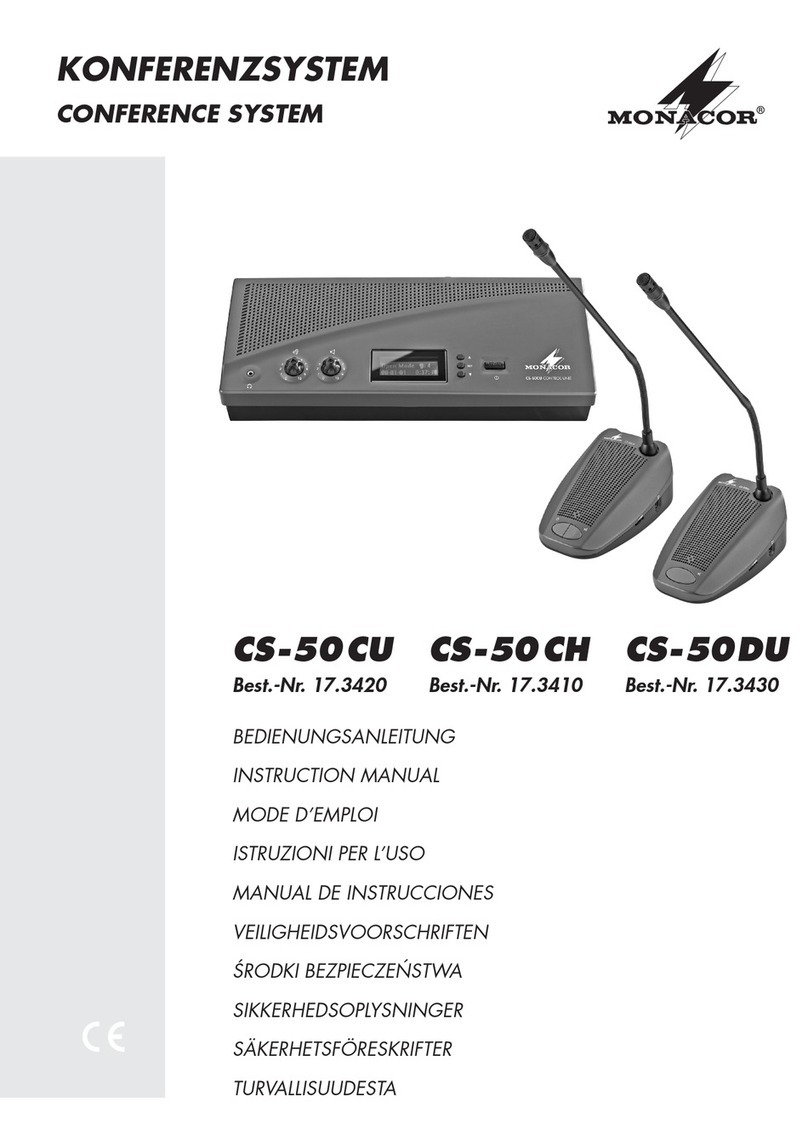
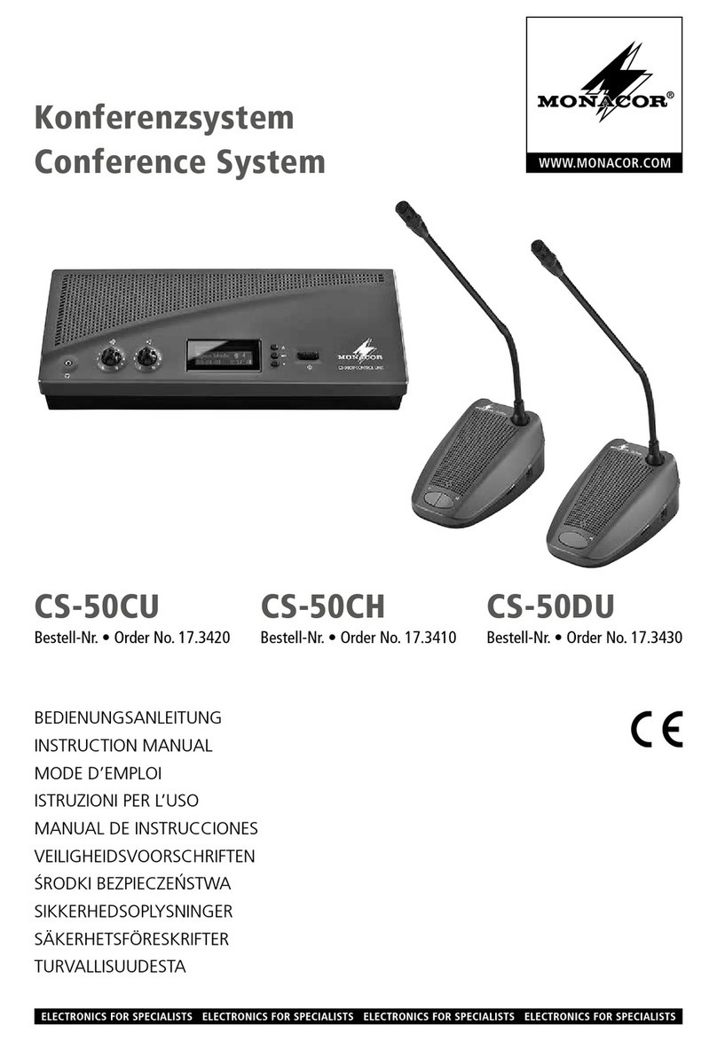
Monacor CS-100 Series User manual

1/14
Instruction Manual
CS-100 Series

2/14
Contents page
Overview ............................................................................................................. 3
Safety Instructions............................................................................................... 5
CS-100 Series..................................................................................................... 6
Front Panel Description....................................................................................... 6
Rear Panel Description........................................................................................ 7
Installation and Setting ........................................................................................ 8
1. General installation.......................................................................................................8
2. Quick Start.....................................................................................................................9
3. LED display and operation.........................................................................................10
3.1 Open Mic .............................................................................................................................10
3.2 Override ...............................................................................................................................10
3.3 Auto Off(Voice control)..................................................................................................10
3.4 Auto Save Settings...............................................................................................................10
Microphone Description......................................................................................11
Tabletop Chairman Unit –CS-100CU............................................................................. 11
Tabletop Delegate Unit –CS-100DU ..............................................................................12
CS-100 Main Control Unit Technical Specifications..................................................... 13
Microphone Unit Technical Specifications ...................................................................14

3/14
Overview
Thank you for purchasing CS-100 conference system from Monacor.
CS-100 is the easiest digital conference system with superb performance and elegant design
which can be used in various conference rooms.
CS-100 main control unit has the latest built-in digital module which can control up to 10
chairman units and 128 delegate units. What’s more, the built-in pre-mixer and amplifier can
definitely meet your requirements for any occasion.
The main control unit runs auto-detection to check if all the units work properly when turning on,
facilitating timely system detection.
High reliability is our utmost purpose when developing CS-100 conference system. Each main
control unit and its fittings have all gone through careful assembly and strict test in our ISO 9001
approved factory. The excellent performance, high reliability and reasonable price make it the
indispensable conference system for you.

4/14
System Features
Main Control Unit
1. Auto-detect connection
2. Digital control capability: 10 chairman units and 128 delegate units
3. Several LED indicators and conference mode setting buttons
4. Built-in pre-mixer
5. Built-in amplifier
Chairman Unit
1. Types: Tabletop and flush-mounted
2. Microphone on/off button, control button
3. Pliable in anywhere within circuit
4. A maximum of 10 units can be installed
5. ID code setting: 7-bit DIP switch
Delegate Unit
1. Types: Tabletop, flush-mounted and hand-held
2. Microphone on/off button
3. A maximum of 128 units can be installed
4. ID code setting: 7-bit DIP switch

5/14
Safety Instructions
1. Please read and observe these instructions before installing and using the apparatus.
2. Use only accessories specified by the manufacturer. The manufacturer is not liable for damage
caused by the use of non-specified accessories.
3. Install the apparatus and its accessories carefully. Strike and fierce shaking may damage the
apparatus.
4. Make sure the power cord is fixed properly.
5. Do not overload wall outlets and extension cords as this can result in a risk of fire or short circuit.
6. To reduce the risk of damage from lightning strikes, it is important that all electric cables should
be bonded to the same grounding point.
7. Do not block any ventilation openings to prevent overheating and malfunction.
8. Do not expose the apparatus to rain or moisture.
Humidity may lead inside components to damage. Appropriate shelter is necessary when
placing it outside (Best working environment: Temperature 0°C ~ 40°C <32°F ~ 104°F>,
humidity below 90%).
9. Please do not switch on and off the apparatus rapidly.
Rapid switch on and off the apparatus should be avoided all the time to prevent inside sensitive
electronic circuits from being damaged by surges.
10.Do not clean the apparatus and its accessories with chemical solvents. Use only a clean,
dry/dampish cloth.
11.Refer to maintenance technician when the apparatus has been damaged in any way, such as:
A• power-supply cord or plug is damaged
B• liquid has been spilled in
C• has been exposed to rain or moisture
D• has been dropped
E• objects have fallen into the apparatus
F•does not operate normally
12.Note: When the printed circuit board is going through electric static treatment, correct ESD
safety precaution and grounding should be assured.
13.Note: Before connecting the apparatus to main AC, please select the supply voltage in
accordance with the wall voltage in your country to prevent damage. Refer to Installation and
Setting (Page 8) for selecting.
14.Warning: Do not disassemble or remodel the product, as these actions may lead to electrical
shock or damage. The guarantee on the product will become null if the product is ever
disassembled.

6/14
CS-100 Series
Front Panel Description
Master
-8 -5 0
-2 +2
Bass
Conference TrebleAux 1Mic 3Mic 2Mic 1 Aux 2
Open Mic Override Auto Off
1 2 43 7 865 9 30 45 0
EDC Serice Conference System Control
21 4 56
78
3
1. Mic 1~3 Volume Control
2. Aux 1 Volume Control –for external input sound and Chairman Mode beep
Aux 2 Volume Control –for external input sound
3. Conference Volume Control –for conference microphone output
4. Treble Control and Bass Control
5. Master Volume Control –for entire system
6. Power Switch
7. Output Level Indicator LED
8. Control Mode Indicator LED
Open Mic –Open microphone number setting (from 1 to 9 microphones)
All LEDs are on (1~9) shows the entire system is opened (unrestricted)
All LEDs are off shows Chairman Mode. All delegate microphones cannot talk
Override –press for Override Mode
Auto Off –microphone auto-cutoff duration
30/45: If there’s no sound input for 30 or 45 seconds, delegate microphones will
be turned off automatically.
0: Deactivate this function.

7/14
Rear Panel Description
6789101113
15 16 5 4 3 2 1
MIC 1
220V
LINK 3 LINK 2 LINK 1
MIC 3 MIC 2
L.SPEAKER
110
STAND BY
SPEED DOME
RS-232
110
MIC 4
1AUX 410
MIC 4
AUX OUT VARIABLE 1 Conference
AUX INPUT
24
EQUALIZER
OUT IN
FUSE 250V 8A
SPEAKER 8£[
+- - +
~ AC FUSE 250V T8A
~ AC 110V/220V
50/60HZ
CAUTION:
.TO PREVENT ELECTRIC SHOCK
DO NOT REMOVE COVER(OR BACK)
.NO USER SERVICEABLE PARTS
TO QUALIFIED SERVICE PERSONNEL
RISK OF ELECTRIC SHOCK
DO NOT OPEN
CAUTION
!
MADE IN TAIWAN
CONTROL UNIT
http://www.bxb.com.tw
1214
1. Link 1~3 –Conference unit connectors
2. L.Speaker Volume Control –for conference unit internal loudspeaker
3. Standby Conference Unit Connector (Invalid)
4. Speed Dome RS-485 Ports(RJ-11)(Invalid)
5. RS-232 Port (Invalid)
2nd foot: Transmitted Data (Tx)
3rd foot: Received Data (Rx)
5th foot: Signal Ground(G)
6. Conference Unit Internal Loudspeaker Input
7. Mic 1~3 –dynamic microphone input(6.3Ø)
8. Mic 4 –dynamic microphone input(6.3Ø)and volume control knob
9. Aux 4 Volume Control –for external input sound
10. Aux Input Terminals
11. Conference microphone sound output and external sound processor terminals
Aux out –sound output, volume is not controlled by Master Volume Control
Variable –sound output, volume is controlled by Master Volume Control
Equalizer –external sound processor terminals, connect to timbre facilities such as external
equalizer and dynamic expander. The factory set in/out a short circuit direct output.
12. Earth Ground Connection Screw
13. SPEAKER 8Ω –internal 40W×2 amplifier and low resistance 8Ω speaker signal output terminal
14. Supply Voltage (AC 110V/220V, 50/60HZ) Selector Switch
15. IEC Socket –Used for A/C Line Interconnect with AC fuse(standby fuse:AC 8A)
16. DC fuse(DC 8A)

8/14
AC 110V/60Hz
AC 220V/50Hz
Installation and Setting
1. General installation
1.1 Select supply voltage
110V
~ AC FUSE 250V T8A
~ AC 110V/220V
50/60HZ
CAUTION:
.
.
220V
~ AC FUSE 250V T8A
~ AC 110V/220V
50/60HZ
CAUTION:
.
.
The supply transformer has been designed for use either 110V or 220V, 50/60Hz, selected by a
slide switch on the rear panel. Please make sure you select the correct supply voltage before
turning on the apparatus; otherwise it may cause serious damage.
1.2 Connections between main control unit and chairman/delegate units
TOP TOP
TOPTOP
TOP
http://www.bxb.com.tw
CONTROL UNIT
MADE IN TAIWAN
!
CAUTION
RISK OF ELECTRIC SHOCK
DO NOT OPEN
CAUTION:
.TOPREV ENT ELECTRIC SHOCK
DO NOT RE MOVE COVER(OR BACK)
.NOUSER SE RVICEABLE PARTS
TO QUALIFIED SERVI CE PERSONNEL
~ AC 110V/220V
50/60HZ
~ AC FUSE 250V T8A
EXPAND
POWER
AC CONTROL
+
--
+
SPEAKER 8Ω
FUSE 250V 8A
IN
OUT
EQUALIZER 42 AUX INPUT
3
1VARIABLE
AUX OUT
MIC 4
10
AUX 4
1MIC 4101
RS-232 SPEED DOME STAND BY
101
L.SPEAKER
MIC 2MIC 3
LINK 1LINK 2
LINK 3
220V
BXB
1.2.1 There are three links on the rear panel; they can be connected in random orders.
1.2.2 Chairman/delegate unit is equipped with a hidden connecting terminal. When connecting, you can
hide wiring with Y-shaped cable and neaten the conference room.
1.2.3 Chairman unit can be placed anywhere in the circuit.
1.2.4 When disconnecting any conference unit, please turn off the apparatus first.

9/14
2. Quick Start
2.1 After making sure all the above steps are done, plug in AC power supply and turn on power switch.
The LED on front panel will show the previous conference setting.
2.2 When turning on the conference system, it will start auto-scanning if all the units work properly. The
light ring on normal microphone will turn on. Conversely, flashing light ring shows false connection.
2.3 To check the connection, turn off the apparatus before disconnecting any units. Turn on the power
switch again when finish checking.
2.4 Press any button on chairman/delegate unit to cancel light ring or wait for 30 seconds (it will auto-off)
and start the conference.
Open Mic Override Auto Off
1 2 4
3786
5930 45 0
Conference System Control

10/14
3. LED display and operation
3.1 Open Mic
3.1.1 1~9:Press “Open Mic” button to open 1~9 delegate microphones.
3.1.2 Open system:When 1~9 LED all light up shows the whole system is opened. All the delegate
microphones can talk.
3.1.3 Chairman mode:1~9 LED are all off. Only chairman microphone can talk.
3.2 Override
3.2.1 Override mode:One overrides another. For instance, if you open one microphone, it means only
one delegate microphone can talk at a time. When one is talking, while the second conference
microphone is turned on, the previous talking microphone will be switched off automatically. If you
open three microphones, it means starting the fourth microphone will disable the first one.
Starting of the fifth will disable the second. Chairman microphone is not restricted in any modes.
3.3 Auto Off(Voice control)
3.3.1 Voice control:When delegate microphone receives no sound signal in 30/45 seconds,
microphone will auto-cutoff. Chairman microphone is not applied.
3.3.2 Select time
30:Delegate microphone will auto-cutoff if it receives no sound signal in 30 seconds.
45:Delegate microphone will auto-cutoff if it receives no sound signal in 45 seconds.
0:Deactivate the function.
3.4 Auto Save Settings
3.4.1 The main control unit saves above settings automatically. Even turning off the apparatus or
confronting power cut wouldn’t erase its memory.
Open Mic Override Auto Off
1 2 4
3786
5930 45 0
Conference System Control
○,1

11/14
Microphone Description
Tabletop Chairman Unit –CS-100CU
Operation:
1. Press “Talk” button to turn on microphone. Both the button and the light ring on microphone
will light up.
2. When turn on the microphone, build-in speaker on the unit will be silent to prevent echo.
3. Press “Control” button to turn off all delegate microphones. Delegate can press “Talk” button
again to continue talking.
4. DIN type microphone and the base can be separated. It is not only easy to install and
maintain for fixed areas, but also easy to transport and store for mobile areas.
5. Single Y-shaped connection cable and the built-in socket make the conference area tidy and
neat.
○,1 Talk button(with backlight indication)
○,2 Chairman Control Button(with backlight
indication)
○,3 Build-in speaker for decentralized sound
○,4 Built-in socket for DIN type microphone
○,5 Recorder output plug
○,6 Built-in socket for connection cable

12/14
Tabletop Delegate Unit –CS-100DU
Operation:
1. Press “Talk” button to turn on microphone. Both the button and the light ring on microphone
will light up.
2. When turn on the microphone, build-in speaker on the unit will be silent to prevent echo.
3. DIN type microphone and the base can be separated. It is not only easy to install and
maintain in fixed areas, but also easy to transport and store in mobile areas.
4. Single Y-shaped connection cable and the built-in socket make the conference area tidy and
neat.
○,1 Talk button(with backlight indication)
○,2 Build-in speaker for decentralized
sound
○,3 Built-in socket for DIN type
microphone
○,4 Recorder output plug
○,5 Built-in socket for connection cable

13/14
CS-100 Main Control Unit Technical Specifications
TECHNICAL DATA
◎Frequency response:100HZ~16KHZ
◎LINE IN:-4dB~+6dB≧10KΩ(balanced)
◎LINE OUT:-4dB~+12dB≧200Ω(balanced)
◎Sensitivity:-60dB
◎Total Harmonic distortion:≦0.5%
◎S/N:90dB
◎Conference microphone connection:D type express port x 3 sets
◎Mixer
Mic input:4 sets 600Ω/6mV/-22dB
Line input:4 sets 20KΩ/300mV/-10dB
◎Power amplifier:40W(8Ω)×2
◎5 LED level display
◎Power:AC110/220,50/60Hz,Power LED light
PHYSICAL DATA
◎Dimension and weight
Height:100(mm)
Wide:430(mm)
Depth:230(mm)
Weight:10(KG)
Accessory:19" brackets are included
Surface:Black, against rusty paint

14/14
Microphone Unit Technical Specifications
◎Type: Heart type capacitance
◎Frequency response: 100 Hz~ 16 KHz
◎Sensitivity: -23 dBv/PaMax.
◎Sound Voltage: 126 dB (3% THD)
◎S/N ratio: >20 dB (1 kHz)
◎Dimensions: 66 mm (2.5inch)
◎Frequency response: 120 Hz - 16 kHz
◎Rated input: 0.5W RMS
◎Voltage: DC12~18V
◎Connections: DIN8 -DIN8(Y Type)
◎Earphone/REC plug:3.5Ø,stereo
Appearance:
◎Base dimensions: 140 x 48 x 150mm (W x H x D)
◎Mounting: Table-top
◎Microphone length: 48 cm (length)
◎Net Weight: 0.82kg (Including Mic)
This manual suits for next models
2
Table of contents
Other Monacor Conference System manuals
Popular Conference System manuals by other brands

TANDBERG
TANDBERG Maestro MXP user manual

Emblaze-VCON
Emblaze-VCON xPointS user guide

Konftel
Konftel Konftel 300IP user guide

Grandstream Networks
Grandstream Networks IPVT10 Administration guide

Grandstream Networks
Grandstream Networks UCM63 Series Configuration guide

Veris Industries
Veris Industries H8163-CB installation guide