SMARTdesks VISTA Installation guide

VISTA Video Collaboration Table™
Typical
ASSEMBLY INSTRUCTION MANUAL
Assembly requires two people working together.
Video monitor and mounting bracket are not included and separately
purchased. Refer to your manufacturer’s video monitor mounting
bracket instructions for wall mounting to VISTA’s freestanding wall.
www.smartdesks.com
800 770 7042
©2013 CBT Supply, Inc. dba SMARTdesks® All rights reserved.
SMARTdesks® is a registered trademark of CBT Supply, Inc.
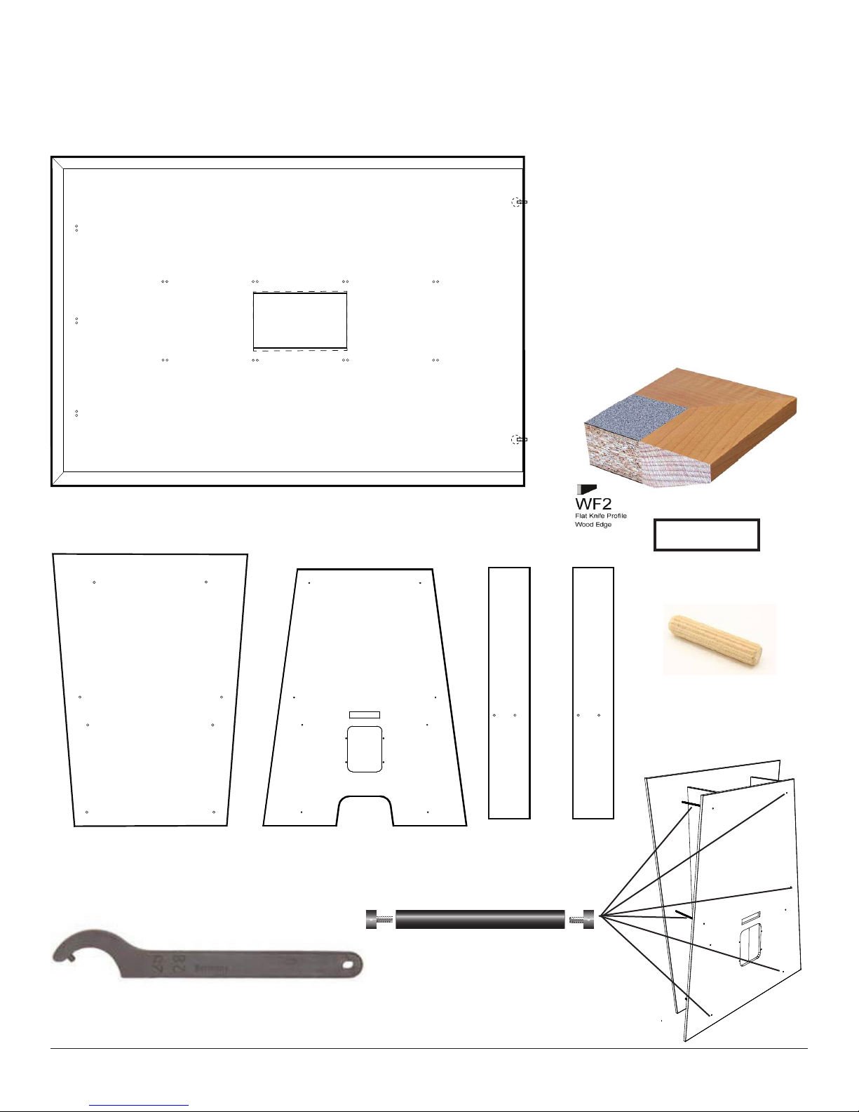
PARTS IDENTIFICATION
One top banded on 3 sides
• Dimensions 72 x 50
• Top finish #7285-58 Violin Figured
Annigre
• Wood edge maple hardwood
stained to match
#7012-58 Amber Maple
• WF2 Edge Profile
Please note that the VISTA Video Collaboration Tables for this installation
are NOT THE SAME. Each has been customized for its installation space. Be
sure that your parts are for the same MARK NUMBER.
Trapezoidal Back Wall
56w x 78h
Uprights (2 each)
11.5 w x 74h
Trapezoidal Front Wall
58.75w x 74h
Shelf (1 each)
9 deep
Stand-Off Bars (6 each)
11.5” long x 1”diameter with threaded
inserts, plus 2 each tapped end caps.
Black Aluminum.
Fixed Pin Spanner Wrench
Used for tightening the Stand Off Bar End Caps
800 770 7042 SMARTdesks Technical Assistance 2 www.smartdesks.com
26 wood Dowels
12 per each vertical x 2
= 24 and two for each
equipment shelf = 26

800 770 7042 SMARTdesks Technical Assistance 3 www.smartdesks.com
Table End Base
Panel(1 each)
Keel Side Panels
2 total quantity
Keel Bottom (2 for each table top)
4 total quantity
Thispartfastenstosidepanelsandkeel
Thispartfastenstoundersideoftop
Thispartfastenstosidepanelsandkeel
Thispartfastenstoundersideoftop
Maxifix Cam
262.87.003
Maxifix End Pin
262.87.781
Surface Connector Female
262.70.431
This part fastens to side panels
and keel.
Surface Connector Male
262.70.413
This part fastens to underside
of top.
Surface connectors cannot be removed from their mounting holes. The females
will ship installed and the males will need to be inserted. This is done to reduce
confusion in assembly.
Surface Connectors : 9 per top, 3 each side of Keel (6); (3) on End panel.
Minifix Cam
262.26.623
Minifix End Pin
262.27.163
Access Panel
2 total quantity
Keel Stretchers
4 total quantity
Mini Fix Pins 24 total = 8 for wall
panels (4) and equipment shelf
ends (4); 8 for Keel Bottoms; 8 for
stretchers in Keel.
Keku Clips
Male
Female
Maxi Fix End Bolt Pins 2 to go through
wall into wall end top
MaxiFix Cams 2 for tops

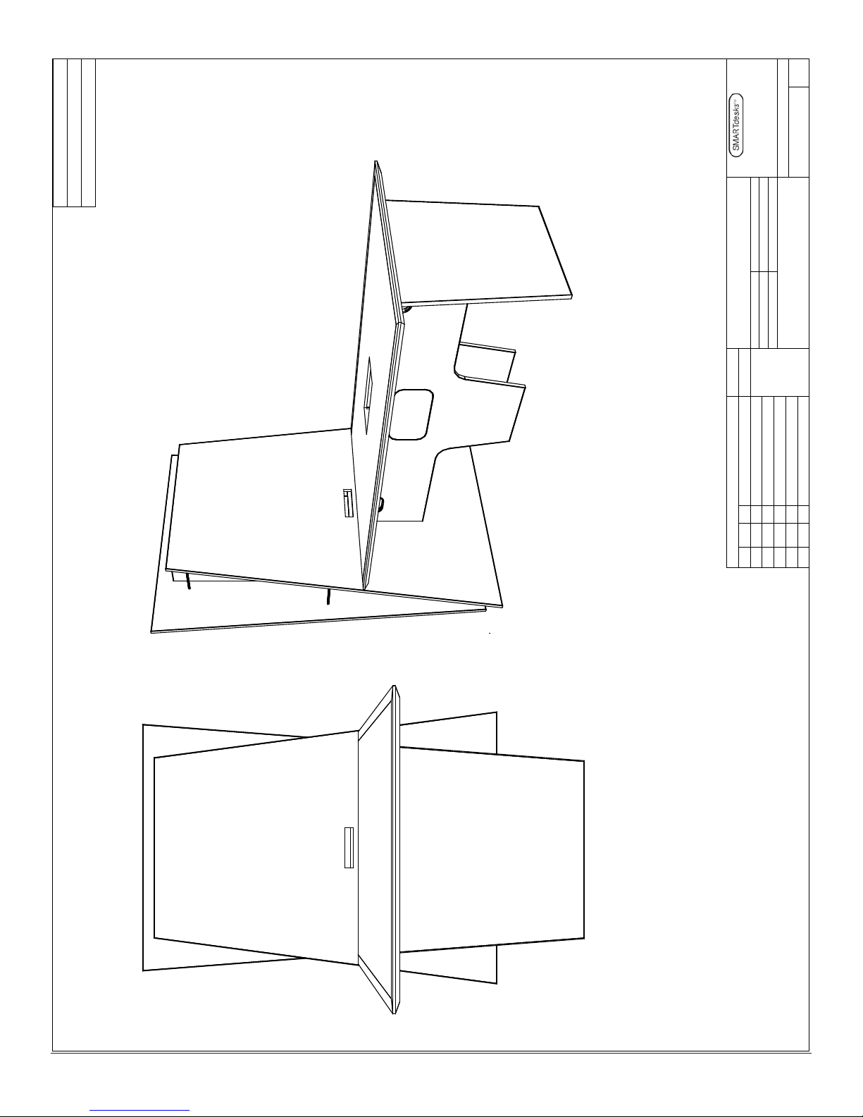
Approach to Assembly
VISTA must be assembled in this order
to facilitate the installation of equip-
ment. Coordinate with your IT specialists
so technology can be installed at the
proper stage. Assembly should be done
as close as possible to the final installa-
tion position to avoid putting stress on
the components.
1. The Keel Base Assembly is made
first, consisting of two Keel Side
Panels, one Table End Panel, and the
Keel Bottoms.
2. The Front Wall is tied into the Keel
Base Assembly so that it is free-
standing.
3. Uprights and Shelf are applied
4. IT Specialists install components
and video monitor mount (not in-
cluded). The video monitor mount
has its own installation instructions
for mounting to a wall. The VISTA
front wall should be structurally
sound for the load if robust bolts,
washers and nuts are used for
through bolt fastening. Installation
with wood screws is not recom-
mended.
5. With VISTA in final position, install
the Table Top to the base and wall.
6. The very last thing to be installed is
the back wall. When installed there
is limited access to technology on
the shelf and the monitor mount.
To make changes to the technology
installation, the back wall should be
removed for service
7. If the VISTA needs to be moved to a
different location, disassemble and
reassemble in the desired location.
Front Wall
Back Wall
Monitor and Mount
attach here
Uprights
and Shelf
800 770 7042 SMARTdesks Technical Assistance 4 www.smartdesks.com
Table Top edged 3 sides
Keel Base Assembly
End Base Panel
Orientation for assembled VISTA MARK 16 C

Step 1
Make the Keel Base Assembly
Start by affixing the Keel Base Panels and Keel Stretcher
Panels to one side of the Keel. Use Minifix Pins and Cams.
Install the second Keel Base with pins and cams.
Install the Table End Panel with pins and cams.
How Pins and Cams work
The arrow of the cam points in the direction of the insertion
channel. The pin is inserted, and the cam is tightened with a
Phillips No. 2 screwdriver.
Keel Base Panels
Table End Panel
Keel Bottoms
Keel Stretchers
Access Panel (pre-installed)
MATERIAL:
FINISH:
EDGE:
REVISIONSTOLERANCES
SYMDATE BY
UNLESS SPECIFIED
OTHERWISE
DESCRIPTION
DATE:
SCALE:
CHK'D BY: CNC NO.
CAD NO.
DRWN BY:
PART
NAME
NOTICE: This drawing is the property of CBT Supply, Inc. dba SMARTdesks
and contains proprietary information that is not to be usedexcept in
the consideration of bids or proposals tendered herewith. Reproductions
or copying of the drawing, in whole or in part, is prohibited.
PRODUCT
GROUP
DRAWING NO.REV.
DECIMALS
.X :_____
.XX :_____
.XXX :_____
ANGLE :_____
514F Progress Drive
Linthicum, MD 21090
800.770.7042
www.Smartdesks.com
PO# 7292
MARK 16C TABLE
ROOM: 205A (1)
FINISH: TOP: #7285 58, "Violin Figured Annigre"
WOOD EDGE: #7012 58 "Amber Maple"
MATCH WF2 EDGE PROFILE
BASE PANEL: #7285 58, "Violin Figured Annigre"
KEEL: BLACK LAMINATE
50.000
30.000
72.000
ACCESS PANEL
T-EDGE CUTOUTS
Detail of Table.
Do not attach the top in step 1.
800 770 7042 SMARTdesks Technical Assistance 5 www.smartdesks.com

Step 2
Front Wall Assembly
To make a free-standing structure, tie the
front wall into the keel assembly with
Maxifix pins and cams. Do this in the final
position for the VISTA installation.
800 770 7042 SMARTdesks Technical Assistance 6 www.smartdesks.com
Maxifix Cam
262.87.003
Maxifix End Pin
262.87.781
Install the uprights and shelf
Use dowels to hold the uprights in place. Each upright uses 12 dowels.
Install the shelf to the uprights using 2 dowels to the front wall and 4
Minifix pins and cams.
Install the Standoffs to the front wall, screwing in the end caps with the
Fixed Pin Spanner Wrench.
Uprights
Dowels
Shelf
Stand-Offs
Stand-Offs
Stand-Offs
Dowels
Dowels
Fixed Pin Spanner
Wrench
Used for tightening the
Stand Off Bar End Caps
Upon completion, if you are
working on Mark 15, tie in the
second Keel Assembly using
pins and cams.
At this point, coordinate with
IT to let them install the tech-
nology, including the Video
Monitor Mount.
When it is time to mount CPU
holders, IT should notify that
the table tops can be applied.

50.000
30.000
60.000
30.000
ACCESS PANEL
T-EDGE CUTOUTS
Install the table top
Female surface connectors have
been pre installed in the Keel Side
Panels. Insert the Male Surface
Connectors into the holes drilled
on the bottom surface of the Table
Top.
Capture the Surface Connectors
and tighten the set screws.
Access Panel
1 per Keel Side Panel
Male Female
Keku Clips
The Access Panels ship pre-
installed using Keku Clips.
Tie in Table Top
to Front Wall with
pins and cams
HumansScale CPU Holders will install to the
top in line with the Keel Scallops made for
cables to pass through the keel. The tops
must be installed before installing the CPU
Holders.
800 770 7042 SMARTdesks Technical Assistance 7 www.smartdesks.com

Install the back wall as the final step.
The back wall is the access panel for the monitor mount and the
technology that is placed on the shelf. While cables can be fished
through the Keel when complete, it takes less effort to do this
with the back wall and tops removed.
The back is applied with dowels and secured with Stand-Off End
Caps using the Fixed Pin Spanner Wrench.
•
•
•
•
•
Fixed Pin Spanner
Wrench
Used for tightening the
Stand Off Bar End Caps
800 770 7042 SMARTdesks Technical Assistance 8 www.smartdesks.com
Front Wall
Back Wall
•

800 770 7042 SMARTdesks Technical Assistance 9 www.smartdesks.com
77
2X 35MM .612" DEEP
22X 8MM 10MM DEEP
ROOM: 205A (1)
FINISH: TOP: #7285 58, "Violin Figured Annigre"
WOOD EDGE: MAPLE HARDWOOD STAINED TO
MATCH #7012 58 "Amber Maple"
WF2 EDGE PROFILE
72
50
3/8" WIDE X .59" DEEP TYP.
BACKER SIDE
8 1/4
9BACKER
BACKER SIDE
BACKER SIDE
MARK 16C TOP
SYM
Copyright CBT Supply dba SMARTdesks
C
This drawing is the property of CBT Supply, Inc. dba SMARTdesks
and contains proprietary information that is not to be used except in
the consideration of bids or proposals tendered herewith. Reproductions or
or copying of this drawing, in whole or part, is prohibited.
REVISIONS
BYDATE DESCRIPTION
ANGLS
CHK'D BY:
PART
.X
.XX
.XXX
-
-
+
-
+
-
+
UNLESS SPECI-
FIED OTHERWISE
DECIMALS
+
NOTICE:
DATE:
SCALE:
NAME
TOLERANCES
CNC NO.
DRWN.BY:
CAD NO.
RE V.
www.Smartdesks.com
800.770.7042
Linthicum, MD 21090
514F Progress Drive
DRAWING NO.
PRODUCT
GROUP
TM
desksSMART
EDGE:
FINISH:
MATERIAL:
(NOT RELEASED FOR PRODUCTION)
REFERENCE ONLY

800 770 7042 SMARTdesks Technical Assistance 10 www.smartdesks.com
MATERIAL:
FINISH:
EDGE:
REVISIONSTOLERANCES
SYMDATEBY
UNLESS SPECIFIED
OTHERWISE
DESCRIPTION
DATE:
SCALE:
CHK'D BY:CNC NO.
CAD NO.
DRWN BY:
PART
NAME
NOTICE: This drawing is the property of CBT Supply, Inc. dba SMARTdesks
and contains proprietary information that is not to be usedexcept in
the consideration of bids or proposals tendered herewith. Reproductions
or copying of the drawing, in whole or in part, is prohibited.
PRODUCT
GROUP
DRAWING NO.REV.
DECIMALS
.X :_____
.XX :_____
.XXX :_____
ANGLE :_____
514F Progress Drive
Linthicum, MD 21090
800.770.7042
www.Smartdesks.com
PO# 7292
MARK 16C WALL
ROOM: 205A (1)
FINISH: Wall: #728558,"Violin Figured Annigre"
Back Wall: #701258, "Amber Maple" (matte)
T-EDGE CUTOUT
13.500
56.000
13.500
56.000
78.000
58.750
74.000
8.625

800 770 7042 SMARTdesks Technical Assistance 11 www.smartdesks.com
MATERIAL:
FINISH:
EDGE:
REVISIONSTOLERANCES
SYMDATEBY
UNLESS SPECIFIED
OTHERWISE
DESCRIPTION
DATE:
SCALE:
CHK'D BY:CNC NO.
CAD NO.
DRWN BY:
PART
NAME
NOTICE: This drawing is the property of CBT Supply, Inc. dba SMARTdesks
and contains proprietary information that is not to be usedexcept in
the consideration of bids or proposals tendered herewith. Reproductions
or copying of the drawing, in whole or in part, is prohibited.
PRODUCT
GROUP
DRAWING NO.REV.
DECIMALS
.X :_____
.XX :_____
.XXX :_____
ANGLE :_____
514F Progress Drive
Linthicum, MD 21090
800.770.7042
www.Smartdesks.com
PO# 7292
MARK 16C TABLE
ROOM: 205A (1)
FINISH: TOP: #7285 58, "Violin Figured Annigre"
WOOD EDGE: #7012 58 "Amber Maple"
MATCH WF2 EDGE PROFILE
BASE PANEL: #7285 58, "Violin Figured Annigre"
KEEL: BLACK LAMINATE
50.000
30.000
72.000
ACCESS PANEL
T-EDGE CUTOUTS
800 770 7042 SMARTdesks Technical Assistance 12 www.smartdesks.com
MATERIAL:
FINISH:
EDGE:
REVISIONSTOLERANCES
SYMDATEBY
UNLESS SPECIFIED
OTHERWISE
DESCRIPTION
DATE:
SCALE:
CHK'D BY:CNC NO.
CAD NO.
DRWN BY:
PART
NAME
NOTICE: This drawing is the property of CBT Supply, Inc. dba SMARTdesks
and contains proprietary information that is not to be usedexcept in
the consideration of bids or proposals tendered herewith. Reproductions
or copying of the drawing, in whole or in part, is prohibited.
PRODUCT
GROUP
DRAWING NO.REV.
DECIMALS
.X :_____
.XX :_____
.XXX :_____
ANGLE :_____
514F Progress Drive
Linthicum, MD 21090
800.770.7042
www.Smartdesks.com
PO# 7292
MARK 16C
Table of contents


