Monarch SLS-115 User manual

SLS-115/230
Smart Laser Sensor
MONARCH INSTRUMENT
Instruction Manual
15 Columbia Drive
Amherst, NH 03031-2334 USA
Phone: (603) 883-3390
Fax: (603) 886-3300
E-mail: [email protected]
Website: www.monarchinstrument.com
Printed in the U.S.A.
Copyrighted by Monarch Instrument 2004, all rights reserved
1071-4859-111
CE DECLARATION OF CONFORMITY
As Manufacturer:
Monarch Instrument
Division of Monarch International Inc.
15 Columbia Drive, Amherst NH 03031 USA
declares under Monarch’s sole responsibility that the product:
to which this declaration relates is in conformity with the following directives and
standards when installed and operated in accordance with the user manual:
References: Retlif Testing Laboratories, (Report No. R-4283)
Technical Construction File SLS-0604 of June 2004
SLS - Smart Laser Sensor
15th June 2004
Manufacturer (Amherst,NH) Alan Woolfson, VP Engineering (Authorized Signature)
Directives: EMC 89/336/EEC
Low Voltage 73/23/EEC
Standards: EMC: EN61326:1997
Electrical Safety: IEC61010-1:2001
Laser Safety: IEC60825-1:2001

SAFEGUARDS AND PRECAUTIONS
WARNING - This product emits a visible beam of laser
light. Avoid exposure to the laser radiation. The use of
optical viewing aids (binoculars, for example) may
increase the ocular hazard.
CAUTION - The laser beam should not be intentionally
aimed at people or animals.
CAUTION - Use of controls or adjustments or
performance of procedures other than those specified
herein may result in hazardous radiation exposure.
WARNING - Use only the “PR Universal” charger supplied
with the product.
Read and follow all instructions in this manual carefully,
and retain this manual for future reference.
Do not use this instrument in any manner inconsistent
with these operating instructions or under any
conditions that exceed the environmental specifications
stated.
This instrument is not user serviceable. For technical
assistance, contact the sales organization from which
you purchased the product.
12
Examples:
1234.56<cr>
123456.<cr>
_ _ _ _0.0<cr> ( _ = space character)
10.0 CHARGING
Slide the Power switch (8) to the Off/Charge position and plug in the
charger. The Power LED (4) will blink red while the unit is fast charging.
The Power LED will blink amber when slow (trickle) charging. It will be
solid amber when the batteries are fully charged.
Note: If the charger is plugged in when the Power switch is the on
position, the batteries will be trickle charged during operation.
CAUTION: Use only the supplied PR-Universal charger with the
sensor.
11.0 ACCESSORIES
T-5 Reflective Tape, 5 foot [1.5 m] roll, ½ inch [13 mm] wide
T-5WP Waterproof Reflective Tape (honeycomb pattern), 5
foot [1.5 m] roll, 1 inch [25 mm] wide
SLS-CA-BNC Cable assembly with BNC connector (SO)
SLS-CA-W Cable assembly with tinned leads
SLS-CA-P Cable assembly with 1/8 inch [3.5 mm] mono plug (SO)
SLS-CA-RS232 Cable assembly with DB9 connector for RS232
SLS Battery Pack Replacement rechargeable Ni-Cd batteries
PR Universal Recharger/Power Supply with assorted adapter plugs

TABLE OF CONTENTS
TABLE OF CONTENTS
Symbols on the unit and in this manual:
Warning Direct current
Laser Beam
Caution Alternating current
Read Manual
1.0 SMART LASER SENSOR SPECIFICATIONS ............. 1
2.0 OVERVIEW ................................................................. 4
3.0 INDICATORS AND SWITCHES .................................. 5
4.0 QUICK START GUIDE ................................................ 6
5.0 CONNECTION DETAIL ................................................ 7
6.0 OPERATION ............................................................... 9
6.1 Auto Mode ...................................................................... 9
6.2 Manual Mode ............................................................... 10
7.0 ADVANCED FEATURE (TARGET POLARITY) ........... 10
8.0 AIMING THE LASER ................................................. 11
9.0 RS232 ....................................................................... 11
10.0 CHARGING ............................................................... 12
11.0 OPTIONS / ACCESSORIES ...................................... 12
11
To change the setting, move the Polarity switch (5) to the left (positive
pulse) for a white target or to the right (negative pulse) for a black target.
Turn the Sensitivity Adjust knob (7) to Max. Press and hold the Learn/
Gain button (6) until the Auto/Gain LED (3) blinks.
8.0 AIMING THE LASER
The proper operation of the Laser Sensor is dependent upon the alignment
to and reflectivity of the target. In order to aim the beam it is necessary to
stand behind the sensor and view the target along the plane of the beam. Do
not stare directly into the laser beam or the reflected light. For targets
greater than 5 feet and up to 65 feet from the sensor, mount the laser on a
tripod using the ¼ - 20 bushing on the bottom of the unit and attach T-5
reflective tape to the target.
To aid in locating the laser dot over a large distance, hold a piece of white
cardboard or equivalent in front of the laser. Progressively move the white
surface closer to the desired target. Then adjust the aim of the laser as
necessary.
In areas of high ambient light (outdoors), performance can be enhanced at
long distances by slipping a piece of black tube with a minimum inner
diameter of 0.6 inches, over the nose piece to act as an extension nose piece.
This tube should not deflect the beam in any way.
9.0 RS232
Baud rate = 9600, 8 bits, 1 stop bit, no parity.
When the unit is turned on, it will send out: “SLS<lf><cr>Vx.x<lf><cr>
0.0<cr>”. Where <lf> is the linefeed character, <cr> is a carriage return
character, and x.x is the firmware version number.
The unit will send out the current RPM as a right justified 7-digit ASCII
number that will always include a decimal point followed by carriage return.
The update rate is a function of the speed of the target and will not exceed
twice per second.

1
1.0 SMART LASER SENSOR SPECIFICATIONS
Laser Specifications:
Classification: Class 3R (per IEC 60825-1 Ed 1.2 2001-8)
Complies with FDA performance standards for laser products except for
deviations pursuant to Laser Notice No. 50, dated July 26, 2001.
Maximum Laser Output: 3mW
Pulse Duration: Continuous
Laser Wavelength: 650 nm
Beam Divergence: < 0.5 mrad
Beam Diameter: 4 x 7 mm typical at 2 meters
Laser Diode Life: 8,000 hours MTBF (1 year warranty)
Operating Range: Up to 65 feet depending on target reflectivity:
1/2” reflective tape (T-5) @3600 RPM: up to 65 ft. (19.8 m) or up to
75° from target
White/Black contrast @3600 RPM: up to 3 ft. (91 cm) or up to 45°
from target
Black mark on dental drill: up to 4 in. (10 cm) at over
260,000 RPM
Figure 1 Laser Warnings
AVOID EXPOSURE
LASER RADIATION IS
EMITTED FROM THIS
APERTURE.
Laser is on when this
indicator is illuminated.
10
In many applications, this is all
that is needed. In cases where the
target is marginal, the user may
need to manually adjust the
sensitivity after trying the Auto
mode.
6.2 Manual Mode
Aim the laser at your target. Turn
the Sensitivity Adjust knob (7)
between Min and Max until the
On Target LED (1) starts blinking
or comes on solid. If you can’t get a good setting, change the gain.
Press and release the Learn/Gain button (6) to change the gain of the
input amplifier. Each time the button is pressed, the gain is changed.
The Auto/Gain LED (3) will blink to show what gain has been selected.
If the button is held down, the gain will increase automatically after
each LED ‘blink’ pattern. Refer to Table 2. The larger the gain, the
weaker the signal being picked-up. Using a large gain for a strong signal
is not recommended since the input will saturate.
7.0 ADVANCED FEATURE (TARGET POLARITY)
The input circuitry can be set to optimally work with two different target
types: a reflective (white, shiny) target on a mostly non-reflective (black,
dull) background or a non-reflective (black, dull) target or a mostly reflective
(white, shiny) background. These will be referred to as a white target or a
black target. When the unit is first turned on, the On Target LED (1) will
indicate which target type the sensor is set up for. While the Laser On
LED (2) is blinking, the On Target LED will be on for a white target or off
for a black target. The unit will still work when set up for the “wrong”
target type, but it won’t have as great a range. When set for a white target,
the unit triggers on the black to white transition. When set for a black
target, the unit triggers on the white to black transition.
Number of blinks Gain
1 Strong Signal X 1
2 X 2
3 X 4
4 X 5
5 X 8
6 X 10
7 X 16
8 Weak Signal - Move
Closer X 32
Table 2 Auto/Gain Blinks

2
Max RPM: 500,000 RPM
Min. Trigger Duration: 10 µsec
Indicators: LEDs for On Target, Laser On, Auto/Gain, Power/Charge
Modes: Normal (manual) or Auto, and charging
Normal mode – manual adjustment of sensitivity / gain
Auto mode – auto learn, automatic gain control
Sensitivity Adjust: Single Turn knob on top panel in Normal mode
Voltage Requirements:
Operational: Internal: rechargeable batteries
External: +9 V 1VA
Charging: External: +9 V 3VA
Batteries: Internal 4 “AA” rechargeable NiCd 700mAh
Run Time: Over 6 hours continuous operation from fully charged
batteries @ 70 °F (21 °C)
Charge Time: Typically less than 3 hours @ 70 °F (21 °C)
PR Universal Charger:
Input: 100-240 V , 50-60 Hz
Output: 9 V , Dry location use only
Check charger label for power information.
Pulse Output:
SO: Source Output - Square Wave 0 to 3.9V typical @ 15mA
(PNP to 4.2V, 4.7K ohms to common) (TTL Compatible)
OC: Open Collector - Switches to common, External pull up
resistor to user supplied power (max 24 V ) required
9
6.0 OPERATION
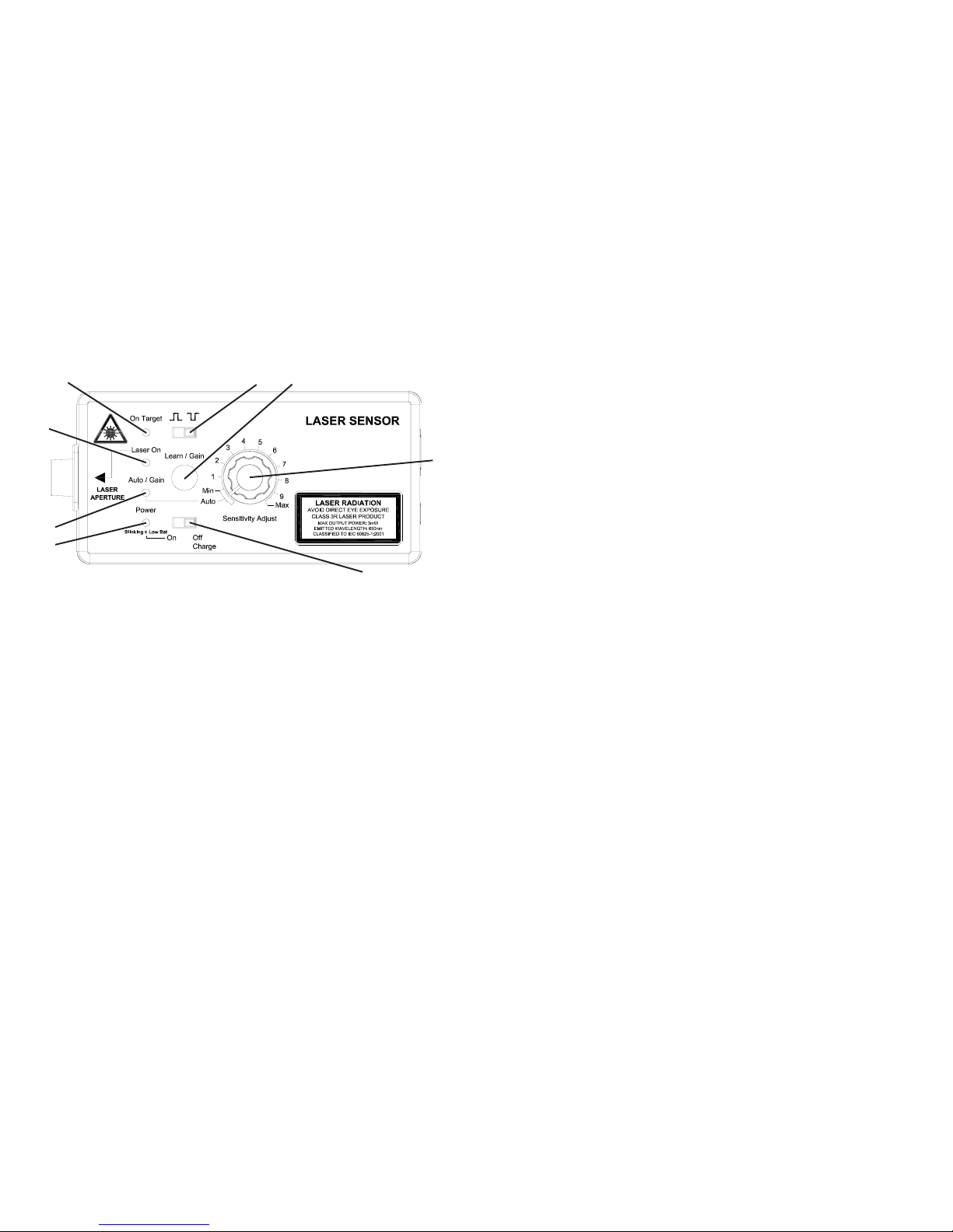
Note: Refer to Figure 3 for switch and button locations.
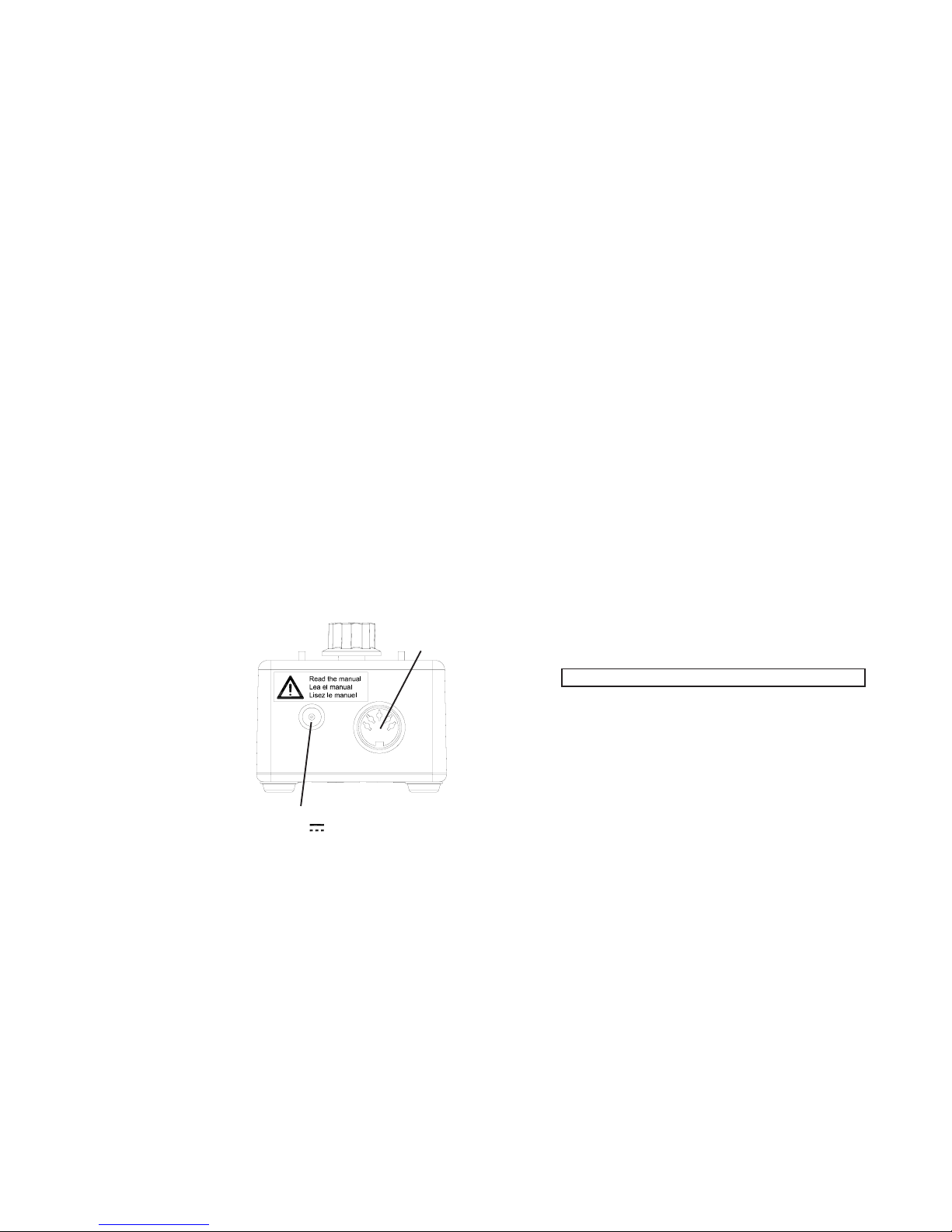
Turn the unit on by moving the Power switch (8) to the On position. The
unit may be operated from the internal batteries and/or the charger/power
supply. The internal batteries will be trickle charged when using the AC
charger/power supply. To turn the unit off, slide the Power switch (8) to
the Off/Charge position. If the charger is plugged in, the batteries will
charge.
The sensor emits a laser beam, which is reflected back by a target (reflective
tape/paint, keyway, contrasting colors, etc). This reflected light is sensed
and amplified then compared to a threshold level (sensitivity) - the lower
the threshold level, the more ‘sensitive’ the sensor is. Whenever the amplified
signal is above the threshold, the output goes high (positive pulse) or low
(negative pulse). The user can select either a positive or a negative output
pulse using the Polarity switch (5).
The gain of the input amplifier and the sensitivity can be adjusted manually
or automatically. This allows the unit to be used with many types of
targets at various distances and contrasting color conditions. To select the
Auto mode, turn the Sensitivity Adjust knob (7) fully counterclockwise,
otherwise you are in the Manual mode. Reflective tape and high contrast
color applications should be able to use the Auto mode.
6.1 Auto Mode
Make sure the Sensitivity Adjust knob (7) is fully counterclockwise
and the Auto/Gain LED (3) is on. Aim the laser at your target. Press
and hold the Learn/Gain button (6) until the On Target LED (1) blinks
regularly or is on solid (depending on the RPM of the target). Release
the Learn/Gain button. The Auto/Gain LED will blink to show what
gain has been selected. Refer to Table 2.
This manual suits for next models
1
Table of contents